European Atomic Energy Community -
EURATOM
FIAT S.p.A., Sezione Energia Nucleare -Torino
Societa ANSALDO S.p.A. -
Genova
COLLISION TESTS WITH SHIP MODELS
TOPICAL REPORT
LEGAL NOTICE
This document was prepared under the sponsorship of the Commission of the European Communities.
Neither the Commission of the European Communities, its contractors nor any person acting on their behalf :
make any warranty or representation, express or implied, with respect to the accuracy, completeness or usefulness of the information contained in this document, or that the use of any information, apparatus, method or process disclosed in this document may not infringe privately owned rights; or
assume any liability with respect to the use of, or for damages resulting from the use of any information, apparatus, method or process disclosed in this document.
This report is on sale at the addresses listed on cover page 4
at the price of F.Fr. 20.55 B.Fr. 185.- DM 13.55 It. Lire 2,310 FI. 13.45
When ordering, please quote the EUR number and the title which are indicated on the cover of each report.
Printed by Van Muysewinkel, Brussels
Luxembourg, November 1971
This document was reproduced on the basis of the best available copy.
•! I
11
t
•·
.
European Atomic Energy Community - EURATOM Fiat S.p.A. - Sezione Energia Nucleare - Turin
Societa Ansaldo S. p.A. - Genoa
with the participation of:
Comitato Nazionale per !'Energia Nucleare - CNEN, Rome
TOPICAL REPORT ON COLLISION TESTS
WITH SHIP MODELS
1971
Prepared for publication by the Centro per gli Studi di Tecnica Navale (CETENA), Genoa, for the Directorate-General for Industrial, Technological and Scientific Affairs
with models for the purpose of evaluating the effectiveness of various types of ship-side structures designed to protect the reactor space in the event of collision.
During the initial stage of this part of the programme it became clear that a number of technical problems relating to the carrying out of such tests had to be resolved before any conclusive information could be derived from them. A series of 14 collision tests were performed between May 1963 and July 1970; the conditions for each test were specified only after analysis of the results obtained with the previous one, only one particular parameter being changed at a time. A set of twe steel models on a scale of 1 : 15, consisting of a ship's bow-section and a section representing the collision protection structures in the side of the reactor compartment of a nuclear ship, were constructed for each experiment.
The report contains an account of the general criteria adopted for these experiments and the particular considerations underlying the parameter varia-tions. A detailed description of the results is given and a tentative correlation with the full-scale example elaborated.
KEYWORDS
NUCLEAR MERCHANT SHIPS REGULATIONS
MOCKUP TESTING COLLISIONS
MECHANICAL STRUCTURES DEFORMATION
SAFETY
CONTENTS
1. Introduction 1.1 General
1.2
Collision tests on models performed by other researchers prior to, or in the same period as, the Ansaldo tests.1.2.1
Collision tests performed in Japan at the Yokohama Shipyard and Engine Works1.2.2
Collision tests performed by the Istituto di Construzioni Navali (Shipbuilding Insti-tute) of Naples University1.2.3
Collision tests performed by the "Deutsche Werft" at Hamburg on behalf of the GKSS2. Special requirements for the construction of nuclear ships issued by Classification Societies
2.1.1
American Bureau of Shipping2.1.2
Bureau Veritas2.1.3
Det Norske Veritas2.1.4
Germanischer Lloyd2.1.5
Lloyd's Register of Shipping 2.1.6
Nippon Kaiji Kyokai2.1.7
Registro Italiano Navale3.
General criteria adopted for collision tests withship models carried out under the Euratom/Fiat/ Ansaldo contract
3.1
Purpose of the tests and experimental apparatus3.2
Similarity theory and symbols3.3
Material and connections of model elements -Their assembly3.3.1
Physical tests on the steel materials for the models3o3.2
Joining of model elements3.3.3
Workshop assembly of model elements3.3.4
Mounting of models on carriage4.
Description of tests performed4.1.1
Test No.1
4 o 1 • 2 Test No • 211 11 12 12 14 16 17
5.
6.
4.1.3 Tests No. 3 and 4 4.1.4 Test No. 5
4.1.5 Test No. 6 4.1.6 Test No. 7
4.1.7 Test No. 8 4.1.8 Test No. 9 4.1.9 Test No. 10 4.1.10 Test No. 11
4.1.11 Tests No. 12 and 13 4.1.12 Test No. 14
Some further considerations on the results of the collision tests
Tentative correlation of collision results 6.1 Actual collisions
6.2 Collision tests with ship models
6.3 Distribution of deformation work between the bow of the colliding ship and the side of the struck ship
7.
Considerations on the structural strength of the colliding bowSummary table of the data from collision tests between ship models (see inside back cover)
LIST OF FIGURES
Fig. 1.
Fig. 2.
Fig.
3.
Fig.
4.
Fig.
5.
Fig.
6.
Fig.
7.
Fig.
8.
Fig.
9.
Collision experimental apparatus in the Yokohama shipyard
Installation for collision tests between models -CNEN Study Centre at the University of Naples
Ship side model
T3
Collision test by GKSS and Deutsche Werft AG
Acceleration and speed diagrams No.
8
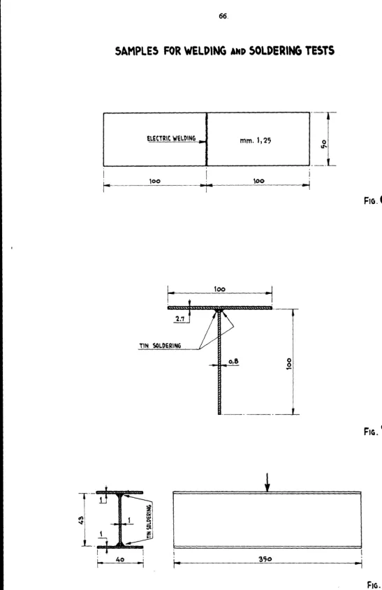
collision testSamples for welding and soldering tests
Samples for welding and soldering tests
Samples for welding and soldering tests
Samples for tin soldering tests
Fig. 10. Samples for tin soldering tests
Fig. 11. Elastic mounting for bow model
Fig. 12. Mounting of the ship side model Fig. 13. Elastic mounting for ship side model
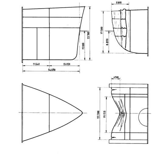
Fig. 14. Bow model for No. 1 collision test
Fig. 15. Ship cross section with collision barrier
Fig. 16. Ship side model for No. 1 collision test
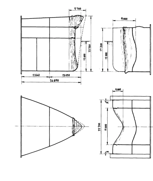
Fig. 17. Bow and ship side models after No. 1 collision test
Fig. 18. Bow model for No. 2 collision test
Fig. 19. Bow and ship side models after No. 2 collision test
Fig. 20. Ship side model for No. 3 collision test
Fig. 21. Bow and ship side models after No. 3 collision test
Fig. 22. Bow and ship side models after No. 4 collision test
Fig. 23. Bow and ship side models after No. 5 collision test
Fig. 26. Bow and ship side models after No. 7 collision test 83
Fig. 27. Bow and ship side models before No. 8 collision test 84
Fig. 28. Bow and ship side models after No. 8 collision test 85
Fig. 29. Bow and ship side models after No. 9 collision test 86
Fig.
30.
Bow and ship side models before No. 10 collision test 87 Fig. 31. Bow and ship side models after No. 10 collision test 88Fig. 32. Bow and ship side models before No. 11 collision test 89
Fig. 33. Bow and ship side models after No. 11 collision test 90 Fig. 34. Bow model for No. 12, 13 and 14 collision tests 91
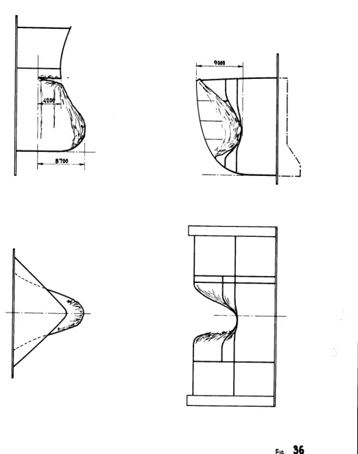
Fig. 35. Bow and ship side models before No. 12 collision test 92
Fig. 360 Bow and ship side models after No. 12 collision test 93
Fig. 37. Bow and ship side models after No. 13 collision test 94
Fig. 380 Bow and ship side models after No. 14 collision test 95 Fig. 39. Relation between volumes of material affected by the
collision and dissipated energy;
Total volume of material 96
Figo 4oo Relation between volumes of material affected by the collision and dissipated energy;
Volumes according to Minorsky procedure 97
Figo 41. Relation between volumes of material affected by the collision and dissipated energy;
Excluding plating and stiffeners normal to line of impact 98
Figo 420 Relation between volumes of material affected by the collision and dissipated energy;
100"fe volume of destroyed material, plus 65°fe volume of
deformed material 99
Fig. 43. Relation between volumes of material affected by the collision and dissipated energy;
Comparison of A
LIST OF PHOTOGRAPHS
1. 180° bending test of an electrically welded specimen 2. 180° bending test of a tin soldered T specimen
3.
Bending test of a tin soldered H specimen4o Bending test of a tin soldered cross shaped specimen
5.
Wooden moulding frame6.
Wooden moulding frame7.
Wooden moulding frame8.
Bending test of a slot tin soldered specimen9.
Bow model for collision test No. 110. Ship side model for collision test No. 1 11. Bow model after collision test No. 1
12. Ship side model after collision test No. 1 13. Bow model after collision test No. 2
14. Ship side model after collision test No. 2 15. Bow model after collision test No. 3
16. Ship side model after collision test No. 3
170 Bow model after collision test No. 4
18. Ship side model after collision test No. 4
19. Bow and ship side models after collision test No. 5
20. Bow model after collision test No. 6
21. Bow_ of the colliding ship after real collision 22. Ship side model after collision test No. 6
23. Side of the struck ship after real collision 24. Bow model after collision test No. 7
25. Ship side model after collision test No. 7
26. Bow model after collision test No.
8
27. Ship side model after collision test No.
8
28. Bow model after collision test No. 9
29. Ship side model after collision test No. 9 30. Ship side model after collision test No. 10 31. Bow model after collision test No. 10
32. Bow model after collision test No. 11
33.
Ship side model after collision test No. 11101 101 102 102 103 104 105 106 107 108 109 110 111
11 2 11 3 114
114
11 5
116
11 6
117
11 7
36.
Bow model after collision test No.13
12537.
Ship side model after collision test No.13
12538.
Bow model after collision test No.14
126SUPPLEMENTARY INFORMATION
Notice to Readers
A set of seven white prints of drawings on 1:10 scale, giving detailed information on the extent of the damage caused to the corresponding
models during collision tests No.
8-14
and indicating the plate-thicknesses and dimensions of their structural parts, can be obtained separately from the Commission's Centre for Information and Documentation. These are obtainable together with full-size copies of the complete acceleration and speed diagrams as recorded for each of the 14 tests described in the present report, in which a reduced scale example of such a diagram is given in Fig.5.
These. drawings and diagrams can be obtained from the CID at the address below at a price of B.Fr.500.- When ordering specify clearly:
"Supplementary information to topical report on collision tests with ship models - EUR 456oe11
•
Commission of the European Communities Centre for Information and Documentation
1. INTRODUCTION
1.1 General
The Euratom/Fiat/Ansaldo research contract concerning studies on a nuclear-powered ship and her reactor, in which the Comitato Nazionale per l'Energia Nucleare (CNEN) also participated, was signed in Brussels on 15 December 1961.
A tanker of about 53,450 tdw was selected by common agreement. After slight modifications during the design stage, this ship had the fol-lowing characteristics:
Length between perpendiculars Breadth
Depth to the main deck Draught (summer freeboard) Block coefficient
Full load displacement Displacement in ballast
230.00 m
31.00 m
17.30 m
12.00 m
0.785
69,200 tonnes 50,000 tonnes
A two-volume report was published in June 1965 on the intermediate
design of the tanker, the pressurized water reactor and the conventional-type main propulsion unit, which has a normal output of 23,600 metric hp and a maximum output of 29,000 metric hp. This report covered all the studies performed between January 1961 and June 1965.
In June 1968 a supplementary report was published coimrning the studies carried out by Fiat and Ansaldo between July 1965 and the end of 1967.
an ice-strengthened bow with a waterline entrance angle of
38°.
These collision tests, which were described in the above-mentioned supplementary report and are referred to again in this report, were numbered from 1 to
5
and from7
to9.
Collision test No. 6 was carried out with the purpose of reproducing on models an actual collision between a striking ship displacing 11,000 tonnes and a struck tanker in ballast (8,500 tonnes displacement).
This also will be returned to again later, it merely being noted here that the two models for test No. 6 were reduced to one-tenth of the ships' actual sizes, while all the models for the other collision tests were on a 1/15 scale.
The idea of using a striking bow of a type similar to that of the struck ship was abandoned when tests No. 10, 12, 13 and 14 were planned. In these tests two other types of bow were employed which were considered to be more dangerous in the event of collision, namely, the bow of a transatlantic liner with a waterline entrance angle of about 20° and the bow of a large ·tanker, with a large bulb and an entrance angle of about
86°
at the full-load waterline.The results of all the collision tests carried out by Ansaldo were described in the report published in 1971 on the studies performed by Fiat and Ansaldo hitherto.
1.2 Collision tests on models performed by other researchers prior to or in the same period as, the Ansaldo tests.
1.2.1 Collision tests performed in Japan at the Yokohama Shipyard and Engine Works (see "Research on the collision-resisting construc-tion of ship sides" by K. Kagami, T. Hamada et al., Symposium on Nuclear Ship Propulsion, Taormina, Italy, November 1960).
str~ctures of
45,000 tdw
tanker, both ships being assumed to be fully laden.Eight shipside models were tested, each having differently designed hull structures between the outer shell and the inner longitudinal bulkhead bounding the reactor space. The model of the striking bow was always of the same type.
The experimental apparatus consisted of a high tower from which the striking bow was suspended by means of swinging arms. The shipside model to be struck was fixed to a rigid mounting and the bow model struck it at the end of its run (see Fig. 1). The angle of impact between the col-liding bow and the struck ship side was always 90°.
The speed of the striking ship at the moment of impact was about 5 knots, since it was considered that most collisions occur near the coast or in port, and furthermore the speed of the striking ship is presumably re-duced as a result of action taken as soon as an accident is seen to be likely.
This opinion seems to be rather optimistic, but the tests carried out are
very interesting and the results can be extremely useful for comparative purposes.
The tests showed that better results (smallest penetration into the ship-side and largest bow deformation) were obtained when the outer side
plating was thicker (32 instead of 21 mm i.e., Rule thickness for the ship's actual size) and strong side girders were fitted. It was considerec that the outer shell plating acted as a membrane. The poorest result was recorded on a model having an outer side plating 21 mm thick (Rule thick-ness) and several light side girders.
As could be easily anticipated, the heaviest damage to the inner longi-tudinal bulkhead demarcating the reactor space occurred when the ship-side structures were fairly rigidly connected to the above bulkhead.
was the "explosion theory", according to which, if
,J.
= 20 is the model scale, the weight of the striking model is assumed to be equal to~
of the actual ship weight and its speed to be equal to the actual speed of the ship(5
knots= 2.57 m/sec, arbitrarily reduced to 2.15 m/sec in order to account for the fact that the struck ship has not really a rigid structure but an elastic one and can move sidewards when struck,thus entraining a mass of water which it is almost impossible to estimate).
1.2.2 Collision tests performed by the Istituto di Construzioni Navali (Shipbuilding Institute) of Naples University
See the papers by Prof. Franco Spinelli "Defense des reacteurs nucleaires de navire· contre lea abordages" (Protection of marine nuclear reactors against collision) published in the "Bulletin de l'Association Technique
Maritime et Aeronautique, No. 62, Year 1962 Session" and "Protection du compartiment du reacteur nucleaire contre les abordages. Resultats d'esaai
sur modeles" (Protection of nuclear reactor compartment against collision - Results of model tests) published in the "Bulletin, No. 64, Year 1964 Session".
These tests were carried out by means of an ,experimental apparatus which
was different from the one employed in Japan for the experiments
previous-ly described.
As can be seen in Fig. 2, the ship side to be struck was mounted on a frame on a carriage which was free to move after the impact and was fitted with three drift fins immersed in water tanks on both sides.
By means of such a system the lateral motion of the ship side model when
struck entrains a mass of water (which is a variable quantity according to the level of water in the tanks), as occurs in t~e event of an actual collision at sea.
The fins must have an area corresponding to the drift area of the struck ship reduced to the model scale.
height. The weight of the bow model, suitably ballasted, has to
be varied
according to the displacement adopted for the colliding ship.
All five sets of models described in Prof. Spinelli's paper published in
1964 were built to 1/15 scale.
Both the struck ship side and the bow of the colliding ship were con-sidered as belonging to a fully loaded 45,000 tdw tanker (60,750 tons displacement). The waterline entrance angle was 65°.
The structural elements were joined together by means of a 60% tin and 40% lead solder, which tests to determine tensile stress indicated to be a suitable choice.
Several speeds, ranging from 2.42 to 5.80 m/sec (4.7 and 11.275 knots), were adopted for the striking ship.
To permit valid comparisons, the type of ship side structure chosen was the same as that tested in Japan (T
3
model, see Fig.3).
In the fifth test the structure was changed by placing the longitudinal bulkhead demarcating the reactor space at a shorter distance from the outer plating (about
6
m instead of 7.50 m).The similarity law followed was the explosion theory, as for the tests carried out in Japan. According to this theory the ship's speed is the same as the model speed.
In each test the following data were recorded:
- values of speed and acceleration, for both the striking and the struck models,
- stresses recorded by means of strain gauges.
This percentage, which was less than: 100,.6 in the lower speed range, was estimated to be about 50% for the highest speed used.
Results obtained from collisions of models of the same type at the same speed in the tests carried out both in Japan and in Naples are very similar and fully comparable, notwithstanding the different systems employed to perform them.
Even at the highest speed (more than 11 knots), the damage caused to the lower part of the ship side model did not affect the inner longitudinal bulkhead.
1.2.3 Collision tests performed by the "Deutsche Werft" at Hamburg on behalf of the GKSS (Gesellschaft fUr Kernenergieverwertung in Schiffbau und Schiffahrt, Hamburg). (See article "Kollisionsversuche mit Schiffsteilmodellen" by G. Woisin, published in "Kerntechnik, Iso-topentechnik und Chemie", No. 8,
1967).
Tests were carried out with models on a scale of
1/7.5,
This scale was adopted in order to make electric welding easier owing to the larger dimensions of the models.The model of the ship side, as can be seen in a figure printed in the above article, reproduced the side structure of the German nuclear ship "Otto Hahn", while the bow was considered as being that of a transatlan-tic liner (Bremen). The displacement of the striking ship was estimated at 30,000 tonnes and the displacement of the struck ship 25,000 tonnes. The speed of the striking model was 5.95 m/sec
(11.6
knots).The experimental apparatus employed for performing these tes~s was of the same type as that built by the University of Naples (see Fig. 2). The ship side model was fixed to a rigid mounting.
Fig. 4 taken from the above-mentioned article, shows the models after the collision. In the diagram the structures of the models are shown schematically.
previously been carried out on separate structural elements of the col-lision protection.
Some similar collision tests have been performed, but their results have not been officially reported.
As is stated in Section 4.1.9 below, a bow model identical to that used in the above test performed by Deutsche Werft was built for test No. 10 carried out by Ansaldo, making use of the experimental apparatus avail-able at Naples University.
2. SPECIAL RE~UIREMENI'S FOR THE CONSTRUCTION OF NUCLEAR SHIPS ISSUED BY CLASSIFICATION SOCIETIES
Before describing the 1~ collision tests performed under the Euratom/ Fiat/Ansaldo contract and before deducing proper technical considerations from these tests, it was felt desirable to outline here the requirements published by various Classification Societies as a guidanc~ to the design of nuclear-powered ships in order to attain safety when a collision occurs in way of the reactor compartment.
2.1.1 American Bureau of Shipping
First of all it has to be established that the collision protection is so effective that the longitudinal bulkhead bounding the reactor space
is not damaged as a result of the collision.
To ensure this, the protection is to be longitudinally extended so that it can also be efficient if the colliding ship has an angle of impact of between 30 and 150° with the struck ship. The protection must extend vertically so as to preclude any damage both to the high and to the low portions of the reactor vessel.
The longitudinal bulkhead limiting the reactor space must be mounted not less than 20% of the midship breadth from the ship side plating. The
Particular requirements are imposed concerning the absence of vibrations and to assure longitudinal strength.
The American Bureau of Shipping only requires that actual collisions regarding struck ships having dimensions similar to those of the designed vessel are to be examined. As to the colliding ships, a T2-type tanker travelling at a speed of 15 knots is mentioned. The speed of the struck ship is to be taken as the design speed.
However, the American Bureau of Shipping will always examine results and conclusions derived from actual collisions and calculations, if any, submitted by the designer.
2.1.2 Bureau Veritas
Bureau Veritas requires that the ship side structures should not be directly connected to the longitudinal bulkhead which bounds the reactor space and which must be fitted at not less than 20% of the ship's breadth from the side plating. Furthermore, the Bureau Veritas will review the strength of all special structures, drawings of which are to be submitted. Particular attention is to be paid to the longitudinal bending moment. The double bottom in way of the reactor space should be as high as pos-sible. The plating of the outer shell is to be of special steel.
The collision protection must extend longitudinally 3% of the ship's length beyond the boundaries of the reactor compartment.
Furthermore, Bureau Veritas will carefully examine hull vibrations on the basis of data recorded during sea trials.
2.1.3 Det Norske Veritas
The very last part of this requirement does not seem to be in accordance with the results of the test performed with ship models; as will be seen elsewhere in this report, these tests have shown that the heaviest col-lision damage occurs in the lower part of the ship side, especially when the striking ship is a fully loaded tanker and more particularly if the tanker has a bulbous bow, which is normal practice nowadays.
Furthermore, Det Norske Veritas requires that a longitudinal bulkhead be
fitted as a shield for the reactor space. To this end, side platform decks and large side stringers are to be provided at a distance apart of not more than
3
m; stringers must be of a strength calculated by means of a special formula taking into consideration the ship's displacement.2~1.4 Germanischer Lloyd
This Classification Society requires that the reactor compartment be
located not less than 20% of the ship's length from the stern and not less than 30% of the ship's length from the bow.
In accordance with the Rules published by other Classification Societies, longitudinal bulkheads bounding the reactor space are required to be
fitted not less than 20% of the ship's moulded breadth from the outer shell.
A structural protection is to be provided for the ship side which should not be directly connected with the above-mentioned longitudinal bulkheads and is located not less than 1 m away from them, or 5% of the ship's moulded breadth. The compartments adjacent to the longitudinal bulkheads bounding the reactor space must always be empty, i.e., they must not be used for liquids.
The longitudinal strength of the ship must be carefully examined and approved, and hull vibrations must be reduced to a minimum.
The hull should preferably be longitudinally framed. Electric welding must be checked radiographically (not less than 25% of all joints).
cofferdams not less than 1.50 m long. Furthermore, the protection structure must extend longitudinally for 20% of the maximum breadth fore and aft of the reactor vessel and vertically i t must protect the height of the same vessel.
The reactor compartment must be gastight and every hole or passage cut through the structures bounding it must be specially approved.
2.1.5 Lloyd's Register of Shipping
Lloyd's Register of Shipping requires that the longitudinai strength be carefully examined.
The midship section must have a minimum section modulus in accordance with the Rules, but in general the arrangements and loading should be so adjusted that the maximum stress in still water does not exceed 90% of the normal maximum value according to the Rules.
Furthermore, Lloyd's Register requires that special quality steel be used for the protecting structure in way of the reactor comp~rtment and
'
that all structures bounding the reactor compartment be entirely welded.
Lloyd's Rules also require longitudinal bulkheads bounding the reactor space and connected fore and aft to suitable longitudinal structures. No opening is to be provided for access to the reactor space in these bulkheads, which are regarded as forming an integral part of the protec-tion structure of the reactor space. There must be a distance of 20% of the breadth of the ship, or at least 3 m, between the outer shell and the longitudinal bulkhead bounding the reactor space or, in other words, a minimum of 1.50 m between the outer shell and each intermediate longi-tudinal bulkhead.
However, the collision-protection structures must have scantlings which are based on particular strength and continuity criteria; they must also be specially examined and approved.
Compartments between the ship's side and the reactor space are not, as a rule, to be used for liquids.
2.1.6 Nippon Kaiji Kyokai
Particular care must be taken in designing the ship's longitudinal strength and the continuity of the longitudinal hull structures in way of the re-actor space, which is not to be contiguous to fuel tanks or compartments intended for carrying explosive substances.
Cofferdams must be provided with flooding facilities; however, careful consideration must be given to the effects that a flooded cofferda~ could have on a collision.
Longitudinal bulkheads limiting the reactor space are required.
Protecting structures must extend for 20% of the ship's breadth fore and aft of the reactor space and must not be directly connected with the inner longitudinal bulkheads in order to avoid deformations being trans-mitted from the ship side protecting structures when damaged in the event of collision.
2.1.7 Registro Italiano Navale
In 1969 the Registro Italiano Navale published some guidelines for the design of nuclear-powered ships; these guidelines were confirmed as mandatory in 1970.
In the main they are similar to the rules issued by other Classification Societies.
The following requirements are specified:
b) At least 25% of all the electric weldments made in the protecting structures must be checked radiographically.
c) Careful consideration must be given to all stresses due to longitu-dinal bending of the ship.
d) Longitudinal bulkheads must be fitted on each side of the reactor space; they must contain no openings and must be located not less than 20% of the ship breadth from the outer shell.
e) Tanks which are contiguous to the longitudinal bulkheads must normally be kept empty, but the possibility of carrying liquids in them can be examined.
f) The reactor compartment must be located as far aft as possible, generally between 200fo of the ship's length from the stern and
35%
from the bow.g) In way of the reactor compartment special protective structures must be fitted which are not directly joined to the longitudinal bulkhead bounding the reactor space so that deformations due to collision can not be transmitted by damaged ship side structures
to the above-mentioned longitudinal bulkheads. The collision pro-tection as a rule must extend at least 20% of the ship's breadth, but not less than 2.50 m, fore and aft of the reactor compartment.
With regard to the collision protection mentioned under g) above, it should be specially noted that Registro Italiano Navale requires that the builder of a nuclear-powered ship must previously determine, with its approval, the following characteristics of the type of collision which is to be taken into consideration:
- value of the striking masses - impact velocity
- characteristics of the colliding bow - geometric characteristic of the impact
Furthermore the following requirements are specified:
collision must be based on experimental tests with models; these
tests
are to be prepared and performed with the cooperation of Registro Italiano Navale, unless the shipbuilder can refer to data which are esteemed sufficiently valid by this body.
"The criteria adopted for the testing procedure or for the studies from which the above-mentioned data have been derived, must be previously made clear and agreed upon by Registro Italiano Navale.
"In particular the similarity criteria must have been submitted which are to be adopted to guarantee a correct transfer of results from tests with models to full-size conditions, both for the strength of the struc-ture and for the dynamic characteristics of the collision.
"The hypotheses must also be specified which have led to the choice of the constraining conditions simulating the reaction of the medium (water) and the structural continuity in the case of incomplete or partial models'
According to the above requirements, Registro Italiano Navale acknowledges the importance of tests on models and the validity of the results obtained from the above tests if based on technical criteria having an established validity.
3.
GENERAL CRITERIA ADOPTED FOR COLLISION TESTS WITH SHIP MODELS CARRIED OUT UNDER THE EURATOM/FIAT/ANSALDO CONTRACT3.1 Purpose of the Tests and Experimental Apparatus
As indicated in Section 2 above, all Classification Societies require a special structure against collision in order to provide a proper ma~gin of safety against damage to the reactor vessel •
...
The criteria used to define the type of structure are theoretically the same for all the Classification Societies mentioned.
As indicated above, the American Bureau of Shipping recommends the study of the consequences of actual collisions involving ships having charac-teristics similar to those of the ship being designed.
On the basis of collisions which occurred in the period
1953-56
and were recorded by the US Salvage Association and the LiverpoolUnder-writers' Association from US Coast Guard data, Gibbs& Cox Inc., New York, carried out a study in
1960
(revised1961)
published as "Report PB173602.111 , to determine in each particular case the collision energy absorbed by the deformed structures (separately for the striking bow and for the struck ship side).
A fairly satisfactory correlation was established between the volume of destroyed or deformed structures and the collision energy (see Gibbs &
Cox Inc. Report PB 173602.1- Criteria for guidance in the design of nuclear powered merchant ships - Section 4 - Collision barrier).
Previously (October
1959)
an article had been published in the Journal of Ship Research byv.u.
Minorsky (Naval Architect at George G. Sharp Inc., New York) proposing a theory based on similar criteria.This theory attempts an empirical correlation between resistance to penetration (proportional to the summation of all the volumes of the
various :p3.rtial elements of the structure affected by collision damage,
both for the striking and for the struck ship) and the energy absorbed by the collision.
Depending on the speed and the masses of the two ships, the collision energy is expressed by
v.u.
Minorsky as:l
6A
6B. 1.436.B
+ 2A,AJ
(VB sinel
which is an approximate value.
In the above expression
6A
is the displacement of the collided ship plusimpact. It can be deduced that, for a specified structure and a ular collision case, the extent of damage could be predicted, or a partic-ular type of structure designed to limit the extent of the collision damage
to a predetermined value.
It should be pointed out that, according to the Minorsky theory, the outer shell and similar plated structures perpendicular to the direction of impact are assumed to contribute very little, if at all, towards ab-sorbing the collision energy. This assumption seems to be in contrast with the results of the experiments carried out in Japan (see Section 1.2.1), from which it appears that an increased side shell plating thickness is fairly efficient in reducing the damage suffered by the collided ship (at ~he same time, of course, the energy absorbed by the striking bow in-creases, as does its deformation).
In 1963 a decision was taken jointly by Euratom, CNEN and Ansaldo to per-form some collision tests with models, employing the apparatus already in use at the Shipbuilding Institute of Naples University (see Section 1.2.2). These tests were planned for the following purpose:
(a) to examine the efficiency of various types of structures for various conditions of speed, displacement and bow type of the colliding ship;
(b) to compare the results of collisions involving the side of a normal merchant ship with those of a side structure speci-ally designed to withstand collision;
(c) to compare the reliability of calculation theories on the absorption of collision energy with experimental results obtained from models;
(d) to ascertain whether the use of thicker shell plating is really an efficient way of reducing the penetratipn of the colliding bow, and if so, to what extent.
The procedures adopted in order to reproduce the actual conditions as much as possible in the various tests (method of fixing the models, tin soldered joints changed to partially welded and then totally welded
joints in the construction of the models, etc.) will be described further below, when the actual tests are described.
3.2 Similarity Theory and Symbols
All the collision experiments already described in Section 1.2 were based on the so-called "explosion theory,-, according to which, J..being the ratio between the ship and the model dimensions, the similarity re-lations are as follows:
for speeds 1
for forces
.A.2
for energiesJ..3
for time ,A for accelerations;..-1
for masses ,A.3 for pressures 1This similarity theory was also assumed for the collision tests described below.
The ratio
1/i=
1/15 was employed because it was the most suitable one for use with the available apparatus and had already been employed with models of the same scale.In only one case (test No. 6) was a 1/10 scale adopted (see Section 1.1), but this was a special test which was not included in the series initially planned and was carried out for a purpose to be explained later.
The expressions employed to determine the virtual mass of water entrained by the ship side model and the energy absorbed by the collision are as follows:
w:hence:
and then:
m1 a1
-
m2 a2dm
=
a2
AE
=
2
1 v2 1 (m1 m,) v2 m1 1 2 + .2In the above expressions:
f
dm
m' 2
= the mutual force of impact (tonnes)
= mass of the colliding ship (tonnes)
= deceleration of the colliding ship (average of maximum values)(m/sec2)
= mass of the struck ship (tonnes)
= acceleration of the struck ship (average of maximum values) (m/sec2)
= virtual mass of water entrained by ship side model (tonnes)
= m
2 + dm (tonnes)
/1
E = energy absorbed during collisionv
1 = speed of the bow (m/sec)
V = combined speed of models after impact, recorded experimentally (m/sec)
In those cases where the combined speed of the models after impact can not be recorded owing to the ship side model being rigidly mounted, the combined speed V defined above is replaced by the following theoretical value:
struck ship was taken into consideration (about 5 knots) by means of a particular relative position of the two models.
The values of a 1, a2 , V,
v
1 and also the stresses in the ship side struc-tures of the collided ship were experimentally recorded by appropriate apparatus.This apparatus can be described as follows (see Section 1.2.2 relating to the above-mentione.d paper b7 Prof. Spinelli - "Protection du comparti-ment du reacteur nucleaire contre les abordages. Resultats d'essais aur modelea"):
- accelerations a
1 and a2 were recorded by gravity-type accelerometers, with a sensitive element formed by a mass having elastic suspension and transmitting its movements to a potentiometer;
- speeds were recorded by means of an electric signal every 50 cm covered by the carriage carrying the colliding bow model and every 25 cm covered by the struck model (when not rigidly mounted);
- stresses were recorded by Budd C6-131 strain gauges (120.!l~0.2; gauge factor
2.5
~0.5%), photoengraved, autocompensated for temper-ature and placed on the side of a Wheatstone bridge.Signals from the pick-up points were utilized by means of stabilized supply lines and amplification lines with Visigraph-type recorders, which detected the signals received on a photographic paper strip through mirror galvanometers. The stabilized lines were used for supplying and detecting signals from the potentiometric pick-up, while the amplifica-tion lines were employed for recording with the Wheatstone bridge.
Diagrams of the accelerations, speeds and stresses recorded in test No.
8
by means of the instruments described above are plotted in Fig. 5 as an example.
The speed of the carriage carrying the st~iking bow could obviously be
changed by varying the height from which it was released.
the apparatus described was about 6.1 m/sec, i.e., 11.86 knots.
In order to obviate this limitation, as will be explained in Section 4, the colliding mass was altered to give an energy, with a speed of 6 m/sec, equal to the energy obtainable with the design speed and the original col-liding mass.
In tests No. 1-6 and 8 the carriage to which the ship side model was attached was not rigidly mounted.
The drift plan of the struck ship was represented on the model by two sets of three drift fins, one on each side, immersed in water tanks so as to give a ratio of
J..
2 between the drift plan of the full-size ship and the total area of the fins.Tests No. 7 and 9-14 were carried out with the ship side model fixed to a rigidly mounted frame to avoid transverse motion.
3.3 Material and Connections of Model Elements - Their Assembly
3.3.1 Physical tests on the steel materials for the models
The material used jn the models was normal hull steel Fe-42 (previously named Aq-42), having a tensile strength of between 41 and 50 kg/mm2,
elongation on standard specimen~ 15°fo, sulphur limit S::!50.05%, phosphorus limit p~o.05%.
Prior to starting the construction of the first couple of models, several strength tests were performed on specimens taken from galvanized, tinned and normal steel plate.
Specimens having a thickness of between 0.6 and 2.8 mm were tested and tensile strengths of between 42.5 and 52.2 kg/mm2 recorded.
In one case only, that of a normal steel plate 2.2 mm thick, a tensile strength of 40.6 kg/mm2 was recorded.
0
Good results were obtained from bending tests up to 180.
Newly acquired materials intended for the construction of models after the initial ones were always subjected to tests for control purposes in order to ensure that the material characteristics did not vary.
3.3.2
Joining of model elementsJoints for the assembly of all the structural elements constitute one of the most important problems when building models, since the low thickness of the plate renders electric welding difficult. Moreover, it must be noted that, in electric welding, it is also difficult to adhere to the geometrical proportion of the 1/15 ratio with respect to the dimensions of the deposited metal. This fact could alter the value of the section modulus in built-up welded elements.
In the case of the models for tests No. 1-9 only the joints of the outer plating of the bow and of the ship side and the joints of the main deck over the ship side were electrically welded; the thickness of plating used for these elements was about 1 mm.
Tensile strength and bending tests were performed on two specimens having the dimensions showed in Fig.
6,
Cito 1.5 mm electrodes being used in one case and Valens 1.5 mm in the other.When tested to determine their tensile strength, the specimens failed at
48.7
kg/mm2 in the first case and at 50.8 kg/mm2 in the second.Photo 1 shows the result of a 180° bending test on one specimen.
of deposited metal in order to obtain the strongest possible joints, as was subsequently verified by testing.
The following types of solders were previously tested:
1) Sn
50%
Pb50%
2)
Sn52%
Pb48%
3) Sn
55%
Pb45%
4) Sn
60%
Pb40%
Solder No. 2 also contained a very small quantity of bismuth.
Solders containing higher percentages of tin permit quicker soldering work at a relatively low temperature.
In view of the low thickness plating employed, it is very important to
avoid distortions due to high temperatures. Nevertheless it is not advisable to reduce the quantity of lead below a certain limit, since
this could also reduce the efficiency of the alloy.
The tests performed led to the adoption of the Sn60/Pb4o solder, which
was a satisfactory solution in view of the problems touched on above.
The normal thin plates were tinned before soldering, and the elements to be joined were previously cleaned with a hydrochloric acid solution.
Photo 2 shows the result of a 180° bending test on a tin soldered
T-specimen (see also Fig.
7).
This test proved satisfactory in that no dissociation of the tin coat from the steel was ascertained.Photo 3 illustrates the result of a bending test performed by means of a press acting half-way along the specimen shown in Fig. 8.
0
At a
50
angle a crack started in the soldering of the web at the point of the load.0
Photo 4 shows the result of this test: at a 30 angle a crack started in the flange of a cross bar, close to a soldered joint.
The tests showed that, if a large quantity of deposited metal is used, the soldered joints are sufficiently strong.
On the other hand, low tensile strength values were recorded when tin soldered butt joints were tested.
Some tests carried out at Naples University had given values of about
2 kg/mm2, but tensile strengths close to that of the base (steel) mate-rial were obtained by using overlapped soldered joints having a width of overlap equal to 20-30 times the plate thickness.
For this type of joint "equivalent stresse 0
s11 were calculated from the
ratio breaking load from test/specimen cross section.
This overlapped joint system was employed for soldering the plating of the platform decks and bulkheads up to collision test No.
9
inclusive.The models built for test No. 10 were entirely electrically welded, in order to avoid dissociation of tin soldered structural elements, since in some isolated instances joints had become detached in the initial tests as a result of the collision shock. Copper plate steel wire sup-plied by Arcos Co. was chosen,
0.6
mm in diameter. This type of welding, performed with aco
2 shield, gave very satisfactory results, even in the case of small welds.
Models built for tests No. 11-14 were not only entirely electrically welded, but they were also heat-treated at
650°c
to avoid residual tensile stress at the welds.3.3.3 Workshop assembly of model elements
In order to avoid deformation of the plating during welding, two wooden frames were set up, on the first of which the plating of the bow model
(see Photo 7) were screwed.
With the aid of these frames the models could be turned over during assembly and placed in the appropriate position to simplify the work.
In addition, when some minor modifications were adopted, they were then used in the construction of all the subsequent models.
To join elements to which access from inside the model was impracticable because of lack of space (e.g., connecting of floors to the double bottom plating), slot tin soldering of the type shown in Fig. 10 was used.
Photo 8 shows the satisfactory result of a bending test on the specimen in Fig. 10.
3.3.4
Mounting of models on carriageThe bow models were fixed in the workshop to a fastening frame which was then, at the point where the test was going to be performed, attached to the head plate of a carriage running on rails. This frame is shown in Fig. 11.
The frame and its fixing bolts were fully proportioned on the basis of an anticipated force of impact. In point of fact no serious damage to the frame structure or to the model-mounting c.omponents was noted throughout
the tests.
ts is shown in Fig. 11, in all the collision tests (except for No. 8)
rubber distance pieces were fitted between the model fastening frame and
the headpiece of the carriage. These were intended to absorb, according to the model scale, an elastic deformation corresponding to that absorbed by the whole length of the striking ship plus the deformation of the
struck ship side as due to the collision impact. The deformation over the length of the striking ship is:
where Fis the force of impact in tonnes,
J.
the scale of the model, Lelements calculated at the mid-ship section in m2 and E the modulus of
elasticity of the hull material. The above two elastic deformations amount to about
5
cm in full size and3.5
mm on the model scale.In order to fix the ship side model to the head plate of its carriage, a fastening frame was designed, consisting of one end plate and two side plates, perpendicular to the first and suitable stiffened, as shown in Fig. 12.
When the first and second tests were performed, the ship side model was rigidly attached in the work.shop to the side plates of the model-holding structure, but in the second test the model became detached from both
side plates as a result of the collision shock. Consequently, when the
ship side model was mounted on the frame prior to the third test, rubber pieces were interposed between the transverse end sections of the ship side model and the side plates of the holding structure to permit elastic rotation of the transverse end sections of the model, as happens in an actual collision owing to bending of the struck hull.
This improvement appeared to be very successful, so that it was adopted in all the subsequent tests.
Fig. 13 shows another improvement. It consists in the fitting of appro-priate pins for measuring elastic deformations of the transverse end
sections in the ship side model relative to tne side plates of the holding structure.
4.
DESCRIPTION OF TESTS PERFORMEDA summary of the results of all the tests performed is given in the general
table at the end of this report.
4.1.1 Test No. 1
The bow model used for this test is shown in Fig. 14 and in Photo
9.
normal (i.e., not strengthened) type, with a waterline entrance angle of 64°. A full load displacement of 69,200 tonnes was assumed.
The ship side was built in accordance with the hull structure of the nuclear-powered tanker designed by Ansaldo, in the area of the reactor space, with a barrier against collision in the form of three side plat-form decks fitted between the side shell plating and a watertight longi-tudinal bulkhead at a distance of 10.02 m from the longilongi-tudinal plane of symmetry of the ship (about
5
m from the shell plating at the full summer load waterline). A second longitudinal bulkhead, bounding the reactor space, is located7.515
m from the centre line(7.985
m from the shell plating, measured on the main deck).This last longitudinal bulkhead is more or less entirely independent of the side anticollision structure, in accordance with the requirements imposed by most Classification Societies (see Section 2).
The ship side structure described above is shown in Figs.
15
and 16 and in Photo 10.The struck ship was assumed to be fully loaded, i.e., having 69,200 tonnes displacement, equal to that of the colliding ship.
The recorded collision speed was 4.68 m/sec, i.e., 9.1 knots. The recorded combined speed of the models after impact was
1.87
m/sec.It is known that (see Section 3.2):
whence:
dm =
where
m
1 = mass of the striking ship's model= ship displacement x
3
1 =
2.1 tonnes
m
2 = mass of the struck ship's model (excluding the mass of entrained water)= 2.1 tonnes
v
1 = speed of the striking ship=
4.68
m/secv
2 = speed of the struck ship= 0
V
= combined speed of ships after impact=1.87
m/secThe mass of the water entrained by the collided ship can be calculated
as follows:
dm = 2.1 X
4.68
1.87
- (2.1 + 2.1) = 1.05This value is
50%
of the value of m2, so that the virtual collided mass
is:
m
2
= m2 + dm = 3.15 tonnes.
The acceleration values and all the data relating to this test are given in the general summary table .. ,
Fig.
17
and Photos11
and 12 show the conditions of the bow and of the ship side after collision.It appears very clearly that practically all the deformation work was absorbed by the bow (within a distance of 10 m measured from the fore
end), while on the ship side only slight buckling could be seen.
From these results it was inferred that the anticollision structure was relatively strong compared w;ith the bow structure, which proved to be weak and lacking in characteristics required for the scheduled tests.
4.1.2 Test No. 2
[image:38.718.143.683.50.596.2]i.e., 11.85 knots). The new bow model is shown in Fig. 18. The ship side model was identical to that used for test No. 1.
Both the colliding and the struck ship were assumed to be in full load condition as in test No. 1.
In test No. 2 the mass of entrained water (dm) was
43%
of the mass of the struck ship, i•e., somewhat less than in test No. 1.As is shown in Fig. 19 and also in Photos 13 and 14, the bow damage was less extensive than in test No. 1, while heavier ship side damage occurred.
After this test the ship side model became detached from the side plates of the holding frame, as has already been stated in Section
3.3.4.
Bow damage extended to 3 m from the fore end, i.e., less than one-third of the length found after test No. 1, while the ship side structure was damaged up to 7.80 m (for the full-size ship), but without fracturing of the outer shell plating.
4.1.3 Tests No. 3 and 4
In tests No. 3 and 4 the ship side structure of a normal-type, fully loaded
53,450
tdw tanker (test No.3)
and the previously tested shipside structure specially designed against collision and pertaining to a similar laden nuclear-powered tanker (test No.
4)
were compared when struck by the same bow under the same impact conditions. The displacement of both ships was 69,200 tonnes.The ship side structure used in test No. 3 is shown in Fig. 20.
The striking bow was identical in both cases and the same as the one used in test No. 2, namely an ice-strengthened bow for a fully laden 53,450 tdw tanker, with a waterline entrance angle of
38°.
The collision speed was set at about 10 knots; the actual recorded speed was 5.08 m/seo(9.9
knots) in both cases.side plates of the holding structure by means of interposed rubber piec:es (see Section 3.3.4). As has already been stated, this system was adopte1d in all the following tests.
The mass of the entrained water was calculated in test No. 3 to be 45% and in test No. 4 31.5% of the mass of the struck ship.
The length of the bow affected by collision damage was about the same in both cases (5.70 and 5.50 m respectively from the fore end), but the penetration of damage into the ship side was 9.00 and 7.2o·m in tests No. 3 and 4 respectively.
Furthermore, while a hole 8.10 m high 1 m wide (full-size ship) was made in the outer shell plating in test No. 3, 9nl'y a deformation of the outer shell plating was observed in test No. 4.
These tests clearly established the efficiency of the anticollision barrier (see Figs. 21 and 22 and Photos 15-18).
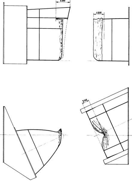
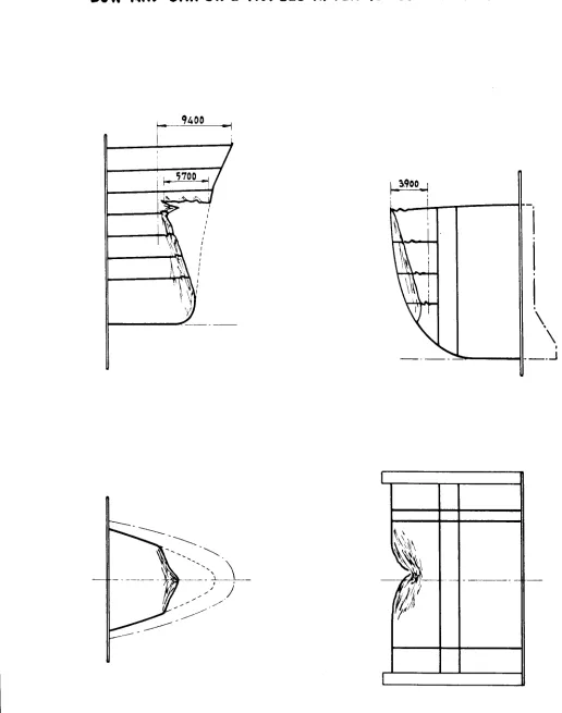
4.1.4 Test No. 5
For test No. 5, the bow and side models chosen were identical to those used in test No. 4, but, while the colliding ship was again assumed to be in full-load condition, the struck ship was considered to be in ballast
(displacement 50,000 tonnes instead of 69,200).
The recorded collision speed was 4.5 m/sec (8.76 knots). The entrained water was 50% of the mass of the struck ship.
The collision energy was entirely absorbed by plastic deformation of the ship side structure to a depth of 6.60 m and by fractures which occurred in the outer shell and in the main deck on both sides of the point where the ship side had been damaged as a result of the collision. These frac-tures reached a limit of about 3.20 m transversely on the deck and of about 7.50 m vertically on the outer shell (full-size ship).
The bow was almost undamaged.
4.t.5
Test No.
6
The objectives of this test were different from those of the preceding and following tests. The aim was to verify whether, after reproducing by means of models all the conditions of an actual collision, the results of
the actual collision and of the model collision could be compared.
The characteristics of the ships that had collided were as follows:
Length Breadth Depth
140 m
18.90
m10.46
mDisplacement (in ballast) 11,000 tonnes Draught at the above displacement
5.60
m Speed at time of collision 10.7 knots Waterline angle of entrance48°
Length Breadth Depth
134 m
19.50
m10.62
mDisplacement (in ballast)
8,500
tonnes Draught at the above displacement4.62
mSpeed at time of collision about 0
Models for this test were built on a 1/10 scale on the basis of original drawings of the two ships.
The angle of impact was fixed at
76°
on the basis of data given in a report on the collision.The relative position of the two models as arranged for the collision test and the damage caused by the collision shock are shown in Figs.
24
and 25.
that to the colliding ship, and was very similar (see Photos 20 and 21), the struck model suffered much less damage than the ship side of the struck ship (see Photos 22 and 23).
This discrepancy between the damage undergone by the struck ship and that
observed in the ship side model can be accounted for by several factors,
the most important ones being:
(a) The speed of the colliding ship might have been higher than that reported by the Captain.
This hypothesis, which could be justified in some cases of collision, would explain the small amount of damage to the ship side model, but cannot account for the fact that the bow damage is at the same time very similar to the actual damage to the colliding ship.
(b) The speed of the struck ship might have been higher than that reported by the Captain.
For obvious reasons, this hypothesis might be more
justi-fied than the previous one.
The fact that the struck ship may have been under way at the moment of impact certainly could explain the more
extensive fracturing of the side plating.
It should be noted that the structure of the ship side model was damaged to a depth of 4 m (full size), but only a small fracture to the side plating occurred, near the bottom of the model and equivalent to a full-size opening 0.30 m wide and 2.10 m high.
(c) The similarity theory between the model and the full-size ship is not completely valid.
The tests carried out by several researchers (see Section 2) were performed with model scales varying from 1/20 to 1/7.5; the results obtained from struck ship side models are satisfactorily equivalent.
However, this lack of validity of the similarity theory would only apply to the ship side structure, since the damage suffered by bow models is generally equal to that caused to the bows of ships that are actually involved in collisions, as can be seen in the photos frequently pub-lished in the technical press.
4.1.6 Test No. 7
The models chosen for this test were identical to those used in test No.
5.
The displacements were also identical, i.e., 69,200 tonnes for the fully laden colliding ship and 50,000 tonnes for the struck ship, which was in ballast. The same collision speed was also adopted (4.5 m/sec or 8.76 knots).It should be pointed out that the carriage holding the ship side model in this test was rigidly mounted to avoid transverse motion after the collision, while in previous tests this motion had been permitted (see Section 3.2).
In this case V was obviously zero. Before testing, it was therefore necessary to consider the mass of water entrained by the struck ship
(50'fo,
as had been calculated after test No.5)
and, consequently, to modify the mass of the colliding model as follows:The mass of the colliding ship is ~:~;00 = 7,050 tonnes
Also
50,000 = 1.51 tonnes
The following formula must then be considered:
m'
2 + m'
2
where m is the modified mass of the colliding model and the other symbols have the notation given in Section
3.2.
In this case:
From the above expression m can be calculated:
= 2.1 2.1 X + 2.26 2.26 = 1.09 tonnes (mass)
The total weight of the carriage carrying the bow was consequently defined as:
1.09 x 9.81 = 10.7 tonnes (weight)
As regards the damages suffered by the models, the results of test No. 7
were thus practically identical to those observed after test No.
5.
Thecolliding bow showed only haavy buckling, while plastic deformations and fractures in the ship side structures absorbed almost all of the colli-sion energy, reaching a depth of 6.60 m (full size). A fracture 9.60 mhigh in the side plating was noted, affecting the main deck transversely for a depth of 3.90 m (full size).
The results of this test are shown in Fig. 26 and Photos 24 and 25.
Comparison of the results of tests No.