© 2016, IRJET | Impact Factor value: 4.45 | ISO 9001:2008 Certified Journal
| Page 1496
LATTICE REDUCTION AIDED DETECTION TECHNIQUES FOR MIMO
SYSTEMS
Susmita Prasad
1, Samarendra Nath Sur
2Dept. of Electronics and Communication Engineering, Sikkim Manipal Institute of Technology, Majhitar, Sikkim,
India
---***---
Abstract -
A Multiple input multiple output (MIMO)technology is seen to provide the best solution to high data rate and reliable wireless communication. For the purpose of detection, Maximum Likelihood receivers are most optimal but highly complex especially with higher order constellation. There are a number of other detectors, linear and non-linear, which are less complex but suboptimal. In this paper we utilize a novel class receivers based on Lattice Reduction for MIMO Systems which achieve near maximum-likelihood detector performance with lower complexity. [1] Lenstra-Lenstra-Lovasz Algorithm [2] is used for lattice reduction purpose. Performance comparisons are made between LRA receivers and other conventional receivers in both independent and correlated channels by simulations. It will be shown that LRA based receivers outperform the conventional ones, especially in correlated channels.
Key Words: MIMO Systems, Zero-Forcing Detection, Minimum Mean Square Error Detection, Wireless Communication, Lattice-Reduction, Maximum-Likelihood Detection, Bit Error Rate
1. INTRODUCTION
There is a huge demand for high data rate wireless communication services which has caused notable research interests in the multiple input and multiple output (MIMO) technologies. In MIMO, a number of independent data streams are simultaneously send over a communication channel by the use of multiple antennas at the transmitter and receiver sides in a rich scattering environment. Each receiving antenna acquires a superimposition of all of these transmitted streams. The process of separating out each independent data streams is called the MIMO detection. [3]
A brute-force Maximum-Likelihood (ML) detection provides optimal solution to the MIMO symbol detection [4], but its implementation is highly complex especially with either a larger size constellation or large number of antennas. Therefore, the real challenge lies in designing the hardware for the MIMO symbol detectors such that bit-error-rate (BER) performance comparable to the ML detector is achieved while having low hardware complexity and high throughput. Many low-complexity methods like Zero-Forcing (ZF) and Minimum Mean Square Error (MMSE) detection exhibits considerably lower complexity which map well to hardware but have greatly reduced BER performance compared to the ML detector. [5] It is clearly desirable to explore detection algorithms that achieve ML or near-ML performance.
Lattice reduction (LR)-aided detectors incorporate lattice reduction algorithms into the algorithms of ZF or MMSE detectors.[6] For L-R aided MIMO detection, the Lenstra-Lenstra-Lovasz algorithm has been used exclusively till date. The LLL reduction is used to improve the performance of the MIMO detection schemes. The algorithm optimizes the generating matrix of the lattice, to obtain a nicer description of the lattice. [7] As of now many research papers have shown the utilization of LLL algorithm for the purpose of lattice reduction. Few of these papers include ‘Lattice Reduction Aided Detection for MIMO-OFDM-CDM Communication Systems’ by J. Adeane, M.R.D. Rodrigues and I.J.Wessel and ‘Lattice-Reduction-Aided Receivers for MIMO-OFDM in Spatial Multiplexing System’ by Inaki Berenguer, Jaime Adeaner, Ian J. Wassell and Xiaodong Wang.
© 2016, IRJET | Impact Factor value: 4.45 | ISO 9001:2008 Certified Journal
| Page 1497
channels are correlated, LRA significantly outperformsother suboptimal detectors in terms of BER.
2. SYSTEM MODEL
Let us consider a MIMO Communication system
[image:2.595.35.282.298.516.2]where is the number of transmit antennas and is the number of receive antennas. The data symbol is de-multiplexed into data symbols and then mapped onto rectangular QAM symbols. The modulated data stream is now simultaneously transmitted over antennas over a rich scattering channel.
Figure 1: MIMO System [8]
It is possible to relate the received data vector to
the transmitted data vector as
This is the baseband model where the received data
vector
,
transmitted
data
vector
,noise vector
and
is the
matrix of complex flat fading channel coefficients
between transmit and receive antennas.
is
modelled as a zero mean white Gaussian random
vector with covariance matrix
.[9]
Since
are complex valued we can
equivalently write
………(2) .
This gives us the real model of the form:
………(3)
2.1 LRA DETECTION
In LRA detection, the channel matrix
is
considered as the generator matrix of some lattice.
The columns of the channel matrix are generator
basis of this lattice.
Let
be defined as
=
…...(4)
Here the disadvantage of
is that the receiver
signal easily falls out of its decision region by even a
small amount of noise if the basis vectors of
is
highly correlated i.e. the angle between the vectors
is very narrow. Therefore there is a need of Lattice
Reduction whose supreme goal is to transform the
generator matrix
of the lattice to another
generator matrix
of that same lattice by
finding out the change of basis .
………(5)
The new generator matrix
can now be
designed to be near orthogonal such that it
improves the reliability of many low-complexity
suboptimal detectors. There are many existing LR
algorithms that help in achieving this.
© 2016, IRJET | Impact Factor value: 4.45 | ISO 9001:2008 Certified Journal
| Page 1498
2.2 ZF AND MMSE ALGORITHMS
At the receiver,
. In order to detect
the message, we perform inverse operation,
……(6). Thus the simple
receiving consists of the inverting of channel matrix
along with an extra term
. But its inverse
modelling is difficult as the inverse exists only
when the matrix is square. Therefore, we define a
generalized inverse considering
. Two of
these approaches are discussed below :
In case of zero forcing detection technique, we
choose the minimum error vector from among all
the possible transmit vectors , i.e. is to be
selected in such a way that error
is
minimized. [11]
On vector differentiation we get,
……(7)
This is the approximate solution which minimizes
the error called the Least Square Error Solution.
For complex channel matrix,
……(8)
where
is the pseudo
inverse of .
Zero Forcing suffers from noise amplification
especially when the number of transmitters and
receivers are same. This can be shown with the
example of Single Input and Single Output System.
Let us say,
Inverse modelling will result in
………(10)
If the value of h is small (
), the noise blows
up causing instability.
The minimum mean square error detection takes
noise into account and thereby leading to improved
performance
and
elimination
of
noise
enhancement. The estimate of the transmitted
vector at the MMSE receiver is given by
…….(11)
where
is the transmitted data power and
is
the noise power at the receiver.
Equivalently, can be expressed as
……..(12)
At very high SNR,
[12] This is
nothing but the transmit vector estimate of ZF
receiver. So we can say that ZF is the limiting form
of MMSE for SNR approaches to infinity. [13]
2.3 LLL ALGORITHMS
Lenstra-Lenstra-Lovasz Algorithm is a popular
Lattice Reduction aided detection algorithm named
after its founder whose running time is polynomial
in the dimension of the lattice. [14]
Implementation of LLL lattice reduction
[15]
Input: Lattice Basis
While
do
do
;
% Compute
% Exchange
% final result
© 2016, IRJET | Impact Factor value: 4.45 | ISO 9001:2008 Certified Journal
| Page 1499
3. SIMULATIONS AND RESULTS
In this paper all the results are simulated using MATLAB software. Basically this paper represents the comparative study of different receiver system under correlated channel condition.
5 10 15 20 25 30
10-4
10-3
10-2
10-1
100
Average SNR per receive antenna [dB]--->
b
it
e
rr
o
r
ra
te
(
B
E
R
)-
-->
[image:4.595.318.560.145.349.2]ZF MMSE LLL-ZF LLL-MMSE
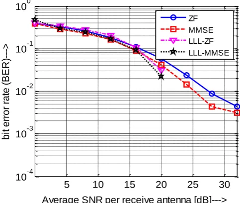
Figure 1: BER Performance of a 4 × 4 MIMO System with uncorrelated channels and QPSK modulation.
This figure represents the study of BER performance of LLL receivers and conventional receivers with the system being QPSK modulated and having uncorrelated channels.
We observe that as the SNR increases, the BER of the receivers decrease.
It is also observed that the LRA receivers have better BER performance than the conventional receivers.
Table 1: Comparison of BER performance of linear and LRA aided receivers
Receiver To obtain BER 0.01
SNR required in dB
ZF 22.94
MMSE 18.98
LLL-ZF 16
LLL-MMSE 14.84
LLL-MMSE outperform ZF and MMSE receivers by 8.1 dB and 4.14 dB respectively at 0.01 BER. LLL-ZF outperform
ZF and MMSE receivers by 6.94 dB and 2.98 dB respectively at 0.01 BER.
5 10 15 20 25 30
10-4
10-3
10-2
10-1
100
Average SNR per receive antenna [dB]--->
b
it
e
rr
o
r
ra
te
(
B
E
R
)-
-->
[image:4.595.40.267.252.434.2]ZF MMSE LLL-ZF LLL-MMSE
Figure 2: BER Performance of a 4 × 4 MIMO System with uncorrelated channel and 16QAM Modulation.
This figure represents the study of BER performance of LLL receivers and conventional receivers with the channels being uncorrelated and system being 16QAM modulated.
It is observed that as the SNR increases, the BER of the receivers decrease. We observe that the LLL receivers have better BER performance than the conventional receivers.
Table 2: Comparison of BER performance of linear and LRA aided receivers
Receiver To obtain BER 0.03 the
SNR required in dB
ZF 22.87
MMSE 21.15
LLL-ZF 19.97
LLL-MMSE 19.1
[image:4.595.309.567.568.653.2] [image:4.595.31.278.628.727.2]© 2016, IRJET | Impact Factor value: 4.45 | ISO 9001:2008 Certified Journal
| Page 1500
Table 3: Comparison of BER curves of receivers for QPSKmodulated and 16QAM modulated systems
Receivers To obtain BER 0.03
SNR required by
a QPSK
modulated system (in dB)
SNR required by
a 16QAM
modulated system (in dB)
ZF 18.16 22.87
MMSE 15.02 21.15
LLL-ZF 13.67 19.97
LLL-MMSE 13.02 19.1
[image:5.595.313.558.259.386.2]This table represents comparison between figure 1 and figure 2 i.e. performance of the receivers when the size of the constellation is increased.
We observe that as the constellation is increased from QPSK to 16QAM, SNR required for LLL-MMSE receiver to achieve a BER of 0.03 increases by 6.08dB. Also, similarly in case of ZF receiver 4.71dB increment in SNR is required for getting 0.03 BER.
It can be concluded that as the size of the constellation is increased the BER performance of the receivers degrades.
5 10 15 20 25 30 35
10-4
10-3
10-2
10-1
100
Average SNR per receive antenna [dB]--->
B it e rr o r ra te ( B E R )- --> ZF MMSE LLL-ZF LLL-MMSE BER Curves for correlation coefficient = 0.5 BER Curves for correlation coefficient = 0.0
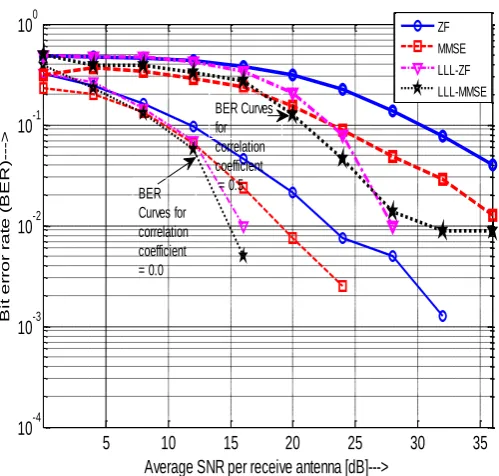
Figure 3. BER Performance of a 4 × 4 MIMO QPSK System with correlation coefficients of the channel as 0.0 and 0.5.
This figure shows the comparison of BER performances of the receivers when the correlation coefficient of the channel is increased (here from 0.0 to 0.5) and when the system is QPSK modulated.
We observe that as the correlation coefficient of the channel increases, the BER performance of the receivers degrades.
Table 4. Comparison of BER curves of receivers with correlation coefficients 0.0 and 0.5
Receivers To obtain BER 0.04
SNR required by a system having correlation coefficient of 0.0
SNR required by a system having correlation coefficient of 0.5
ZF 16.67 35.8
MMSE 13.9 29.31
LLL-ZF 13.1 25.3
LLL-MMSE 12.55 24.46
As the correlation coefficient of the channel is increased from 0.0 to 0.5 the SNR required by a LLL-MMSE receiver to obtain 0.04 BER increases by 11.91 dB. Also, for a ZF receiver this requirement is 19.13dB.
5 10 15 20 25 30
10-4 10-3 10-2 10-1 100
Average SNR per receive antenna [dB]--->
b it e rr o r ra te ( B E R )- --> LLL-ZF LLL-MMSE Correlation Coefficient = 0.1 Correlation Coefficient = 0.0 Correlation Coefficient=0.7 Correlation Coefficient = 0.5
Figure 4: BER Performance of a 4 × 4 MIMO QPSK System with correlation coefficients of the channel as 0.0, 0.1, 0.5 and 0.7
[image:5.595.314.581.463.685.2] [image:5.595.39.289.467.705.2]© 2016, IRJET | Impact Factor value: 4.45 | ISO 9001:2008 Certified Journal
| Page 1501
correlation coefficients – 0, 0.1, 0.5 and 0.7 and QPSKmodulation.
We observe that more correlated the channel, lesser is the BER performance of the receiver.
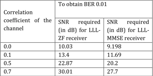
Table 5. Comparison of BER curves of ZF and LLL-MMSE receiver for increasing values of correlation coefficients
Correlation coefficient of the channel
To obtain BER 0.01
SNR required (in dB) for LLL-ZF receiver
SNR required (in dB) for LLL-MMSE receiver
0.0 10.03 9.198
0.1 13.4 11.69
0.5 22.87 20.2
0.7 30.01 27.7
At BER 0.01 and channel correlation coefficient 0.7, LLL-MMSE outperforms LLL-ZF receiver by 2.31 dB.
Also, as the correlation of the channel is increased from 0.1 to 0.7, the SNR requirement by the LLL-MMSE receiver increases by 16.01 dB to obtain BER 0.01.
4. CONCLUSIONS
In this paper, we have investigated several detection schemes for MIMO Communication Systems. We have used Lenstra-Lenstra-Lovasz algorithm for lattice reduction. We can conclude from the simulation results that LRA receivers outperforms the traditional linear receivers. Performance of the LRA receivers is found close to that of ML receivers. This shows that the LLL algorithm has capability of improving BER performance of conventional receivers.
REFERENCES
[1] Inaki Berenguer, Jaime Adeaner, Ian J. Wassell and Xiaodong Wang, ‘‘Lattice-Reduction-Aided Receivers for MIMO-OFDM in Spatial Multiplexing System’’, Personal, Indoor and Mobile Radio Communications, 2004. PIMRC 2004. 15th IEEE International Symposium on, On pages: 1517 - 1521 Volume 2, 5-8 Sept. 2004
[2] Chiao-En Chen, ‘‘A New Lattice Reduction Algorithm for LR-aided MIMO Linear Detection’’,
in
IEEE Transactions on Wireless Communications, On pages 2417 – 2422 Volume:10 , Issue: 8, 23 June 2011[3] Brain J. Gestner, ‘‘Lattice Reduction for MIMO detection : From theoretical analysis to hardware realization ’’, PhD dissertation, School of Electrical and Computer Engineering, Georgia Institute of technology, May 2011
[4] C. Windpassinger and R. F. H. Fischer, ‘‘Low-Complexity Near-Maximum-Likelihood Detection and Precoding for MIMO Systems using Lattice Reduction’’, in Proc. IEEE Information Theory Workshop(ITW), Paris, France, March 2003
[5]J. Adeane, M.R.D. Rodrigues and I.J.Wessel, “Lattice Reduction Aided Detection for MIMO-OFDM-CDM Communication Systems”, IET Communications, Pages 526 – 531 Volume 1 Issue 3, June 2007
[6] Dirk Wubben, Ronald Bohnke, Volker Kuhn and Karl-Dirk Kammeyer, “MMSE-BASED LATTICE-REDUCTION FOR NEAR-ML DETECTION FOR MIMO SYSTEMS’’, Communications, 2004 IEEE International Conference on, On pages: 798 - 802 Vol.2, 20-24 June 2004
[7]Christoph Windpassinger, Lutz H. -j. Lampe, Robert F. H. Fischer, ‘‘From Lattice Reduction-Aided Detection towards Maximum-Likelihood Detection’’, in MIMO system, in Proceedings of WOC, 2003
[8]http://www.wcsg.ieiit.cnr.it/research/activity/MI-C-MIMO.html
[9]Ying Hung Gan, and Wai Ho Mow, ‘‘Complex Lattice Reduction Algorithm for Low-Complexity MIMO Detection’’, IEEE Transactions on Signal Processing (Volume:57 , Issue: 7 ), On pages:
2701 – 2710, 24
February 2009
[10]Advanced 3G and 4G Wireless Communication, NPTEL National Program on Technology Enhanced Learning, Prof. Aditya K. Jagannatham: MIMO MMSE Receiver and Introduction to SVD 2013 [Online].
Available : https://youtu.be/aQqgMcSviko [Accessed: 22- Feb- 2015]
[11] Advanced 3G and 4G Wireless Communication,
NPTEL National Program on Technology Enhanced Learning, Prof. Aditya K. Jagannatham: MIMO System Model and Zero-Forcing Receiver 2013 [Online].
Available : https://youtu.be/1_-9tbFNsPk [Accessed: 21- Feb- 2015]
[12]Advanced 3G and 4G Wireless Communication, NPTEL National Program on Technology Enhanced Learning, Prof. Aditya K. Jagannatham: CDMA Near-Far Problem and Introduction to MIMO 2013 [Online].
Available : https://youtu.be/p8uQz_3U1CA. [Accessed: 20- Feb- 2015]
[image:6.595.30.286.207.334.2]© 2016, IRJET | Impact Factor value: 4.45 | ISO 9001:2008 Certified Journal
| Page 1502
communication systems", Vehicular TechnologyConference, 2004. VTC2004-Fall. 2004 IEEE 60th, On page(s): 1604 - 1608 Vol. 3 Volume: 3, 26-29 Sept. 2004 [14] H. Yao and G.W. Wornell. ‘‘Lattice-reduction-aided detectors for MIMO communication systems.’’ In Proc.
IEEE Globecom, pages 424-428, Taipei, Taiwan, Nov. 2002.
![Figure 1: MIMO System [8]](https://thumb-us.123doks.com/thumbv2/123dok_us/8202368.815932/2.595.35.282.298.516/figure-mimo-system.webp)