© 2016, IRJET | Impact Factor value: 4.45 | ISO 9001:2008 Certified Journal | Page 1888
Study of Power system performance with Interline power flow
controller (IPFC) by using software and lab prototype
Vaishali M. More
1,Dr. Vinod Chandrakar
21
G.H.Raisoni college of Engineering Nagpur
2
Professor,Dept.of Electrical Engineering, G.H.Raisoni college of Engineering Nagpur, Maharashtra,India
---***---Abstract -
In the power system, the price of thetransmission lines is an important factor in the network company. An interline power flow controller (IPFC) is a grouping of series and series converter based FACTS controller which has the ability of controlling power flow among multiple lines in the same network of the transmission line. This paper is based on the performance of multi-machine system and system is studied with & without interline power flow controller (IPFC) under different environments. The IPFC is designed to limit the power transferring across lines and minimize the oscillations during disturb condition. Series FACTS devices are mainly used to limit the flow of power, minimize the disturbances and improving transient stability of the system. Simulation is done by using MATLAB software.
Key Words: FACTS, IPFC, transient stability
1.INTRODUCTION
Series FACTS devices are used for limiting the power transfer in transmission lines and for minimizing the disturbances present in power system. Static synchronous series compensator (SSSC) injects the voltages or absorbs voltages from transmission line where it is connected. When it is fed with some supplementary signals from the connected system, SSSC has the ability to damp the oscillation by changing the compensated reactance of the transmission line [1] ,[3] and [6]. Synchronous voltage source, implemented by gate turn-off thyristor (GTO) based voltage sourced inverter, provides controllable series compensation. SSSC also provides controllable compensating voltage over an identical compensating voltage over identical capacitive and inductive limits which is not dependent on the magnitude of the line current[4]. A combined multi-pulse and multilevel inverter method for high power applications has been proposed in [5].
The [7 ] presents the importance and difference of an optimal direct and indirect adaptive neuro-fuzzy control scheme to limits the disturbances using the SSSC. A hybrid adaptive neuro-fuzzy B-spline wavelet-based control technique was used in a multi-machine power system for controlling disturbances. The [12 ] paper limits the inter-area oscillations in a multi-machine power system. The
feasibility of the proposed technique is checked by using PSCAD simulation program and paper shows that IPFC work better than SSSC under same condition.
Day-by-day consumption of electricity goes on rising. To meet with that increased power level it is not possible to replace all old power plants. So some technology has to be combined with old power system to increase the power transfer across the transmission lines. The FACTS devices are best solution for compensation of this problem. The interline power flow controller (IPFC) is a series connected voltage source converter (VSC)- based flexible ac transmission system (FACTS) controller for management of power flow among the multiline transmission system of a substation. IPFC is one of the latest generation FACTS controllers to control power flow. IPFC device is designed by Gyugyi with Sen Schaulder in 1998, for solving the problem of controlling a number of transmission lines at a time in plant. IPFC scheme gives independently reactive series compensation of each individual and has the capability to transfer real power between the compensated lines.
2.
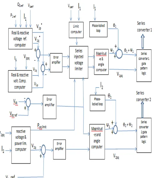
CONTROL SCHEME FOR IPFC
© 2016, IRJET | Impact Factor value: 4.45 | ISO 9001:2008 Certified Journal | Page 1889
Fig-1. Basic control scheme for two converter IPFC
2.2 System model
The system consists of four machines forming two areas in which two generators are connected in each area as shown in fig. 2. These two areas are connected together with the help of parallel transmission lines each having capacity of 500kv and 220 km long . System contain the load L1. The power is measured at various buses. Voltage is injected by IPFC in system . The detail of multi-machine is given in Table A.
Fig-2. Multi-machine system with IPFC FACTS device
3.
SIMULATION RESULTS
Multi-machine system is validated by using MATLAB simulink under various cases.
Case 1:- Normal load condition
Fig-3. System without IPFC Under normal load condition Rotor angle remain steady state. Accelerating power is zero and voltages remain 1 pu in system.
Fig-4. Power of system without IPFC
Active power and reactive power across buses B-1 is 942 MW & -124 Mvar, B-2 is 471 MW & -62 Mvar and B-6 is 471MW & -62 Mvar respectively .
Fig-5. System with IPFC under normal load condition.
[image:2.595.42.290.101.387.2] [image:2.595.314.561.305.457.2] [image:2.595.318.554.509.653.2] [image:2.595.36.272.531.648.2]© 2016, IRJET | Impact Factor value: 4.45 | ISO 9001:2008 Certified Journal | Page 1890
Fig-6. Power with IPFC under normal load conditionActive power and reactive power across buses B-1 is 942 MW & -28 Mvar, B-2 is 710 MW & -28 Mvar and B-6 is 232 MW & -56 Mvar respectively . The power flowing across the bus B-2 is increased from 471 MW to 710 MW.
Case 2 :- Under 10% increased load condition
Fig-7. System without IPFC
Rotor angle takes large time to settle down to it’s steady-state value as shown in figure 7.
Fig-8. Power of system without IPFC
Active power across the buses also takes large time to settle down to steady-state value.
Fig-9. system with IPFC under increased load condition Rotor angle reach to the steady state value in minimum time as shown in figure9.
Fig-10. Power of system under 10% increased load condition
Power across the buses reach to steady state values in increased load demand and also fulfils the demand.
Case3:- Under fault condition
Fault type L-L-L-G in area 1 near bus 1. Fault occurring time is 1 sec. and clearing time 1.02 sec.
Fig-11. System without IPFC under fault condition. Rotor angle reach to the steady state value after fault clearing. Accelerating power is zero. Voltage is 1 pu as shown in figure 11.
Fig-12. Power of system without IPFC
© 2016, IRJET | Impact Factor value: 4.45 | ISO 9001:2008 Certified Journal | Page 1891
Fig-13. System with IPFC under fault conditionFault occurs at 1 second and remain for 0.02 seconds in the system. Rotor angle reach to steady state value after fault clearing as shown in figure 13. The accelerating power is zero after fault clearing and voltage is 1 pu.
Fig-14. Power of system with IPFC under fault condition. During fault condition peak reduced by (1150 - 1128 = 22MW) nearly 2% after installing IPFC FACTS device in system as shown in figure 14.
4. LAB PROTOTYPE
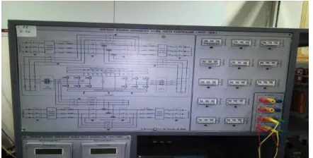
The panel available in the FACTS Lab of Electrical Department shown in fig.15. is designed to study various VSC based FACTS devices . The FACTS devices which are form through this panel are STATCOM, SSSC, UPFC and IPFC by arranging switches status.
With the help of this panel, detailed study of IPFC is done. Through this panel we understand the importance of presence of IPFC in the system for efficient power transfer.
Fig-15. Transmission line simulator module
Fig-16. Block diagram
For IPFC switches S2, S3, S4, S5,S7,S8,S9,S10,S11,S12 are closed while for SSSC switches S2, S3, S4 and S5 are closed. The receiving end voltages are observed when one SSSC is ON and IPFC is ON.
1.1.Static synchronous series compensator 1 is ON Load = 150 ohm , I = 80 mA
V1 = V2 = 90%
Receiving end voltage (Vr)
VRY = 8.7 volt
VYB = 8.7 volt
VRB = 8.9 volt
α 1 (degree) V1 (volt)
180 (lag) 9
160(lag) 9
149(lag) 9
120(lag) 9
113(lag) 8.9
74(lag) 8.9
0 (lead) 9.0
[image:4.595.50.293.326.426.2]142(lead) 9.0
[image:4.595.35.256.606.718.2]© 2016, IRJET | Impact Factor value: 4.45 | ISO 9001:2008 Certified Journal | Page 1892
Receiving end voltage (Vr)VRY = 34.8 volt
VYB = 33 volt
VRB = 36.2 volt
α 1(degree) V1 (volt)
180 (lead) 36.2
166(lead) 36.3
150(lead) 36.2
120(lead) 36.2
93(lead) 36.3
54(lead) 36.4
50 (lead) 36.3
8(lead) 36.2
14 (lag) 36.1
21 (lag) 36.3
29 (lag) 36.3
36 (lag) 36.2
45 (lag) 36.4
90 (lag) 36.1
104 (lag) 36.2
122 (lag) 36.3
142 (lag) 36.1
159 (lag) 36.0
162 (lag) 36
180 (lag) 35.9
5.
CONCLUSIONS
The IPFC is the combination of two or more than two
SSSC connected together via DC link. Each SSSC provide the reactive power compensation to the individual line. IPFC hasthe ability of supplying the real power from lightly- loaded
line to the overloaded line through a common dc link. Rotor angle indicates steady state condition under no
[image:5.595.312.561.265.417.2]fault condition. System with IPFC achieve steady state value in increased load demand within short time as compared to system without IPFC . During fault condition first peak reduced significantly after installing IPFC FACTS device in system. System parameters reach to steady state value after fault clearing. From the lab prototype we can conclude that receiving end voltages improved in IPFC as compared to SSSC FACTS device for same load. For various firing angle receiving voltage V1 is calculated.
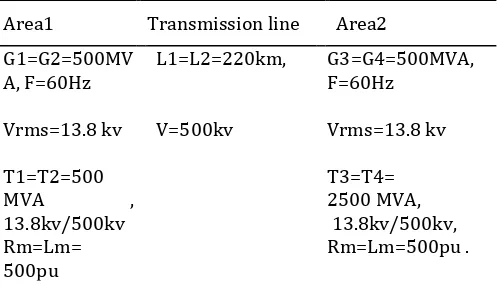
Table A :- Multi-machine system data
Area1 Transmission line Area2 G1=G2=500MV
A, F=60Hz L1=L2=220km, G3=G4=500MVA, F=60Hz
Vrms=13.8 kv V=500kv Vrms=13.8 kv
T1=T2=500
MVA ,
13.8kv/500kv Rm=Lm= 500pu T3=T4= 2500 MVA, 13.8kv/500kv, Rm=Lm=500pu .
REFERENCES
[1] N.G.Hingorani and L.Gyugyi, “Understanding facts concepts and technology of flexible ac transmission system”, New York, NY: IEEE press, 2000.
[2] M. Klein, G.J. Rogers, P. Kundur, “ A fundamental study of inter-area oscillations in power systems”, IEEE Transactions on power systems, Vol. 6, No. 3, August 1991.
[3] Chi Su, ZheChen ,“Damping inter-area oscillations using static synchronous series compensator (SSSC)”, UPEC 2011, 46th International Universities Power Engineering Conference, 5-8 September 2011 , Soest , Germany.
[4] Laszlo Gyugyi, Colin D. Schauder, Kalyan K. Sen, ”Static synchronous series compensation : a solid-state approach to the series compensation of transmission lines”, IEEE transaction on power delivery, vol.12 ,no.1, January 1997. [5] B. Geethalakshmi and P. Dananjayan, “A combined multipulse-multilevel inverter based SSSC”, 2009 third international conference on power system, Kharagpur, INDIA, December 27-29.
[6] Cao Taibn, HouRui, Qian Bifu, “The design of nonlinear control strategy for sssc based on constant voltage control”, 2011 IEEE conference.
© 2016, IRJET | Impact Factor value: 4.45 | ISO 9001:2008 Certified Journal | Page 1893
[8] Laszlo Gyugyl, Kalyan K. Sen, Colin D. Schauder, “Theinterline power flow controller concept: a new approach to power flow management in transmission systems”, IEEE Transactions on Power Delivery, Vol. 14, No. 3, July 1999, Page no. 1115-1122.
[9] J.Muruganandham , Dr.R.Gnanadass ,” Performance analysis of interline power flow controller for practical power system”, 2012 IEEE Students, Conference on Electrical, Electronics and Computer Science.
[10] Jianhong Chen, Tjing T. Lie, D.M. Vilathgamuwa, “Basic control of interline power flow controller”, 2002 IEEE conference.
[11] A. V. Naresh Babu & S. Sivanagaraju ,”Mathematical modelling ,analysis and effects of interline power flow controller (ipfc) parameters in power flow studies”, 2011 IEEE conference.
[12] Ahmet Mete VURAL ,Kamil Cagatay BAYINDIR ,” Optimal IPFC damping controller design based on simplex method and self tuned fuzzy damping scheme in a two-area multi machine power system ”, Turkish Journal of electrical engineering and computer science , pulished online on 17 Sept. 2015 and printed on 28 August 2015.
[13]George Terzakis,” Introduction to C Programming with the TMS320LF2407ATM DSP Controller George”, New Age International.