SIMULATION OF MPC BASED SPEED CONTROL OF
PERMANENT MAGNET SYNCHRONOUS MOTOR DRIVE
1 S.SIVARANJANI, 2Dr.R.RAJESWARI
1Asstt. Prof., Department of Electrical and Electronics Engineering, VSB Engineering College, Karur
2
Asstt. Prof., Department of Electrical Engineering, Government College of Technology, Coimbatore
E-mail: [email protected], [email protected]
ABSTRACT
This paper describes the implementation of an optimal control strategy used for speed control of Permanent Magnet Synchronous Motor (PMSM) drive. Since several decades Power Electronics and Drives deals with cascaded control, which provides easy implementation and robust in operation. A serious drawback of requiring fast operating inner loop looks forward a strong candidate to eliminate the drawback. The Model Predictive Controller cost function enables a simple, flexible and improved performance controller for the drive. The basic concepts, operating principles, control diagrams, and results are used to provide a comparison between the different control strategies. Several key aspects related to this methodology are, in depth, presented and compared with conventional control technique. The performance of the motor drive with the proposed controller results is found to be prominent.
Keywords: Speed Control, PMSM, MPC, PWM Inverter
1.
INTRODUCTIONPermanent Magnet Synchronous Motors (PMSMs) have been widely used in many of the industrial applications due to its high performance compared with other electrical motors. Advantages of PMSM drives over other drives are higher power factor operation, higher torque to inertia ratio and higher efficiency. In recent years, new control strategies have been studied for the current control of power inverters. Among them, model predictive control (MPC) has been applied for the control of power converters due to its several advantages, like fast dynamic response, easy inclusion of nonlinearities and constraints of the system, and the flexibility to include other system requirements in the controller [1]. MPC considers a model of the system in order to predict the future behavior of the system over a horizon in time. A cost function represents the desired behavior of the system.
MPC is an optimization problem where a sequence of future actuations is obtained by minimizing the cost function. The first element of the sequence is applied, and all the calculation is repeated every sample period. Due to the fast sampling times used in the control of power converters, solving the optimization problem of MPC online is not practical. One approach is to use an explicit solution of MPC, solving the
optimization problem offline. The resulting controller is a search tree or a lookup table and can be implemented without big computational effort. This solution has been used for the control of a DC–DC converter [2] and a drive system [3].
Considering that power converters are systems with a finite number of states, given by the possible combinations of the state of the switching devices, the MPC optimization problem can be simplified and reduced to the prediction of the behavior of the system for each possible state. Then, each prediction is evaluated using the cost function, and the state that minimizes it is selected [4]. This is also a different approach that has been successfully applied for the current control in a three-phase inverter [1], [5] and a matrix converter [6], [7], power control in an active front-end rectifier [8], and torque and flux control of an induction machine [9]–[12].
2.
PMSM MODELLINGwinding has been developed on rotor reference frame using the following assumptions:
• Saturation is neglected.
• The induced EMF is sinusoidal.
• Eddy currents and hysteresis losses are negligible.
• There are no field current dynamics.
With these assumptions, the stator Voltage d, q equations of the PMSM in the rotor reference are given by:
f
ϕ
ω
ω
r d d rq q q s
q
=
R
i
+
L
pi
+
L
i
+
V
(1)q d r d d d s
d
=
R
i
+
L
pi
-
L
i
V
ω
(2)where id, iq, vd, vq, Ld and Lq are the d and q axis currents, voltages and inductances respectively. Rs
is the stator resistance, φf is the flux induced by
rotor on stator windings, Te is the electromagnetic torque and ωr is the angular velocity of the rotor. Also flux Linkages are given by
f
ϕ
ϕ
d=
L
di
d+
(3)q q q
=
L
i
ϕ
(4)where φd and φq are flux linkages in d and q axis
respectively.
The developed torque motor is being given by
]
i
i
)
L
-L
(
-i
[
(P/2)
(3/2)
=
T
eϕ
f q d q d q (5)The mechanical Torque equation is
J
+
B
+
T
=
T
e Lω
m pω
m (6)In the above equations P is the number of Poles, TL
is the Load torque, B is the Friction coefficient and JP is the moment of inertia. Solving for the rotor
mechanical speed
(P/2)
=
mr
ω
ω
(7)In the above equations ωr is the rotor electrical
speed where as ωm is the rotor mechanical speed.
The model equations of PMSM can be rearranged in the form of following first order differential equations are m m m m m L e m q f r d d r q s q q d q q r d s d d = = p J / ) B -T -T ( = p L / ) -i L -i R -V ( = i p /L ) i L + i R -(V = i p
∫
ω
θ
ω
θ
ω
ω
ϕ
ω
ω
ω
(8)θm is the position angle of rotor. pid and piq are
differential d and q axis currents respectively. In order to achieve maximum torque per ampere and maximum efficiency with linear characteristics, direct axis current component id forced to zero and the reluctance torque is zero.
q f
e
=
(3/2)
(P/2)
i
T
ϕ
(9)The d, q variables are obtained from a, b, c variables through the park transform as
/3)]
2
+
sin(
V
+
/3)
2
-sin(
+V
sin
2/3[V
=
V
/3)]
2
+
cos(
V
+
/3)
2
-cos(
V
+
cos
2/3[V
=
V
c b a d c b a qπ
θ
π
θ
θ
π
θ
π
θ
θ
(10)The a, b, c variables are obtained from the d, q variables through the inverse of the park transform as
/3)
2
+
sin(
V
+
/3)
2
+
cos(
V
=
V
/3)
2
-sin(
V
+
/3)
2
-cos(
V
=
V
sin
V
+
cos
V
=
V
d q c d q b d q aπ
θ
π
θ
π
θ
π
θ
θ
θ
(11)The torque equation is similar to that of separately excited DC motor, and this completes the transformation of a PMSM to an equivalent separately excited DC motor.
3. INVERTER TOPOLOGY
In this simulation model, PMSM is fed by a current controlled PWM inverter is built by using six power semiconductor devices. The PWM current controllers are widely used. The switching frequency is usually kept constant. They are based in the principle of triangular carrier wave of desire switching frequency and is compared with the error of controlled signal. The error signal obtained from the sum of reference signal generated in the controller and the negative of the actual motor current feedback from the motor. The voltage signal obtained triggers the gates of the voltage source inverter to generate the desired output. If the error command is greater than the carrier, the inverter leg is held switched to the positive polarity. When the error command is less, the inverter leg is switched to negative polarity. This will generate the PWM signal and the output voltage of the inverter is proportional to the current error command.
4. MODEL PREDICTIVE ALGORITHM
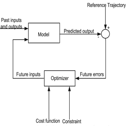
The main idea of predictive control is to use a model of the plant to predict future outputs of the system. Based on this prediction, at each sampling period, a sequence of future control values is elaborated through an on-line optimization process, which maximizes the tracking performance while satisfying constraints.
Figure 1 A Simple Block Diagram Describing The MPC
Only the first value of this optimal sequence is applied to the plant, the whole procedure is repeated again at the next sampling period according to the ‘receding’ horizon strategy. A simple block diagram characterizing the MPC is shown in Figure 1. It should be noted that the predicted output from the system model and the actual error are used to obtain the control signal. Model predictive control is based on the system model and the principles of receding horizon control (RHC).
The control signal at instant t is obtained by solving, at each sampling instant, an on line open loop optimal control problem over a finite horizon using the current state of the system as initial states. The interesting of this control technique becomes obvious when the trajectory to be followed by the system is known in advance, as for example in the robot, chemical process or machine tools, where the anticipation action takes place. The general object is to tighten the future output error to zero, with minimum input effort. The cost function to be minimized is generally a weighted sum of square predicted errors and square future control values, e.g. in Generalized Predictive Control.
(
)
[
( 1)]
2) (
2
) ( ) ( ) ( ,
,
1
2
1 2
1
∑ + −
+
∑
=
+ − + ∧ =
=
u u
N
j k u j N
N j
j k w j k y j N
N N J
j
λ
β (12)
where N1, N2 are the lower and upper prediction horizons over the output, Nu is the control horizon, β ( j),λ(j) are weighting factors. The control horizon permits to decrease the number of calculated future control according to the relation: ∆u(k + j) = 0 for j
≥ Nu . w(k + j) represents the reference trajectory over the future horizon N .Constraints over the control signal, the outputs and the control signal changing can be added to the cost function:
max min
u
(
k
)
u
u
≤
≤
max min
u
(
k
)
u
u
≤
∆
≤
∆
∆
(13)max min
y
(
k
)
y
y
≤
≤
Model Predictive Control have many advantages, in particularly it can pilot a big variety of process, being simple to apply in the case of multivariable system, can compensate the effect of pure delay by the prediction, inducing the anticipate effect in closed loop, being a simple technique of control to be applied and also offer optimal solution while respecting the given constraints. On the other hand, this type of restructure required the knowledge of model for the system, and in the present of constraints it becomes a relatively more complex regulator than the PID for example, and it takes more time for on-line calculations when the constraints intervene. MPC parameters, including prediction and control horizon as well as weighting factors, are designed based on successive iterations (trial and error); no mathematical or theoretical forms have been developed yet to determine the best configuration of MPC parameters.
5. CONVENTIONAL CONTROLLER
Figure 2 Conventional DTC Speed Controller
Closed Loop speed control systems have fast response, but become expensive due to the need of feedback components such as speed. For a conventional PM motor drive system with a full speed range the system will consist of a motor, an inverter and a controller sensor. Speed control of motors mainly consist of two loops the inner loop for current and the outer loop for speed as shown in Figure 2.
The order of the loops is due to their response, how fast they can be changed. This requires a current loop at least 10 times faster than the speed loop. Since the PMSM is operated using field oriented control, it can be modeled like a DC motor. The design begins with the innermost current loop by drawing the block diagram. But in PMSM drive system the motor has current controllers which make the current loop. The current control is performed by the comparison of the reference currents with the actual motor currents.
6. PROPOSED MPC CONTROLLER
The main goal of this controller is to provide the optimal 3-phase primary voltages necessary for tracking a certain speed reference trajectory. Moreover, constraints over the flux and current could be imposed to keep them within permissible values. The main idea is to tighten the future output error to zero, with minimum input effort. The MPC controller produces its optimal output derived from a quadratic cost function minimization based on the linearized machine model.
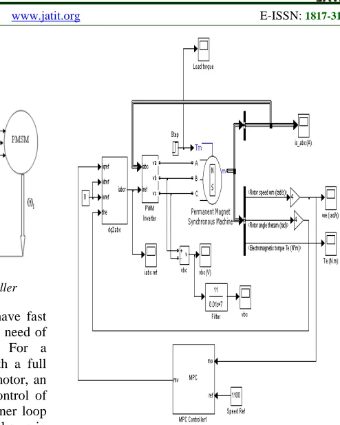
Figure 3 Simulation Diagram Of Proposed System
7. RESULTS AND DISCUSSIONS
Simulation results show that the MPC controller succeeded in well tracking given speed reference trajectories with less current and force ripples. Figure 4 and Figure 5 show the MATLab simulation diagram and output voltage of PWM inverter respectively.
[image:4.612.318.522.511.687.2]Figure 5 PWM Inverter Output Voltage (Phase – Phase)
Overshoot - Maximum
Figure 6 Speed Variation With Conventional Controller
Figure 6 and Figure 7 shows the speed response of PMSM motor based on conventional controller and proposed MPC controllers respectively for a reference speed of 800 rpm.
[image:5.612.89.324.64.442.2]Overshoot - Less
Figure 7 Speed Variation With Proposed Mpc Controller
It can be clearly shown that steady state tracking accuracy is high for proposed controller compared to conventional controller. Also time
[image:5.612.315.520.120.286.2]taken to reach its steady state reference value is very less in proposed MPC controller than conventional controller.
Figure 8 Motor Torque Curve (-3 Nm To 3 Nm)
[image:5.612.315.519.313.474.2]Figure 8 shows the motor electromagnetic torque for an applied torque of -3 Nm to 3 Nm.
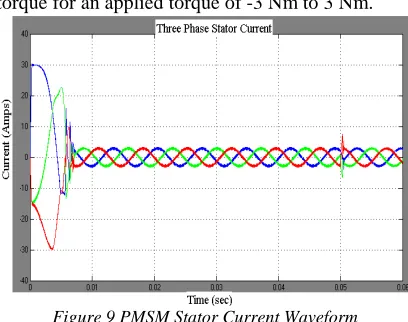
Figure 9 PMSM Stator Current Waveform
Figure 9 shows stator current response of the proposed MPC controller for PMSM when the load torque has step change from negative three to positive three Nm (-3 Nm to +3Nm) at 0.05s. The proposed control system has good dynamic performance.
7.1 SPECIFICATIONS OF PMSM
• Stator resistance: 2.875 ohm • Armature Inductance: 0.00153 H • Permanent magnet Flux: 0.175 • Pole Pair: 4
• Friction factor: 0.0003035 Nm-s • Moment of Inertia: 0.8e-3 Kg.m2 • Rated speed: 3750rpm
• Torque: 1.7 Nm
8. CONCLUSION
[image:5.612.92.493.509.686.2]speed and/or position of the Permanent Magnet Motor drive. It has been proved that the proposed controller has faster response than any traditional controller. Moreover, it shows more robustness against parameter uncertainty and load disturbance. The proposed MPC controller response has many advantages; very fast response, robustness against parameter uncertainties and load changes, well tracking of speed trajectory and has less current and force ripples. It has been shown that the MPC controller offers better response. Future work should include experimental works to validate this technique practically.
REFRENCES:
[1] A. G. Beccuti, S. Mariethoz, S. Cliquennois, S. Wang, and M. Morari, “Explicit model predictive control of dc–dc switched-mode power supplies with extended Kalman filtering,” IEEE Trans. Ind. Electron., vol. 56, no. 6, pp. 1864–1874, Jun. 2009.
[2] M. Cychowski, K. Szabat, and T. Orlowska-Kowalska, “Constrained model predictive control of the drive system with mechanical elasticity,” IEEE Trans. Ind. Electron., vol. 56, no. 6, pp. 1963–1973, Jun. 2009.
[3] S. Kouro, P. Cortes, R. Vargas, U. Ammann, and J. Rodriguez, “Model predictive control— A simple and powerful method to control power converters,” IEEE Trans. Ind. Electron., vol. 56, no. 6, pp. 1826–1838,Jun. 2009. [4] H. Miranda, P. Cortes, J. I. Yuz, and
J.Rodriguez, “Predictive torque control of induction machines based on state-space models,” IEEE Trans. Ind. Electron., vol. 56, no. 6, pp. 1916–1924, Jun. 2009.
[5] T. Geyer, G. Papafotiou, and M. Morari, “Model predictive direct torque control—Part I: Concept, algorithm, and analysis,” IEEE Trans. Ind. Electron., vol. 56, no. 6, pp. 1894– 1905, Jun. 2009.
[6] P. Cortes, J. Rodriguez, P. Antoniewicz, and M. Kazmierkowski, “Direct power control of an AFE using predictive control,” IEEE Trans. Power Electron., vol. 23, no. 5, pp. 2516– 2523, Sep. 2008.
[7] A.A. Hassan, J. Thomas, “Model Predictive Control of Linear Induction Motor Drive,” in proc. IFAC Seoul, Korea, July 6-11, 2008. [8] J. Rodriguez, J. Pontt, C. A. Silva, P. Correa, P.
Lezana, P. Cortes, and U. Ammann, “Predictive current control of a voltage source inverter,” IEEE Trans. Ind. Electron., vol. 54, no. 1, pp. 495–503, Feb. 2007.
[9] S. Muller, U. Ammann, and S. Rees, “New time-discrete modulation scheme for matrix converters,” IEEE Trans. Ind. Electron., vol. 52, no. 6, pp. 1607–1615, Dec. 2005.
[10] J. Rodrıguez, J. Pontt, C. Silva, P. Cortés, S. Rees, and U. Ammann,“Predictive direct torque control of an induction machine,” in Proc. PEPEMC, Riga, Latvia, Sep. 2–4, 2004. [11] J. Rodrıguez, J. Pontt, C. Silva, M. Salgado, S.
Rees, U. Ammann,P. Lezana, R. Huerta, and P. Cortés, “Predictive control of a three-phase inverter,” Electron. Lett., vol. 40, no. 9, pp. 561–562, Apr. 29, 2004.