RGB Object Restoration using Morphological and Gabor Wavelet
Classifiers
Er. Babneet Kaur Dhillon
1Er. Sarita Bajaj
2 1M. Tech. Scholar
2Guide
1,2
Department of Electronics & Communication Engineering
1,2
Doon Valley Institute of Engineering and Technology, Karnal, Haryana India
Abstract—Gabor features, a well-researched topic, widely used in image processing applications such as object and faces recognition, also pattern recognition applications such as fingerprint recognition, character recognition, and texture segmentation etc. Object recognition in the field of computer vision focuses on the task of identifying or locating a set of objects in an image or video sequence. This paper concentrates on various image processing techniques and operators such as image enhancement, image restoration, encoding and decoding techniques. The various applications of image processing techniques have also been studied. When image is transferred from source to the destination, it will take large amount of bandwidth. This bandwidth consumption has to be minimised. Our work proposes the algorithm that are used for better performance of parameters such as Absolute mean brightness error (AMBE), Peak signal to noise ratio (PSNR), Normalized absolute error (NAE), contrast improvement, image sharpening, edge detection, noise removal and data security issues. We also showed that our new approach has considerable advantages and is substantially superior to the existing traditional methods especially in the field of robustness and accuracy.
Key words: Image Enhancement, Image Restoration, Morphological Image Processing Gabor Wavelets (GWs)
I. INTRODUCTION
Image processing belongs to the field of signal processing in which input and output signals are both images. In computer vision society, the concept of feature is used to denote a piece of information which specifies quantifiable property of an image, and is computed such that it quantifies some significant characteristics of that image and is used for solving the computational task related to a certain application. More specifically, features can refer to specific structures in the image such as simple structures like points or edges or complex structures like objects. In addition, the computation efficiency is also an important factor for image feature extraction and description.
For mathematical analysis, an image may be defined as a two dimensional function f(x,y) where x and y are spatial (plane) coordinates, and the amplitude of f at any pair of coordinates (x, y) is called the intensity or gray level of the image at that point. When x, y, and the intensity values of f are all finite, discrete quantities, we call the image a digital image
Due to imperfections in the imaging and capturing process, however, the recorded image invariably represents a degraded version of the original scene. The undoing of these imperfections is crucial to many of the subsequent image processing tasks. There exists a wide range of different degradations that need to be taken into account, covering for instance noise, geometrical degradations (pincushion
distortion), illumination and color imperfections (under/over-exposure, saturation),and blur. This paper concentrates on various image processing techniques that are used to remove the noise and any kind of irregularities present in an image using the digital computer. The noise or irregularity may creep into the image either during its formation or during transformation etc.
For the purposes of image analysis and pattern recognition there is always a need to transform an image into another better represented form. During the past five decades image-processing techniques have been developed tremendously and mathematical morphology in particular has been continuously developing because it is receiving a great deal of attention because it provides a quantitative description of geometric structure and shape and also a mathematical description of algebra, topology, probability, and integral geometry. It is mathematical in the sense that the analysis is based on set theory, topology, lattice algebra, function, and so on. Image Processing systems are becoming popular due to easy availability of powerful personnel computers, large size memory devices, graphics software etc. The various Image Processing techniques are Image representation, Image preprocessing, Image enhancement, Image segmentation, Image compression, Image restoration etc.
A. Image Enhancement
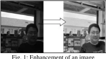
[image:1.595.343.513.591.685.2]Image enhancement plays an important role in the improvement of visual quality for computer vision, pattern recognition, and the processing of digital images. Several conditions may lead to poor contrast in digital images, including lack of operator expertise and inadequacy of the image capture device. Unfavorable environmental conditions in the captured scene such as the presence of clouds, lack of sunlight or indoor lighting, and so on, may also lead to reduced contrast quality. Essentially, if the overall luminance is insufficient, then the details of the image features will be obscured.
Fig. 1: Enhancement of an image
range of the chosen features so that they can be detected easily. The greatest difficulty in image enhancement is quantifying the criterion for enhancement and, therefore, a large number of image enhancement techniques are empirical and require interactive procedures to obtain satisfactory results.
Image enhancement methods can be based on either spatial or frequency domain techniques. Spatial domain technique enhances an image by directly dealing with the intensity value in an image. Transform domain enhancement techniques involve transforming the image intensity data into a specific domain by using methods such as DFT, DCT, etc. and the image is enhanced by altering the frequency content of the image.
Some useful methods of image enhancement are; Filtering with morphological operators, Histogram equalization, Noise removal using a Wiener filter, linear contrast adjustment, Median filtering, Unsharp mask filtering, Contrast-limited adaptive histogram equalization (CLAHE), Decorrelation stretch
B. Image Restoration
[image:2.595.46.288.421.533.2]Image restoration refers to removal or minimization of known degradations in an image. This includes deblurring of images degraded by the limitations of a sensor or its environment, noise filtering and correction of non-linearities due to sensors. Image restoration is a process that attempts to reconstruct and recover an image that has been degraded by using the phenomenon of degradation. In this technique an inverse process is used to restore the original image. This technique involves formulating certain criteria of goodness that gives the optimal estimate of the desired result.
Fig. 2: Damaged Image (2) Restored Image
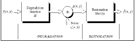
Restoration techniques may be formulated in the (a) Frequency domain (b) Spatial domain. The image restoration model is shown in below fig 1 where given g(x,y),some knowledge about H, and some knowledge about the noise term, the objective is to produce the estimate of the original image.
Fig. 3: Showing model of the image restoration process Now from the model given above if H is linear, position invariant process, then the degraded image can be described as the convolution of h and f with an added noise term-
g(x,y)=h(x,y)*f(x,y)+n(x,y)
Where h(x,y) is the spatial domain representation of the degradation function.
In the frequency domain,the representation is G(u,v)=H(u,v)F(u,v)+N(u,v)
Where each term in this expression is the Fourier transform of the corresponding terms in the equation above. Noise Models
1) Common sources of noise are,
Acquisition-which includes environmental conditions (heat, light), imaging sensor quality
Transmission-includes noise in transmission channel
2) Spatial and frequency properties of noise
Frequency properties of noise refer to the frequency content of noise in the Fourier sense.
For example-if the Fourier spectrum of the noise is constant, the noise is usually called the white noise
Expecting spatially periodic noise, we will assume that the noise is independent of spatial coordinates and uncorrelated to the image.
II. OVERVIEW OF OPERATORS
There are variety of operators that are used in image processing techniques such as morphological operator, power law trans-formation-technique, histogram-equalisation, gabor wavelet operator.
These operators are particularly useful for the analysis of binary images and common usages include edge detection, noise removal, image enhancement, image segmentation and encoding and decoding process. The following gives the overview about the operators.
A. Morphological Image Processing
The field of mathematical morphology contributes a wide range of operators to image processing, all based around a few simple mathematical concepts from set theory. Morphology is a broad set of image processing operations that process images based on shapes. Morphological operations apply a structuring element to an input image, creating an output image of the same size.
In a morphological operation, the value of each pixel in the output image is based on a comparison of the corresponding pixel in the input image with its neighbors. By choosing the size and shape of the neighborhood, you can construct a morphological operation that is sensitive to specific shapes in the input image.
The most basic morphological operations are dilation and erosion. Dilation adds pixels to the boundaries of objects in an image, while erosion removes pixels on object boundaries. The number of pixels added or removed from the objects in an image depends on the size and shape of the structuring element used to process the image. In the morphological dilation and erosion operations, the state of any given pixel in the output image is determined by applying a rule to the corresponding pixel and its neighbors in the input image. The rule used to process the pixels defines the operation as a dilation or an erosion. This table lists the rules for both dilation and erosion.
B. Rules for Dilation and Erosion
Operation Rule
Dilation
The value of the output pixel is the maximum
[image:2.595.50.284.604.676.2]the pixels is set to the value 1, the output pixel is set to 1.
Erosion
The value of the output pixel is the minimum
value of all the pixels in the input pixel's neighborhood. In a binary image, if any of the pixels is set to 0, the output pixel is set to
[image:3.595.43.289.53.145.2]0.
Table 1: Rules for Dilation and Erosion
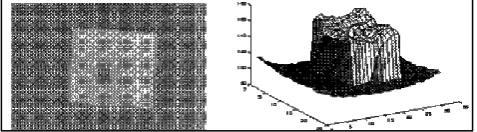
For a grayscale image, the intensity value is taken to represent height above a base plane, so that the grayscale image represents a surface in three-dimensional Euclidean space. Figure shows such a surface.
Fig. 2: Surface in three-dimensional Euclidean space
C. Gabor Wavelets (GWS)
Gabor wavelet had been used in past for object detection in Infrared Images, 3D object recognition and object tracking. The main aim to use GWs is due to their multi-resolution, multi-orientation properties. The use of Gabor wavelet approach has several advantages such as robustness against facial expression, illumination, image noise and invariance to some degree with respect to small changes in head pose, selectivity in scale, as well as selectivity in orientation.
Gabor Wavelets (GWs) with good characteristics of space-frequency localisation are used for extracting local features for various applications such as object detection, recognition and tracking, face tracking, optical character recognition, iris recognition, fingerprint recognition, and texture analysis. The Gabor wavelet representation of an image is the convolution of the image with a family of Gabor Wavelets. GWs use Gabor functions which was first proposed in 1946 by Dennis Gabor. Gabor transform is the short-time Fourier transform, used to determine the sinusoidal frequency and phase content of a signal which changes with time. A complex Gabor filter is defined as the product of a Gaussian kernel times a complex sinusoid which is then transformed with a Fourier transform to derive the time-frequency analysis. The Gabor transform of a signal x(t) is defined by this formula
𝐺𝑥(𝑡, 𝑓) = ∫ 𝑒−𝜋(𝑇−𝑡)
2
𝑒−𝑗2𝜋𝑓𝑇𝑥(𝑇)𝑑𝑇 ∞
−∞
The Gabor representation was first introduced for the 1-D then extending the representation to 2-D by Ebrahimi, et al show usefulness in image sequence coding where high compression ratios and modest image quality are required.
III. LITERATURE REVIEW
Sunita Dhariwal et al. [1] proposed some techniques in the area of image enhancement for brightness preservation as brightness preservation is in great demand in the consumer electronics field, when the image is effectively enhanced. The best results had been given in order to illustrate the best possible technique that can be used as powerful image enhancement. The performance of several established image enhancement techniques were presented in terms of different parameters like Absolute mean brightness error (AMBE),
Peak signal to noise ratio (PSNR), Normalized absolute error (NAE), contrast, correlation and visual quality to make real-time image-processing applications more feasible and easier In this paper, a frame work for image enhancement based on prior knowledge on the Histogram Equalization had been presented. Many image enhancement schemes like Contrast limited Adaptive Histogram Equalization (CLAHE), Equal area dualistic sub-image histogram equalization (DSIHE), Dynamic Histogram equalization (DHE) algorithms had been implemented and compared. From the experimental results, it is found that all the three techniques yields different aspects for different parameters.
Enming Luo,Stanley H.Chan,Truong Q Nguyen et al. [2] proposed an adaptive learning procedure to learn patch-based image priors for image denoising. They proposed a new algorithm, called the expectation-maximization (EM) adaptation, derived from a Bayesian hyper-prior perspective. takes a generic prior learned from a generic external database and adapts it to the noisy image to generate a specific prior.Different from existing methods that combine internal and external statistics in ad hocways, the proposed There are two contributions of this paper. Firstly,they gave full derivation of the EM adaptation algorithm and demonstrate methods to improve the computational complexity. Second, in the absence of the latent clean image, they showed how EM adaptation can be modified based on pre-filtering. The experimental results showed that the proposed adaptation algorithm yields consistently better denoising results than the one without adaptation and is superior to several state-of-the-art algorithms and the results demonstrated its superiority over some existing denoising algorithms, such as EPLL and BM3D.
Manjit Sandhu, Jaipreet kaur, Sukhdeep Kaur et al. [3] proposed a new technique for the data security issues while sending the data over the network using steganographic techniques. They gave an overview about encoding the image using Steganography which is art and science of writing hidden messages in such a way that no one apart from the sender and the intended recipient can realize that hidden data. Firstly the binary representations of hidden data are taken and then overwrite the LSB of each byte within the cover image and get the encoded image i.e. cover image with message image. Then from histogram of cover, message and encoded images respectively difference between original cover and encoded image is made clear. At the last extraction of message image from encoded image is done by shifting the bits in opposite direction. They showed that steganography is simplest method which provide privacy and secrecy both in case of hiding image within image. Steganography applies not only to digital images but to other media as well, such as audio files, communication channels, and other text and binary files.
[image:3.595.48.287.195.261.2]original features, which are considered as the characters of the image.
Bh. P., et al. [5]. Proposed the Elliptic Curve Cryptography. In this method encoding and decoding a text in the implementation of Elliptic Curve Cryptography is a public key cryptography using Koblitz's method. In their work, each point on the curve represents one character in the text message. When the message is passed each character is encoded by its ASCII code then the ASCII value is encoded to one point on the curve and so on. Our work differs from their work. In their work they used public-key technique whereas in our work we use private key technique. They encoded each character by its ASCII value but we encode each character by one pixel (three integer values - R for Red, G for Green and B for Blue).
IV. EXPERIMENTAL RESULTS
We have taken a particular image for applying the respective filters. All the filters are applied on this image Following figures show the respective operations.
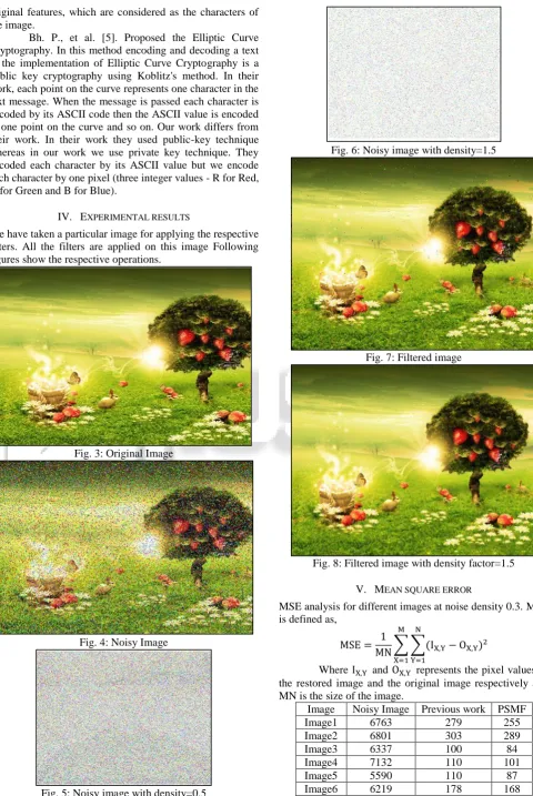
[image:4.595.55.536.49.767.2]Fig. 3: Original Image
Fig. 4: Noisy Image
Fig. 5: Noisy image with density=0.5
Fig. 6: Noisy image with density=1.5
Fig. 7: Filtered image
Fig. 8: Filtered image with density factor=1.5
V. MEAN SQUARE ERROR
MSE analysis for different images at noise density 0.3. MSE is defined as,
MSE = 1
MN∑ ∑(IX,Y− OX,Y
N
Y=1 M
X=1
)2
Where IX,Y and OX,Y represents the pixel values of
the restored image and the original image respectively and MN is the size of the image.
Image Noisy Image Previous work PSMF
Image1 6763 279 255
Image2 6801 303 289
Image3 6337 100 84
Image4 7132 110 101
Image5 5590 110 87
[image:4.595.322.539.682.768.2]Image7 6649 174 161
Image8 6417 341 303
Image9 6376 331 277
Image10 6402 140 134
Table 2: MSE analysis
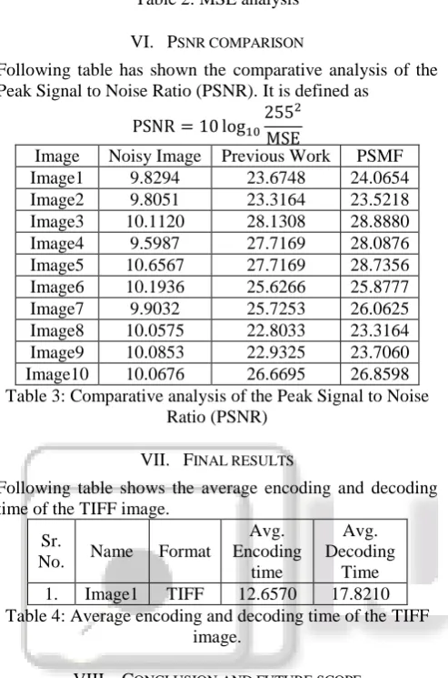
VI. PSNR COMPARISON
Following table has shown the comparative analysis of the Peak Signal to Noise Ratio (PSNR). It is defined as
PSNR = 10 log10
2552
MSE
Image Noisy Image Previous Work PSMF
Image1 9.8294 23.6748 24.0654
Image2 9.8051 23.3164 23.5218
Image3 10.1120 28.1308 28.8880
Image4 9.5987 27.7169 28.0876
Image5 10.6567 27.7169 28.7356
Image6 10.1936 25.6266 25.8777
Image7 9.9032 25.7253 26.0625
Image8 10.0575 22.8033 23.3164
Image9 10.0853 22.9325 23.7060
[image:5.595.57.276.54.130.2]Image10 10.0676 26.6695 26.8598
Table 3: Comparative analysis of the Peak Signal to Noise Ratio (PSNR)
VII. FINAL RESULTS
Following table shows the average encoding and decoding time of the TIFF image.
Sr.
No. Name Format
Avg. Encoding
time
Avg. Decoding
Time
[image:5.595.47.294.109.482.2]1. Image1 TIFF 12.6570 17.8210
Table 4: Average encoding and decoding time of the TIFF image.
VIII. CONCLUSION AND FUTURE SCOPE
The main focus of this research is on encoding and decoding of an image. The proposed work also focuses on enhancement of images using various image enhancement techniques. Experiment was done on poor quality image initially and is compared to result proposed method and previous method. In recent years, many researchers have applied the fuzzy logic to develop image processing algorithms. We have used various filtering methods to filter out the noise and to enhance the image quality. The proposed algorithm is tested on different type of images. The experimental result shows that the brightness is increased as compared to previous one. In our work we have shown encoding and decoding time of different images and compare them. The proposed work gives a better solution in terms of decoding of images as the obtained decoding time comes out to be approximately same for all kind of images which shows the efficiency of the algorithm.
Future work can be extended for other images then grayscale images to obtain better result with accuracy. In future modification of the algorithm can produce the better result for the image. This study will provide guidelines to the researchers working in this area.
REFERENCES
[1] Enming Luo,Stanley H.Chan,Truong Q Nguyen, “Adaptive Image Denoising by Mixture Adaptation”, IEEE Trans. Image Processing, Vol. 25, no. 10, Oct. 2016.
[2] Manjit Sandhu, Jaipreet Kaur, Sukhdeep Kaur “Encoding and Decoding of Image using Steganography Technique”, International Journal of Advanced Research in Electronics and Communication Engineering (IJARECE) Volume 5, Issue 6, June 2016.
[3] Xing Wu and Bir Bhanu, Fellow, IEEE, “Gabor Wavelet Representation for 3-D Object Recognition”, IEEE Transactions on Image Processing, vol. 6, no. 1, January 2015.
[4] Rolf P. Würtz, “Object Recognition Robust under Translations, Deformations, and Changes in Background”, IEEE Trans on Pattern Analysis and Machine Intelligence, pp. 769–799, July 2014.
[5] Ayushi Jaiswal 1, J.P. Upadhyay 2, Ravi Mohan S.3,P. Bohre4 “A Novel Approach for Reduction of Poisson Noise in Digital Images” A. Jaiswal et al Int. Journal of Engineering Research and Applications www.ijera.com ISSN: 2248-9622, Vol. 3, Issue 5, Sep-Oct 2013, pp. 1275-1279.
[6] Rani, Versha. "A Brief Study of Various Noise Model and Filtering Techniques "Journal of Global Research in Computer Science 4, no. 4 (2013): 166-171.
[7] Singh, Shiv, and Dr GC Lall. "Performance Analysis of Various Impulse Noise Reduction Techniques in Images." International Journal of Advanced Research in Computer Science and Software Engineering 2, no. 6 (2012).
[8] Singhal, Arpit, and Mandeep Singh. "Speckle Noise Removal and Edge Detection using Mathematical Morphology." International Journal of Soft Computing and Engineering (IJSC (, ISSN: 2231-2307, Vol. 1, Issue 5 (2011).
[9] Sunita Dhariwal, “Comparative Analysis of Various Image Enhancement Techniques”, International Journal of Electronics & Communication Technology (IJECT), Vol. 2, Issue 3, pp. 91-95, Sept. 2011.
[10]Y. Wang, Q. Chen, B. Zhang, “Image enhancement based on equal area dualistic sub-image histogram equalization method,” IEEE Trans. on Consumer Electronics, vol. 45, no. 1, pp. 68-75, Feb. 2010. [11]Juneja, Mamta, and Rajni Mohana. "An improved
adaptive median filtering method for impulse noise detection." International Journal of Recent Trends in Engineering 1, no.1 (2009): 274-278