2019 International Conference on Computer Science, Communications and Big Data (CSCBD 2019) ISBN: 978-1-60595-626-8
Design and Implementation of Mesh-based Multimedia Transmission
System at 400MHz
Chang-bing XIAO
*Master's Degree, Beijing University of Posts and Telecommunications, China
*Corresponding author
Keywords: 400MHz, Mesh, Multimedia Transmission System.
Abstract. In order to solve fast networking in a complex environment and high quality transmission
of video and audio signals emergency communication problem. A multimedia transmission system based on Mesh self-organizing network at 400MHz is proposed. Firstly, the advantages of the system compared with the existing multimedia transmission system in the 2.4GHz band are described. Then the 400MHz Mesh self-organizing network multimedia transmission system is described. Design principle and hardware and software composition, and finally test the actual application effect of the designed system. The test results show that the system can realize multi-node rapid networking in complex environments and achieve higher quality multimedia data transmission functions, which can be promoted in the field of emergency communication and video surveillance.
Introduction
With the advancement of society and the development of science and technology, multimedia information transmission plays an increasingly important role in our life. The traditional multimedia transmission system is mainly connected by cables, and the transmission is stable, but the installation and wiring are complicated, the lines are easily damaged, and it is difficult to move. These shortcomings seriously restrict the development of the multimedia transmission system. Existing wireless transmission systems mainly include mobile communication networks and wireless local area networks (WLANs).
The mobile communication network has the advantages of wide coverage, high transmission rate and small transmission delay [1]. However, due to the large amount of data transmitted by multimedia and the high transaction cost of the mobile communication network, multimedia transmission based on the mobile communication network is not economical. In addition, in many occasions where large power base stations or base stations cannot be built, such as earthquake relief sites, various mines, and various military security occasions, mobile communication networks are difficult to set up quickly. WLAN is a popular wireless network. However, a WLAN must have a core node as an access point (AP) of the network. Other terminals must be directly connected to the AP. Once the access point AP fails or is damaged, the connected terminal loses communication ability [2].
Overall Design of Multimedia Transmission System
[image:2.595.199.393.295.368.2]Wireless Mesh Networks (WMNs) are data networks with mesh topology formed by nodes that establish and maintain the network connectivity automatically [4]. The wireless Mesh network is a dynamic self-organizing, self-configuring network that can easily provide robust and reliable network coverage. The wireless Mesh network-based remote monitoring system can provide high-speed and high-flexibility wireless access by constructing a self-organized wireless Mesh network to transmit high-definition video images. Widely used in many fields such as intelligent transportation, public safety, industrial monitoring, etc. Using the 400MHz band is more suitable for networking in particularly complex environments. Fig. 1 is a schematic diagram of a multimedia transmission system networking. The multimedia transmission system based on Mesh network needs to collect multimedia information and wirelessly transmit multimedia information in real time. There are two types of nodes designed. As shown in Fig. 1, there are five common Mesh nodes and one central Mesh node. Each node transmits the collected data by wireless means to the other nodes in the vicinity and then other nodes continue to carry out the multi-hop transmission until the data reach the central Mesh node [5].
Figure 1. The schematic diagram of a multimedia transmission system networking.
Mesh Network Node Structure
The common Mesh node, the schematic diagram is shown in Fig. 2. The multimedia information is collected by the camera device and the microphone device, and the multimedia processing module compresses and encodes the collected video and audio data, and the compressed and encoded data information is converted into a radio frequency signal by the signal transceiving module, and is transmitted through the antenna. Taking into account the portable requirements of the device, the battery is used to power each module, so that the movement of the node becomes very convenient.
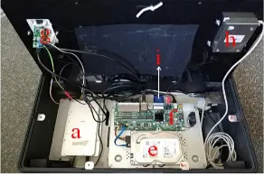
The central Mesh node, the schematic diagram is shown in Fig. 3. Because the meshing mode of the Mesh network is adopted, in theory, the status of each node in the network is equal, and any node can be used as a central Mesh node or a common node, but considering the actual situation, only one of the nodes is selected as the center Mesh node. The difference between the central Mesh node and the common Mesh node structure is mainly increased, and devices such as a display and a hard disk recorder are added. The central Mesh node receives the multimedia data transmitted by other Mesh nodes through the signal transceiver module, and the data is transmitted to the hard disk recorder and stored in the hard disk, and the received picture is displayed on the display, and if it is voice data, it is transmitted from the earphone.
Figure 2. The schematic diagram of a common Mesh node. Figure 3. The schematic diagram of a central Mesh node.
System Hardware Device Selection
[image:2.595.80.524.627.712.2]hard disk, monitor, mouse, battery and various materials. Table 1 shows the corresponding channels, channel bandwidth and occupied frequency of the wireless signal transceiver module.
Table 1. Channel, channel bandwidth and occupancy frequency.
Channel bandwidth Shrine ID Center frequency Occupancy frequency
5MHz
1 395MHz 392.5-397.5MHz
2 400MHz 397.5-402.5MHz
3 405MHz 402.5-407.5MHz
10MHz
1 395MHz 390-400MHz
2 400MHz 395-405MHz
3 405MHz 400-410MHz
20MHz 2 400MHz 390-410MHz
Multimedia Transmission System
OpenWrt
OpenWrt is a highly extensible GNU/Linux distribution for embedded devices (typically wireless routers) [6]. OpenWrt system as a highly modular, highly automated embedded Linux system. It is a full-featured, easy-to-modify router operating system written from scratch. The system is more flexible and stable, with powerful network components and scalability. The system has built-in package management tools, you can install software directly from a software repository.
So here this study chose to use the OpenWrt operating system and load it into the wireless signal transceiver module. First, use the VMware virtual machine to build the compilation environment. According to the core chip parameters of ERS400 (AR9344 produced by Qualcomm), configure the compile option through the make menuconfig command to enable it to support the wireless transceiver module. After the compilation is completed, the firmware of the compiled adaptive wireless signal transceiver module can be programmed into the wireless signal transceiver module through the UART interface, and finally the module is restarted.
Node Assembly And Device Connection
For common Mesh nodes, each module is first placed on a cut hard plastic plate of about 3 mm thickness, and then the plastic plate is fixed in the carrying case. The wireless signal transceiver module and camera are powered using a rechargeable battery. For the central Mesh node, because the DVR, hard disk, display, mouse and other devices are installed, it consumes more power, and uses power cord to power it. Fig. 4 and Fig. 5 show the physical map of the common Mesh node and the physical map of the central Mesh node.
In Fig. 4, the battery c supplies power to the wireless signal transceiver module a and the camera
b at the same time, and the multimedia data collected by the camera b is transmitted to the a through the network cable, and is transmitted through the antenna d. In Fig. 5, the information received by the wireless signal transceiver module through the antenna is transmitted to the DVR f, and f
processes the received data and stores it in the large capacity hard disk e. g is the headset interface and network port connected to the DVR, i is the VGA video cable, and h is the mouse.
[image:3.595.329.475.647.745.2][image:3.595.119.276.648.745.2]
System Networking and Application
System Network Test
[image:4.595.207.388.182.287.2]The system is based on a wireless Mesh network, and the ERS400 wireless signal transceiver module operates in the 400 MHz band. Set the IP of the wireless signal transceiver module and the network camera on the same network segment to connect them. Configure the transmit power, signal bandwidth, channel and other parameters of the wireless signal transceiver module, and set the appropriate parameters for the network camera.
Figure 6. The transmission effect diagram of the video after successful networking.
Table 2. Main parameters seting.
Transmit power bandwidth Shrine ID Video bit rate Frame rate Resolution
Networking test 30dBm 10MHz 2 2Mbps 25 1280*720
Environmental test 30dBm 5MHz 2 1Mbps 25 640*480
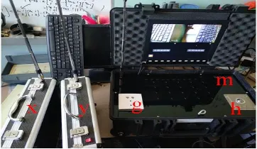
The main parameters of the network test settings are shown in Table 2. After the device is powered on, the two common Mesh nodes are successfully connected to the central Mesh node and implement video transmission. Fig. 6 is a transmission effect diagram of the video after successful networking. It can be seen that the video screen acquired by the common Mesh node x and the common Mesh node y is received on the display of the center Mesh node m.
Actual Environmental Test
Select 4 Mesh nodes, where m is a central Mesh node, x, y, and z are 3 common Mesh nodes for actual environment test. The main parameters of the actual environmental test settings are shown in Table 2. Place 4 Mesh nodes in different locations on the same floor of the complex office building. The connection diagram and measured results are shown in Fig. 7.The four Mesh nodes are placed in different layers of the complex office building. The connection diagram and test results are shown in Fig. 8.
[image:4.595.84.515.559.666.2]
Figure 7. The same floor. Figure 8. The different floor.
Conclusion
implement most of the existing multimedia transmission functions. The system's fast networking and multi-hop transmission advantages make it particularly suitable for use as an emergency communication system in emergency situations.
References
[1] Raychaudhuri D, Mandayam N B. Frontiers of Wireless and Mobile Communications, J. Proceedings of the IEEE, 2012, 100(4):824-840.
[2] Rappaport, Theodore. Wireless Communications: Principles and Practice, J. 2002. [3] Zhong Hui, Zhang Bo, and Cheng Jiwei, Implementation of Wireless Mesh Network Protocol Research Platform, in Proc. International Conference on Communications and Mobile Computing (CMC), 2010, vol. 3, pp. 509-511, April 2010.
[4] Armuelles-Voinov I, Chung-Miranda J, Chung-Cedeno A. Evaluation of QoS provisioning in nodes of Wireless Mesh Networks based on IEEE 802.11s, C//Central America & Panama Convention. IEEE, 2015.
[5] Liu Wei, Wu Yuhong, The Study of Routing Protocol in Wireless Mesh Network, Xidian University, pp. 27-30, 2006, 12.