Heuristic Synthesis of Reversible
Logic – A Comparative Study
Chua Shin CHENG
1, Ashutosh Kumar SINGH
21Department of Electrical and Computer Engineering, Curtin University,
Sarawak, CDT 250, Miri 98009, Malaysia
2Department of Computer Application, National Institute of Technology,
Kurukshetra-136119, Haryana, India
[email protected], [email protected]
Abstract. Reversible logic circuits have been histor-ically motivated by theoretical research in low-power, and recently attracted interest as components of the quantum algorithm, optical computing and nanotech-nology. However due to the intrinsic property of re-versible logic, traditional irrere-versible logic design and synthesis methods cannot be carried out. Thus a new set of algorithms are developed correctly to synthe-size reversible logic circuit. This paper presents a comprehensive literature review with comparative study on heuristic based reversible logic synthesis. It re-views a range of heuristic based reversible logic syn-thesis techniques reported by researchers (BDD-based, cycle-based, search-based, non-search-based, rule-based, transformation-based, and ESOP-based). All tech-niques are described in detail and summarized in a ta-ble based on their features, limitation, library used and their consideration metric. Benchmark comparison of gate count and quantum cost are analysed for each syn-thesis technique. Comparing the synsyn-thesis algorithm outputs over the years, it can be observed that different approach has been used for the synthesis of reversible circuit. However, the improvements are not significant. Quantum cost and gate count has improved over the years, but arguments and debates are still on certain issues such as the issue of garbage outputs that remain the same. This paper provides the information of all heuristic based synthesis of reversible logic method pro-posed over the years. All techniques are explained in detail and thus informative for new reversible logic re-searchers and bridging the knowledge gap in this area.
Keywords
Ancilla input, garbage output, heuristic, quan-tum cost, reversible logic, synthesis.
1.
Introduction
Landauer, has shown that when an irreversible com-putational system perform any logic operation, a bit of information is erased [1], each of this information erased is converted tokTIn2 Joule of heat, wherek is Boltzmann constant which is1.38065·10−23J/K andT is the environment temperature [2]. Today, all comput-ers erase bit of information every time a logic operation is performed due to the irreversible computational sys-tem used. As Moore’s Law continues to hold, whereby the number of transistor in an integrated circuit dou-bles every 18 months [3], with the current irreversible technologies, that heat generated by each IC also dou-bles accordingly [4]. If this situation proceeds, Moore’s Law will not remain valid after year 2020 as the amount of heat generated by the large number of transistors in an IC had reached a limit that the IC can bear and unable to go further.
An alternative way to overcome this problem is to use logic operations that do not erase information [5]. These types of logic operations are called reversible logic operations. Bennett [6] has proved that informa-tion lost would not occur if a computainforma-tion is carried in a reversible way, since the amount of energy dissipated in a system bears a direct relationship to the number of bits erased during computation.
Reversible gates are logic gates that use reversible logic operation, its operation do not erase information and dissipate very less heat. Nowadays, research in reversible logic has received considerable attention in various areas such as low-power computing devices, op-tical computing [7], quantum computing [8] and nan-otechnology [9].
The synthesis of reversible logic differs significantly from traditional irreversible logic synthesis due to the difference in their characteristic. A reversible gate is a logical cell that has the same amount of inputs and
out-puts which has a bijective mapping between the input and output vectors. Direct fan-outs from a gate output to multiple gates and input as well as feedbacks from a gate output directly to its inputs are not allowed [10]. Due to such unique features of reversible circuits, ex-isting algorithms and tools for circuit synthesis and op-timization using irreversible logic gates cannot be used for reversible logic [11]. Therefore new methods are developed to synthesize and optimize reversible logic.
In this survey paper, we focused on heuristic based synthesis algorithm of reversible logic which includes most of the well-known algorithms proposed by differ-ent authors over the years.
2.
Reversible Logic
Preliminaries
2.1.
Reversible Function
A logic functionf(x1, x2, ..., xn)of n Boolean variables is reversible if it maps each input assignment to an unique output assignment.
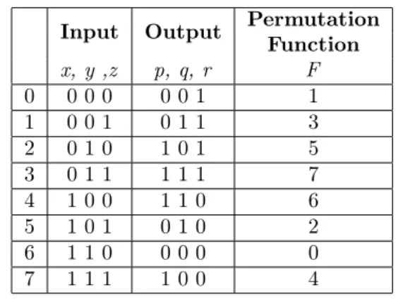
Example: Table 1 illustrates a reversible function of three variables. The functionf = (1,3,5,7,6,2,0,4)
is permuted over(0,1,2,3,4,5,6,7)where there exist a one-to-one relationship off(0) = 1,f(1) = 3,f(2) = 5,
f(3) = 7,f(4) = 6,f(5) = 2,f(6) = 0,f(7) = 4. Each output is assigned to a unique input with no repeating.
Tab. 1: Reversible function.
Input Output Permutation Function x, y ,z p, q, r F 0 0 0 0 0 0 1 1 1 0 0 1 0 1 1 3 2 0 1 0 1 0 1 5 3 0 1 1 1 1 1 7 4 1 0 0 1 1 0 6 5 1 0 1 0 1 0 2 6 1 1 0 0 0 0 0 7 1 1 1 1 0 0 4 1) Cycles
A cycle of lengthkwhich represented by disjoint cycles of variables is denoted by(x1, x2, ..., xk)wheref(x1) =
x2, f(x2) = x3, ..., f(xk) = x1. This representation is necessary for reversible logic because it is based on permutation which is a bijective function. The length of a cycle is the number of elements it contains [12]. A cycle with length two is called a transposition. When two cycles c1 and c2 are disjoint they can commute,
i.e. c1c2 = c2c1. Other than that, a cycle may be
written in different ways as a product of transpositions and using different numbers of transpositions. Cycles can be categorized as even and odd with respect to the number of permutations [13].
Example: The truth table in Tab. 2 can be repre-sented by(2,3) (6,7) because the corresponding func-tion swaps010and011; and 110to111.
Tab. 2: Reversible function and its permutation function.
Input Output Permutation Function x, y ,z p, q, r F 0 0 0 0 0 0 0 0 1 0 0 1 0 0 1 1 2 0 1 0 0 1 1 3 3 0 1 1 0 1 0 2 4 1 0 0 1 0 0 4 5 1 0 1 1 0 1 5 6 1 1 0 1 1 1 7 7 1 1 1 1 1 0 6
2.2.
Reversible Gates
A reversible gate realizes a reversible function. If a re-versible gate has k input and output wires, it is called as ak×k gate, or a gate on k wires [14]. Reversible gates have the same number of input and output i.e. one-to-one mapping between these two vectors. There-fore the input states can be always reconstructed from the output states. The commonly used reversible gates are illustrated below.
1) Multiple-Control Toffoli Gate
A multi-control Toffoli gate [15], [16] can be written as CnNOT(x
1, x2, ..., xn+1)on TOF(x1, x2, ..., xn, xn+1).
The gate maps a Boolean pattern (x1, x2, ..., xn+1)
to(x1, x2, ..., xn;x1x2...xn⊕xn+1)for case n≥2. For n= 1, it maps a Boolean pattern of (x1)to( ¯x1). For n = 0,1,2 the gate are called as NOT, CNOT and Toffoli (CnNOT) gate. These three gates compose the universal NCT library. The general structure of NOT, CNOT and Toffoli gate is illustrated in Fig. 1.
(a) (b)
2) Multi-Control Fredkin Gate
A multi-control Fredkin gate [17] can be writ-ten as (x1, x2, ..., xn, xn+1, xn+2). The gate maps
a Boolean pattern (x1, x2, ..., xn, xn+1, xn+2) to
(x1, x2, ..., xn, xn+2, xn+1) if and only the Boolean
product x1, x2, ..., xn = 1, otherwise the input will not be swapped. For n = 0,1,2 the gate are called SWAP and Fredkin gate. By adding these two gates to the NCT library, they form the NCTSF library. The general structure of SWAP and Fredkin gate is illustrated in Fig. 2.
(a) (b)
Fig. 2: (a) SWAP gate (b) Fredkin gate.
3) Peres Gate
Peres gate [18] has only three inputs and outputs. The gate maps a Boolean pattern (x1, x2, x3) to (x1, x2⊕ x2, x1, x2⊕x3). The general structure of Peres gate is
illustrated in Fig. 3(a).
(a) (b)
Fig. 3: (a) Peres gate (b) Inverse Peres gate.
4) Inverse Peres Gate
The inverse Peres gate is also known as the TF gate in [19]. The gate is the inverse connection of the Peres gate where we treat it outputs as inputs and inputs as outputs. The gate maps a Boolean pattern(x1, x2, x3)
to(x1, x1⊕x2, x1⊕x3⊕x1x2). The general structure
of inverse Peres gate is illustrated in Fig. 3(b).
2.3.
Elementary Quantum Gate
All reversible gates greater than 2 bits are realized with a combination of several elementary quantum gates [20]. The widely used elementary gates are the NOT, the CNOT, the controlled - V and controlled - V+ [16]. Unlike normal logic gates operation, elementary quan-tum gates manipulate with qubits rather than bits. In
a bit, there are two states which are either 0 or 1, whereas for qubit, the two states are|0iand|1i, where notation ‘|i’ is called the Dirac notation [21]. The dif-ference between bits and qubits is that the qubit can be in the state other than|0ior |1i. It is also possible to form alinear combinations of|ψi=α|0i+β|1i of-ten called assuperposition, whereαandβare complex numbers such that|α|2+|β|2= 1.
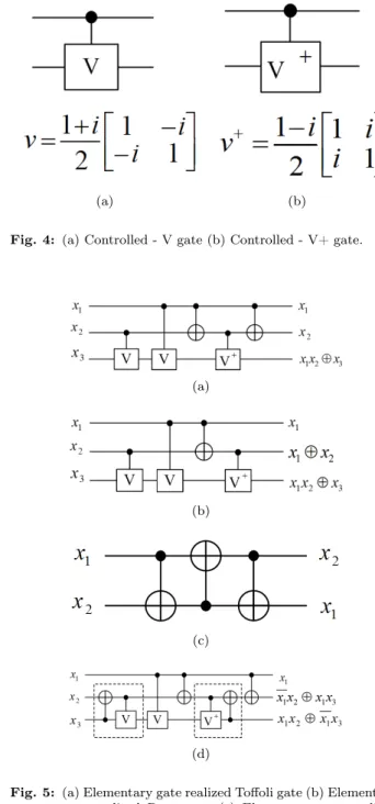
The diagram of controlled - V and controlled - V+ gates and operation are illustrated in Fig. 4. The ele-mentary quantum gate constructing the Toffoli, Peres, SWAP and Fredkin gate are illustrated in Fig. 5.
(a) (b)
Fig. 4: (a) Controlled - V gate (b) Controlled - V+ gate.
(a)
(b)
(c)
(d)
Fig. 5: (a) Elementary gate realized Toffoli gate (b) Elementary gate realized Peres gate (c) Elementary gate realized SWAP gate (d) Elementary gate realized Fredkin gate.
2.4.
Quantum Cost
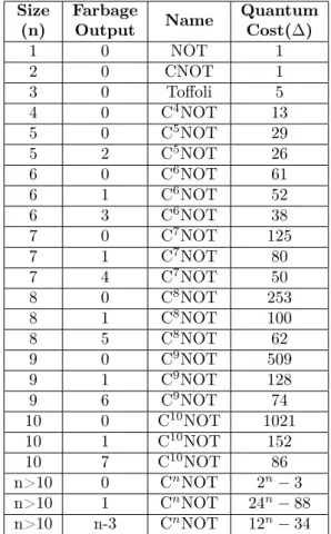
Tab. 3: Toffoli gate costs.
Size Farbage Name Quantum (n) Output Cost(∆) 1 0 NOT 1 2 0 CNOT 1 3 0 Toffoli 5 4 0 C4NOT 13 5 0 C5NOT 29 5 2 C5NOT 26 6 0 C6NOT 61 6 1 C6NOT 52 6 3 C6NOT 38 7 0 C7NOT 125 7 1 C7NOT 80 7 4 C7NOT 50 8 0 C8NOT 253 8 1 C8NOT 100 8 5 C8NOT 62 9 0 C9NOT 509 9 1 C9NOT 128 9 6 C9NOT 74 10 0 C10NOT 1021 10 1 C10NOT 152 10 7 C10NOT 86 n>10 0 CnNOT 2n−3 n>10 1 CnNOT 24n−88 n>10 n-3 CnNOT 12n−34
All reversible gates are associated with a cost called quantum cost. Quantum cost denotes the effort re-quired to transform a reversible circuit into a quantum circuit. Quantum cost is measured based on the num-ber of elementary quantum gate realized in the gate [22]. Each elementary gate contributes a quantum cost of ∆1. In Fig. 5(a), Toffoli gate have five elemen-tary quantum gates, so its quantum cost is ∆5. In Fig. 5(d), Fredkin gate has seven elementary quantum gates, however it only has a quantum cost is∆5, this is because two elementary quantum gates which shares the same line (quantum gates bracketed in the box) is consider as one. Quantum cost for SWAP, Peres and inverse Peres gate are∆3,∆4and∆4. Quantum cost of generalized Toffoli gates can be found in Tab. 3 [23]. For n≥ 3 size Fredkin gate, the quantum cost is the same as the Toffoli gate.
2.5.
Reversible Circuits
Reversible circuits are logic circuit constructed using only a combinational of reversible logic gates. In a re-versible circuit connection, direct fan-outs from a gate output to multiple gates and input as well as feedbacks
from a gate output directly to its inputs are not allowed [8], [10].
2.6.
Garbage Output
The unused output of a reversible circuit which does not perform any operation is called the garbage out-put. These outputs are required to maintain the cir-cuit in reversible to have an equal number of inputs and outputs [24]. Figure 6 shows an example of reversible function off =x1x2⊕x3, the two unused pins are the garbage outputs.
Fig. 6: Garbage output.
2.7.
Ancilla Input
The constant value input to a reversible circuit is called the ancilla input. In reversible circuit design, a reversible circuit with less ancilla input is preferred. However, some reversible function cannot be generated without using ancilla inputs i.e. a reversible AND gate required one ancilla as shown in Fig. 7(a). An ancilla input is added to a CNOT gate to act as a copying gate to explicit fan-out as shown in Fig. 7(b).
(a) (b)
Fig. 7: (a) Reversible AND gate (b) CNOT gate as copying gate.
2.8.
Representation Model
Reversible functions can be described in several ways as below:
1) Truth Table
Truth table is a straightforward representation to rep-resent a Boolean function but become cumbersome for a large number of variables [25]. A reversible function ofn variable can be represented in a column wide ofn
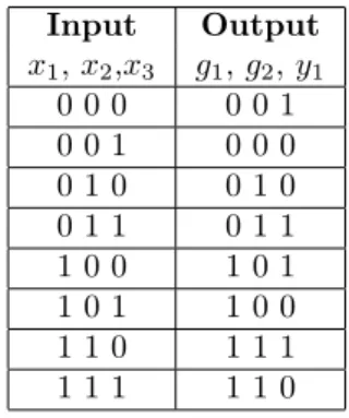
and a row of2n. Figure 8 and Tab. 4 shows an example of a reversible circuit and its truth table representation.
Fig. 8: Reversible circuit.
Tab. 4: Truth table representation.
Input Output x1,x2,x3 g1,g2,y1 0 0 0 0 0 1 0 0 1 0 0 0 0 1 0 0 1 0 0 1 1 0 1 1 1 0 0 1 0 1 1 0 1 1 0 0 1 1 0 1 1 1 1 1 1 1 1 0 2) Matrix
Matrix based representation can better reflects the quantum state evolution and the properties of quan-tum computation however it become cumbersome for reversible function with a large number of variable. It represents the permutation function of a reversible function in a 0-1 matrix with only one 1 appears in each column. Example below shows a matrix represen-tation of a CNOT gate with it truth table defined in Tab. 5.
Tab. 5: Truth table representation.
Input Output x,y p,q 0 0 0 0 0 1 0 1 0 1 2 1 0 1 1 3 1 1 1 0
The specific definition of CNOT assumes an eigen-basis of: |00i = 1 0 0 0 , |01i= 0 1 0 0 , |10i = 0 0 1 0 , |11i= 0 0 0 1 , (1)
writing all the output in column, we obtain:
CN OT = 1 0 0 0 0 1 0 0 0 0 1 0 0 0 0 1 . (2)
3) Binary Decision Diagram (BDD)
Any Boolean function can be graphically represented by different type of Decision Diagrams (DD) [26], [27]. A BDD is a directed acyclic graph where a Shannon decomposition(f = ¯x1fxi=0+ ¯xifxi=1)is carried out in
each non-terminal node. Generally BDD of a function may require a large amount of nodes which become impractical for function with large variables. Fig. 9 shows an example of a BDD.
Fig. 9: BDD forf=x2+x1x2.
4) Positive Polarity Reed-Muller (PPRM) Expansion
Any Boolean function can be described using an EXOR sum-of-product (ESOP) expansion [28]. The PPRM expansion only uses uncomplemented variables and it can be derived from the function’s sum-of-product (SOP) expression. To uncomplemented a comple-mented variable, this rules can be applied ¯a = 1⊕a. The PPRM expansion of a function is canonical and is defined as following: f(x1, x2, ..., xn =a0⊕a1x1⊕...⊕ a13x1x3⊕...⊕an−1,nxn−1xn⊕...⊕a12...nx1x2...xn). Whereai∈ {0,1}andxiare all uncomplemented (pos-itive polarity).
3.
Synthesis Algorithm
In this section, all heuristic based synthesis algorithms are described in the following subsections.
3.1.
BDD-Based Synthesis
Algorithm
Binary Decision Diagrams (BDDs) synthesis algorithm was first proposed by Kerntopf in [29]. The algorithm selects reversible gates, one at a time, based on the complexity of the reminder logic. In this method the Decision Diagrams are constructed for all the possible functions and minimal node BDD is selected. In [30], the algorithm synthesis a function starts by directly constructing a BDD. Then each node of the BDD is substituted by a cascade of reversible gates as seen in Fig. 10. As BDDs may contain shared nodes which result in fan-outs which are not allowed in reversible logic, therefore, additional circuit lines are needed to overcome this problem. The function being synthesis will result in a circuit composed of Toffoli or elemen-tary quantum gates respectively are obtained in linear time and with memory linear to the size of the BDD. The algorithm is able to synthesize large functions with more than a hundred of variable in low running-time. This algorithm leads to a good reduction in both quan-tum cost and run-time, but many constant and garbage lines are added which makes the results impractical.
In [31], a post-process optimization method is used to reduce the number of lines by merging some garbage output lines with appropriate constant input lines. Therefore, the resulting circuit generated by [30] can apply the algorithm in [31] to reduce the constant and garbage lines.
(a) (b)
Fig. 10: (a) BDD (b) Resulting circuit for a functionf=x1⊕
x2.
3.2.
Cycle-Based Synthesis
Algorithm
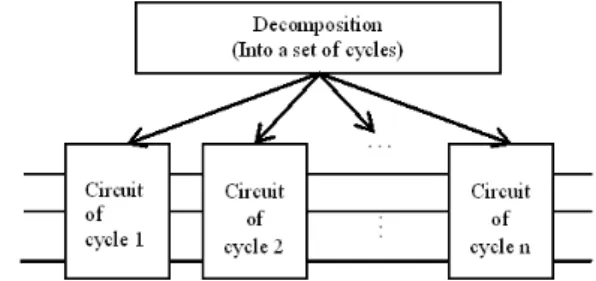
Cycle-based synthesis methods can be described as in Fig. 11. The method works by separating the entire permutation into a set of cycles and synthesize them separately. This divide and conquer method is effective against reversible functions that leave many inputs un-changed.
Fig. 11: A general outlines of cycle-based methods.
In [12], the authors proposed a synthesis method which can be implemented without temporary storage channels using the NCT library set. Each pair of dis-joint transpositions is implemented by a synthesis algo-rithm and the final circuit is constructed by cascading individual circuits.
In [32], an extension of the method from [12] is done which it reduces the unnecessary large number of cycle and synthesis cost by applying NOT and CNOT gate instead of Toffoli gate for many situations.
In [33], the synthesis algorithm decomposed a given large cycle into a set of single 3-cycles, pairs of 3-cycles and pair of 2-cycles and synthesize the resulted cycle directly.
However in [34], the authors develop ak-cycle-based synthesis method that uses a set of seven building blocks directly to synthesize a given permutation to reduce both quantum cost and average run-time. The seven building blocks includes a pair of 2-cycle, a sin-gle 3-cycle, a pair of 3-cycles, a sinsin-gle 5-cycle, a pair of 5-cycles, a single 2-cycle (4-cycle) followed by a sin-gle 4-cycle (2-cycle) and a pair of 5-cycles. In [35], a more efficient decomposition algorithm was proposed. The algorithm produces all minimal and in-equivalent factorizations each of which contains the maximum of disjoint cycles. Then a graph perfect matching algo-rithm is used to select the best possible matching pairs with the minimum cost.
In [36], the authors presented an implementation of an algorithm for finding optimal gate count of any 4-bit based reversible function. The algorithm is based on the set of all functions that have an optimal circuit up to 9 gates can be effectively stored in the computer nowadays. For each equivalent class of reversible func-tion the algorithm stores them only in their canonical form and thus reduces in the memory consumption. The reversible function database used in the algorithm is stored as hash tables. Using the database, the gate count of the optimal circuit can be easily found in a short amount of time through lookup in their canonical representative form. For synthesized reversible func-tion that requires more than 9 gate counts; an optimal circuit additional processing is used. The algorithm
will partitioned the function into two circuits such that
f =g◦r, wheref refers to the synthesized function,g and r refers to the two partitioned circuits and ◦ de-notes cascading of the circuits. By using the database, and partitioned synthesis, the algorithm archives great synthesis time.
In [37] the authors proposed a similar approach to [36] however their objective is to optimize in term of quantum cost with a given gate count. The authors have further extended their work in [38] which further improves the quantum cost result and able to optimize circuits of more than 4-bits.
In [39], an extension of the method from [36] is presented. The algorithm removes all inverse func-tions and added several new funcfunc-tions to the circuit databases. This improves the performance of the al-gorithm and allows to synthesize more 4-bit reversible functions.
In [40], the algorithm in [36] and [39] is extended which it combines the algorithm with depth-first search method for more effective pruning in the search tree. During the synthesis, a reversible gate is selected at each step and is added at the end of the previous anal-ysed gate cascade and result is checked if it gives a circuit for the specified reversible function with the selected number of gates. The check is done by cal-culating the reversible function to be constructed and calculate the optimal gate count required. Once a solu-tion is found, the algorithm backtracks and uses other possible reversible gates for the specific reversible func-tion to get a better solufunc-tion. Besides, the authors have added polarity control to the NCT library gate. The result shows improvement in term of gate count and quantum cost.
3.3.
Search-Based Synthesis
Algorithm
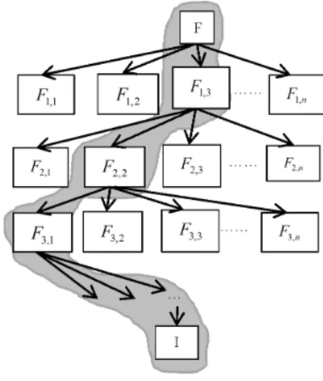
Search-based synthesis methods can be described as in Fig. 12. The method works by separating the entire permutation into a set of cycles and synthesize them separately. This divide and conquer method is effective against reversible functions that leave many inputs un-changed.
In [41], the authors’ algorithm uses the positive-polarity Reed-Muller decomposition at each stage to synthesize the function using only CNOT and C2NOT(Toffoli) gate. The primary objective of their algorithm is to minimize the number of gates (ie. fac-tors) needed to transform a PPRM expansion into the identity function. Their secondary objective is to min-imize the size of the individual gates (i.e. the num-ber of literals in each factor). In order to take advan-tage of shared functionality among multi-output
func-Fig. 12: Search-based synthesis algorithm.
tions, candidate factors are selected among common sub-expressions of PPRM expansions. However the method does not guarantee that the resulted PPRM expression contains fewer terms. In [42], the authors proposed a hybrid behavior of depth-first search (DFS) and breadth-first search (BFS) synthesis algorithm. Their algorithm is able to reduce the tree depth with-out decreasing the quality of results. In [43] improves the method of [41] by introducing Peres, reverse Peres and Fredkin gates into their search-based algorithm.
3.4.
Non-Search-Based Synthesis
Algorithm
In [11], the author proposed a non-search based syn-thesis algorithm. Compared with most widely used search-based methods whereby they evaluate all pos-sible gates to find an implementation of the circuits, this method cannot be used when synthesize large func-tions. However this can be avoided in non-search based synthesis algorithm as it is able to produce a solution for a given specification without evaluation of all pos-sible gates during each step. The synthesis algorithm is similar to [44] just that they have used multiple-controlled Toffoli gates with both positive and nega-tive controls. The algorithm works on the truth table into the identity function. The algorithm always con-verges and leads to a valid result very fast compared to search-based method. The following example shows a reversible function generates into its reversible circuit using the non-search based method.
Table 6 represents the truth table of transformation in each step of the reversible function. During each step of the transformation, a Karnaugh map is used to decide what gate to be used as seen in Fig. 13 and Fig. 14.
Tab. 6: Truth table representation.
F Step 1 Step 2 Step 3 a1a2a3 f1f2f3 f1f2f3 f1f2f3 f1f2f3 0 0 0 0 0 0 0 0 0 0 0 0 0 0 0 0 0 1 0 0 1 0 0 1 0 0 1 0 0 1 0 1 0 0 1 0 0 1 0 0 1 0 0 1 0 0 1 1 0 1 1 0 1 1 0 1 1 0 1 1 1 0 0 1 1 1 1 0 1 1 0 0 1 0 0 1 0 1 1 0 1 1 1 1 1 1 1 1 0 1 1 1 0 1 1 0 1 1 0 1 1 0 1 1 0 1 1 1 1 0 0 1 0 0 1 0 1 1 1 1 (a)f2(new) =f2⊕f1f3 (b)f3=f3⊕f1f¯3 (c)f1(new) =f2⊕f1f3
Fig. 13: Karnaugh map.
Fig. 14: Resulting final circuit.
3.5.
Rule-Based Synthesis Algorithm
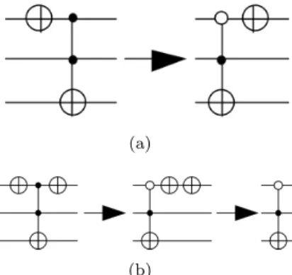
In [45] a rule-based optimization approach of reversible logic is introduced. The synthesis algorithm uses both positive and negative control Toffoli gate during the op-timization. A set of rules for removing NOT gates and optimizing sub-circuits with common-target gates are proposed. The synthesis algorithm can be broken into two steps, the first step uses NOT gates across a given reversible circuit to delete redundant NOT gate to im-prove the total circuit cost as can be seen in Fig. 15. Then the second step is to use a Karnaugh map-based optimization introduced in [46] to optimize sub-circuits with common-target gates as can be seen in one of the examples in Fig. 16 where the reversible circuit is fur-ther optimized using the Karnaugh map.
(a)
(b)
Fig. 15: Deleting redundant NOT gate.
(a)
(b)
Fig. 16: (a) Sub-circuit optimization (b) Truth table reduction.
3.6.
Transformation-Based Synthesis
Algorithm
In [47] a set of Toffoli based network transformation rules is introduced. The algorithm mainly served to bring a network to a canonical form. The transfor-mation is done based on six local transfortransfor-mation rules which are applied for a sequence of Toffoli based gates. The disadvantages of the approach are that it produces a high number of garbage bits. All the application rules were further extended in [44]. The synthesis algorithm synthesizes reversible function in terms ofn×nToffoli gates and uses several transformation rules on a set of predefined patterns called templates. The circuit is constructed by a single pass through the specifica-tion with a minimal look ahead and no back track-ing. Reduction rules are applied using simple template matching. The synthesis method works by comparing the truth table between the input and the output. For a given input or output, reversible gates are applied to transform them into identity function. To select which function to transform on which gate to be used, Hamming Distances between the input and output are
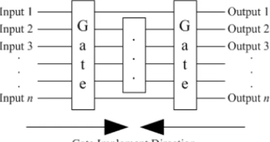
used. The algorithm iterates through the row of the truth table looking for the different in input and out-put and transforms them with multiple-control Toffoli gates. The function of the algorithm can be illustrated in Fig. 17.
Fig. 17: Gate implementation direction.
Later in [48] the synthesis of Toffoli networks are di-vided into two steps, the first step finds a network that realizes the desired function and the second stage trans-form the network such that it uses lesser gates while realizing the same function. In [49], the authors further improved the template matching algorithm proposed in the previous work in [48] by replacing the Hamming Distance method with the Reed-Muller Spectra. Us-ing the Reed-Muller Spectra, the reversible functions are represented in their PPRM expansion which can be easily substituted using reversible gates and thus improves in the overall synthesis result.
In [50], a modification of [44] is presented which transverse the truth table according to specially con-structed ordering of rows. Explicit storage of truth tables has also been avoided and the data for synthesis is represented implicitly allowing for the synthesis of very large functions.
3.7.
ESOR-Based Synthesis
Algorithm
In [3], the author has proposed an exclusive-or sum-of-products (ESOP)-based Toffoli gate cascade synthe-sis algorithm. The algorithm is capable of generating a cascade of reversible gates for large reversible func-tions. The algorithm uses a simple cost metric heuristic during a recursive divide and conquer function to deter-mine the placement of the NOT and Toffoli gate. For an ESOP represented function, the ESOP-based syn-thesis approach generates a circuit with2n+m lines, wheren is the number of inputs to the function andm is the number of outputs. The lastm circuit lines are assigned to 0 during initialization. Having those gates selected such that the desired function is realized. A single product xi1, ..., xik of an ESOP description di-rectly corresponds to a Toffoli gate with control lines
C = {xi1, ..., xik}. For those with negative
proposi-tional variable, NOT gates are applied to generate ap-propriate values (Toffoli gates withC= 1). Figure 18 shows an example of a reversible circuit generated us-ing ESOR-based synthesis method generated from the ESOP truth table in Tab. 7.
Tab. 7: ESOP truth table.
Input Output x1, x2,x3 y1,y2, y3 1 - 1 1 0 0 0 1 1 1 0 1 1 0 0 1 0 0 0 0 1 0 1 0 0 1 0
Fig. 18: ESOP resulting reversible circuit.
4.
Finding, Discussion and
Comparison
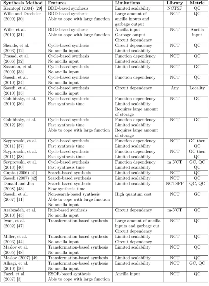
To analyze the effectiveness of reversible logic synthe-sis algorithms results, a certain benchmarking circuits are used. Benchmarking circuits are taken from [51] and [52] where these web pages offers a widely used re-versible benchmark functions and a list of the proposed algorithm review over the years. All benchmarking are clearly listed and their currently best known cir-cuit is presented. In Table 8 all the key features of each synthesis algorithm are listed. This table has five columns: 1st: describes synthesis methods proposed by researchers; 2nd: important feature considered for dif-ferent approaches; 3rd: Limitation of each algorithm; 4th: library function used and the last column indi-cates the metric.
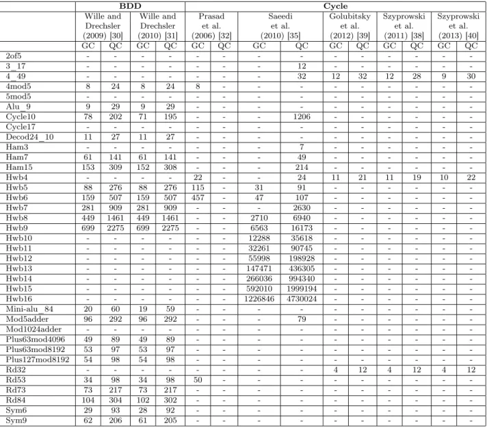
Table 9 shows those benchmarks functions with most synthesis algorithm comparing side by side in terms of gate count and quantum cost. For several synthesis al-gorithm which their synthesis result using benchmark-ing functions cannot be found are neglected. For those synthesis algorithms which are listed in Tab. 9, not all benchmarking result can be obtained, therefore for those we are not able to obtain, a symbol “-” are present in the table.
From Tab. 9, we observed that for the same ap-proaches, the newer algorithm has slightly improved
the synthesis outcome. For [31], as their algorithm re-duction is many circuit dependent therefore to have the condition met their algorithm for reduction are less. As a result, their synthesis algorithm outcome only slightly improved from their previous one [30]. For benchmarking functions which have less number of variable such as the4mod5, hwb5, sym6 where the function contain the most 6 variables, [43] and [49] can perform good simulation.
5.
Conclusion
Research in reversible logic has gain enthusiastic re-sponse for the computing technologies future. Research on reversible logic has been over the past 30 years [15]. Reversible logic library has been increased over the years from NOT, CNOT and Toffoli gate to multiple-controlled Toffoli gate and Peres gate. New synthe-sis techniques will always exist to replace the existing ones to more efficient synthesis Boolean function into reversible circuits. Despite the significant progress in reversible logic synthesis, several open challenges prob-lems will still remain.
References
[1] LANDAUER, R. Irreversibility and Heat Generation in the Computing Process. IBM Journal of Research and Development. 1961, vol. 5, iss. 3, pp. 183–191. ISSN 0018-8646. DOI: 10.1147/rd.53.0183.
[2] NEUMANN, J. V.Theory of Self-Reproducing Au-tomata.Urbana: University of Illinois Press, 1966. ISBN 978-0-2527-2733-7.
[3] FAZEL, K., M. A. THORNTON and J. E. RICE. ESOP-based Toffoli Gate Cascade Generation. In: IEEE Pacific Rim Conference on Communica-tions, Computers and Signal Processing 2007. Vic-toria: IEEE, 2007, pp. 206–209. ISBN 1-4244-1190-4.
[4] MACK, C. A. Fifty Years of Moore’s Law.IEEE Transactions on Semiconductor Manufacturing. 2011, vol. 24, iss. 2, pp. 202–207. ISSN 0894-6507. DOI: 10.1109/TSM.2010.2096437.
[5] HEY, T. Quantum Computing: An Introduc-tion.Computing & Control Engineering Journal. 1999, vol. 10, iss. 3, pp. 105–112. ISSN 1441-0460. DOI: 10.1049/cce:19990303.
[6] BENNETT, C. H. Logical Reversibility of Com-putation.IBM Journal of Research and Develop-ment.1973, vol. 17, iss. 6, pp. 525–532. ISSN 0018-8646. DOI: 10.1147/rd.176.0525.
[7] KNILL, E., R. FAFLAMME and G. L. MIL-BURN. A Scheme for Efficient Quantum Compu-tation with Linear Optics.Nature.2001, vol. 409, iss. 6816, pp. 46–52. DOI: 10.1038/35051009. [8] NIELSEN, M. A. and I. L. CHUNG. Quantum
Computation and Quantum Information.10th An-niversary ed. Cambridge: Cambridge University Press, 2000. ISBN 978-1-107-00217-3.
[9] MOHAMMADI, M., M. ESHGHI, M. HAGH-PARAST and A. BAHROLOLOOM. De-sign and Optimization of Reversible BCD Adder/Subtractor Circuit for Quantum and Nanotechnology Based Systems. World Applied Sciences Journal.2008. vol. 4, iss. 6, pp. 787–792. ISSN 1818-4952.
[10] HARI, S. K., S. SHROFF, S. MAHAMMAD and V. KAMAKOTI. Efficient Building Blocks for Re-versible Sequential Circuit Design. In: IEEE In-ternational Midwest Symposium on Circuits and Systems 2006. San Juan: IEEE, 2006, pp. 437– 441. ISBN 1-4244-0173-9. DOI: 10.1109/MWS-CAS.2006.382092.
[11] SAEEDI, M., M. SEDIGHI and M. S. ZAMANI. A Novel Synthesis Algorithm for Reversible Cir-cuits. In: IEEE/ACM International Conference on Computer-Aided Design 2007.San Jose: IEEE, 2007, pp. 65–68. ISSN 1092-3152. ISBN 978-1-4244-1382-9. DOI: 10.1109/ICCAD.2007.4397245. [12] SHENDE, V. V., A. K. PRASAD, I. L. MARKOV and J. P. HAYES. Synthesis of Reversible Logic Circuits. IEEE Transactions on Computer-Aided Design of Integrated Circuits and Systems. 2003, vol. 22, iss. 6, pp. 710–722. ISSN 0278-0070. DOI: 10.1109/TCAD.2003.811448.
[13] YANG, G., X. SONG, W. N. N. HUNG, F. XIE and M. PERKOWSKI. Group The-ory Based Synthesis of Binary Reversible Cir-cuits. In: Theory and Applications of Mod-els of Computation. Berlin: Springer, 2006. vol. 3959, pp. 365-374. ISBN 978-3-540-34022-5. DOI: 10.1007/11750321_35.
[14] PERKOWSKI, M., L. JOZWIAK, P. KERN-TOPF, A. MISHCHENKO and A. AL-RABADI. A General Decomposition for Reversible Logic. In: Reed-Muller Workshop 2001.pp. 119–138, 2001. [15] TOFFOLI, T. Reversible Computing.Automata,
Languages and Programming. Berlin: Springer, 1980, vol. 84, pp. 632–644. ISBN 978-3-540-10003-4. DOI: 10.1007/3-540-10003-2_10978-3-540-10003-4.
[16] FEYNMAN, R. Quantum Mechanical Com-puters. Foundations of Physics. 1985,
Tab. 8: Comparison table of all discussed synthesis methods.
Synthesis Method Features Limitations Library Metric
Kerntopf (2004) [29] BDD-based synthesis Limited scalability NCTSF QC Wille and Drechsler BDD-based synthesis Large amount of NCT QC (2009) [30] Able to cope with large function ancilla inputs and
garbage output
Wille, et al. BDD-based synthesis Ancilla input NCT Ancilla (2010) [31] Able to cope with large function Garbage output input
Circuit dependency
Shende, et al. Cycle-based synthesis Circuit dependency NCT QC (2003) [12] No ancilla input Limited scalability
Prasad, et al. Cycle-based synthesis Function dependency NCT QC (2006) [32] No ancilla input Limited scalability
Sasanian, et al. Cycle-based synthesis Limited scalability NCT GC (2009) [33] No ancilla input
Saeedi, et al. Cycle-based synthesis Function dependency NCT QC (2010) [34] No ancilla input
Saeedi, et al. Cycle-based synthesis Circuit dependency Any Locality (2010) [35] No ancilla input
Golubitsky, et al. Cycle-based synthesis Function dependency NCT GC (2010) [36] Fast synthesis time Limited scalability
Requires large amount of storage
Golubitsky, et al. Cycle-based synthesis Function dependency NCT GC (2012) [39] Fast synthesis time Limited scalability
Able to cope with large function Requires large amount of storage
Szyprowski, et al. Cycle-based synthesis Function dependency NCT GC then
(2011) [37] Fast synthesis time Limited scalability QC
Szyprowski, et al. Cycle-based synthesis Function dependency NCT GC then
(2011) [38] Fast synthesis time Limited scalability QC
Szyprowski, et al. Cycle-based synthesis Function dependency m NCT GC, QC
(2013) [40] Fast synthesis time Limited scalability QC
Gupta (2006) [41] Search-based synthesis Limited scalability NCT QC Saeedi (2007) [42] Search-based synthesis Limited scalability NCT QC Donald and Jha Search-based synthesis Limited scalability NCTSFP QC, QC (2008) [43] Slow synthesis time
Saeedi, et al. Non-search-based synthesis High quantum cost NCT GC (2007) [11] Able to cope with large function
No ancilla input
Arabzadeh, et al. Rule-based synthesis Circuit dependency m-NCT QC (2010) [45] No ancilla input
Iwan, et al. Transformation-based synthesis Large amount of ancilla NCT QC
(2002) [47] inputs and garbage out.
Circuit dependency
Miller, et al. Transformation-based synthesis Limited scalability NCT QC (2003) [44] No ancilla input Circuit dependency
Maslov et al. Transformation-based synthesis Limited scalability NCT QC (2005) [48] No ancilla input
Maslov (2007) [49] Transformation-based synthesis Limited scalability NCT QC Alhagi, et al. Transformation-based synthesis Limited scalability NCT GC, QC (2010) [50] No ancilla input
Fazel, et al. ESOR-based synthesis Ancilla input NCT QC
Tab. 9: Benchmark comparison.
BDD Cycle
Wille and Wille and Prasad Saeedi Golubitsky Szyprowski Szyprowski
Drechsler Drechsler et al. et al. et al. et al. et al.
(2009) [30] (2010) [31] (2006) [32] (2010) [35] (2012) [39] (2011) [38] (2013) [40] GC QC GC QC GC QC GC QC GC QC GC QC GC QC 2of5 - - - -3_17 - - - 12 - - - -4_49 - - - 32 12 32 12 28 9 30 4mod5 8 24 8 24 8 - - - -5mod5 - - - -Alu_9 9 29 9 29 - - - -Cycle10 78 202 71 195 - - - 1206 - - - -Cycle17 - - - -Decod24_10 11 27 11 27 - - - -Ham3 - - - 7 - - - -Ham7 61 141 61 141 - - - 49 - - - -Ham15 153 309 152 308 - - - 214 - - - -Hwb4 - - - - 22 - - 24 11 21 11 19 10 22 Hwb5 88 276 88 276 115 - 31 91 - - - -Hwb6 159 507 159 507 457 - 47 107 - - - -Hwb7 281 909 281 909 - - - 2630 - - - -Hwb8 449 1461 449 1461 - - 2710 6940 - - - -Hwb9 699 2275 699 2275 - - 6563 16173 - - - -Hwb10 - - - 12288 35618 - - - -Hwb11 - - - 32261 90745 - - - -Hwb12 - - - 55998 198928 - - - -Hwb13 - - - 147471 436305 - - - -Hwb14 - - - 266036 994340 - - - -Hwb15 - - - 592010 1999194 - - - -Hwb16 - - - 1226846 4730024 - - - -Mini-alu_84 20 60 19 59 - - - -Mod5adder 96 292 96 292 - - - 79 - - - -Mod1024adder - - - -Plus63mod4096 49 89 49 89 - - - -Plus63mod8192 53 97 53 97 - - - -Plus127mod8192 54 98 54 98 - - - -Rd32 - - - 4 12 4 12 4 12 Rd53 34 98 34 98 50 - - - -Rd73 73 217 73 217 - - - -Rd84 104 304 102 302 - - - -Sym6 29 93 28 92 - - - -Sym9 62 206 61 205 - - -
-Search Rule Transformation
Gupta Donald Arabzadeh Miller Maslov Maslov
et al. and Jha et al. et al. et al. et al.
(2006) [41] (2008) [43] (2010) [45] (2003) [44] (2005) [48] (2007) [49] GC QC GC QC GC QC GC QC GC QC GC QC 2of5 20 100 20 9 - - 12 32 13 32 - -3_17 6 14 5 11 - 13 6 12 - - 6 14 4_49 13 61 12 29 - 30 16 58 13 63 12 32 4mod5 9 25 5 13 - - 8 24 9 19 5 9 5mod5 11 91 11 91 - - 17 185 21 125 17 77 Alu_9 9 49 - - - 9 25 Cycle10 26 1435 - - - - 585 3867 19 1198 19 1206 Cycle17 - - - 48 6069 Decod24_10 11 31 11 31 - - - 7 19 Ham3 5 9 4 7 - - 5 7 4 10 5 9 Ham7 23 68 22 67 - - 23 81 21 65 25 49 Ham15 - - 132 1827 70 453 109 206 Hwb4 15 35 10 19 - - 17 63 11 81 11 23 Hwb5 35 175 - 101 55 313 24 248 24 104 Hwb6 - 140 126 1528 65 1171 42 140 Hwb7 - 2516 586 4385 236 3874 331 2611 Hwb8 - 6687 - - 637 16522 749 7013 Hwb9 - 20207 1544 44702 1541 44653 1959 22502 Hwb10 - 52225 - - 3595 136164 4540 59191 Hwb11 - 121830 - - 9314 345020 11600 136756 Hwb12 - - - -Hwb13 - - - -Hwb14 - - - -Hwb15 - - - -Hwb16 - - - -Mini-alu_84 21 173 - - - - 95 670 - - 36 248 Mod5adder 37 529 - - - 71 223 1379 17 77 17 81 Mod1024adder - - - 55 1575 Plus63mod4096 - - - 24 4873 Plus63mod8192 - - - 28 9183 Plus127mod8192 - - - 25 9131 Rd32 4 12 5 9 - - - -Rd53 13 116 17 78 - 62 28 117 16 75 16 65 Rd73 - - 20 64 20 64 1344 20779 Rd84 - - 28 98 28 98 124 8738 Sym6 36 777 - - - - 177 1340 20 62 15 119 Sym9 - - 362 2845 28 94 27 201
vol. 16, iss. 6, pp. 507-531. ISSN 0015-9018. DOI: 10.1007/BF01886518.
[17] FREDKIN, E. and T. TOFFOLI. Conserva-tion Logic. International Journal of Theoretical Physic. 1982, vol. 21, iss. 3–4, pp. 219–253. ISSN 0020-7748. DOI: 10.1007/BF01857727. [18] PERES, A. Reversible Logic and Quantum
Computers. Physic Review. 1985, vol. 32, iss. 6, pp. 3266–3276. ISSN 1079-7114. DOI: 10.1103/PhysRevA.32.3266.
[19] THAPLIYAL, H. and N. RANGANATHAN. De-sign of Efficient Reversible Binary Subtractors Based on A New Reversible Gate. In: IEEE Com-puter Society Annual Symposium on VLSI 2009. Tampa: IEEE, 2009, pp. 229–234. ISBN 978-1-4244-4408-3. DOI: 10.1109/ISVLSI.2009.49. [20] DIVINCENZO, D. P. Quantum computation.
Sci-ence.1995, vol. 270, pp. 255–261. ISSN 0036-8075. DOI: 10.1126/science.270.5234.255.
[21] DIRAC, P. A. M. A New Notation for Quantum Mechanics. Mathematical Proceedings of the Cambridge Philosophical Society. 1939, vol. 35, iss. 3, pp. 416–418. ISSN 1469-8064. DOI: 10.1017/S0305004100021162.
[22] HUNG, W. N. N., X. SONG, G. YANG, J. YANG and M. PERKOWSKI. Optimal Synthe-sis of Multiple Output Boolean Functions using a Set of Quantum Gates by Symbolic Reachabil-ity. IEEE Transactions on Computer-Aided De-sign of Integrated Circuits and Systems. 2006, vol. 25, iss. 9, pp. 1652–1663. ISSN 0278-0070. DOI: 10.1109/TCAD.2005.858352.
[23] BARENCO, A., C. H. BENNETT, R. CLEVE, D. P. DIVINCENZO, N. MARGOLUS, P. SHOR, T. SLEATOR, J. A. SMOLIN and H. WEIN-FURTER. Elementary Gates for Quantum Com-putation.Physical Review A.1995, vol. 52, iss. 5, pp. 3457–3467. DOI: 10.1103/PhysRevA.52.3457. [24] THAPLIYAL, T. N. and RANGANATHAN. De-sign of Reversible Sequential Circuits Optimiz-ing Quantum Cost, Delay, and Garbage Outputs. ACM Journal on Emerging Technologies in Com-puting Systems. 2010, vol. 6, iss. 4, pp. 1–31. ISSN 1550-4832. DOI: 10.1145/1877745.1877748. [25] DRECHSLER, R. and R. WILLE. From Truth
Ta-bles to Programming Languages: Progress in the Design of Reversible Circuits. In: IEEE Interna-tional Symposium on Multiple-Valued Logic 2011. Tuusula: IEEE, 2011, pp. 78—85. ISSN 0195-623X. ISBN 978-0-7695-4405-2. DOI: 10.1109/IS-MVL.2011.40.
[26] BRYANT, R. E. Graph-Based Algorithms for Boolean Function Manipulation. IEEE Transactions on Computers. 1986, vol. C-35, iss. 8, pp. 677–691. ISSN 0018-9340. DOI: 10.1109/TC.1986.1676819.
[27] JABIR, A. M., D. K. PRADHAN, A. K. SINGH and T. L. RAJAPRABHU. A Technique for Representing Multiple Output Binary Functions with Applications to Verification and Simula-tion. IEEE Transactions on Computers. 2007, vol. 56, iss. 8, pp. 1133–1145. ISSN 0018-9340. DOI: 10.1109/TC.2007.1056.
[28] SASAO, T. Logic Synthesis and Optimization. Boston, MA: Springer Verlag, 1993, vol. 212. ISBN 978-1-4613-6381-1.
[29] KERNTOPF, P. A New Heuristic Algorithm for Reversible Logic Synthesis. In: Proceed-ings of 41st Design Automation Conference 2004. San Diego: DAC, 2004, pp. 843– 837. ISSN 0738-100X. ISBN 1-51183-828-8. DOI: 10.1145/996566.996789.
[30] WILLE, R. and R. DRECHSLER. BDD-Based Synthesis of Reversible Logic for Large Functions. In: Proceedings of the 46th Annual Design Au-tomation Conference 2009. San Francisco: DAC, 2009, pp. 270–275. ISSN 0738-100X. ISBN 978-1-6055-8497-3. DOI: 10.1145/1629911.1629984. [31] WILLE, R., M. SOEKEN and R. DRECHSLER.
Reducing the Number of Lines in Reversible Cir-cuits. In: Proceedings of the 47th Design Au-tomation Conference 2010.Anaheim: DAC, 2010, pp. 647–652. ISSN 0738-100X. ISBN 978-1-4503-0002-5. DOI: 10.1145/1837274.1837439.
[32] PRASAD, A. K., V. V. SHENDE, I. L. MARKOV, J. P. HAYES and K. N. PATEL. Data Structures and Algorithms for Simplify-ing Reversible Circuits.ACM Journal of Emerg-ing Technologies in ComputEmerg-ing Systems. 2006, vol. 2, iss. 4, pp. 277–293. ISSN 1550-4832. DOI: 10.1145/1216396.1216399.
[33] SASANIAN, Z., M. SAEEDI, M. SEDIGHI and M. S. ZAMANI. A Cycle-Based Synthe-sis Algorithm for Reversible Logic. In: Asia and South Pacific Design Automation Confer-ence 2009.Yokohama: ASP-DAC, 2009, pp. 745– 750. ISBN 978-1-4244-2748-2. DOI: 10.1109/ASP-DAC.2009.4796569.
[34] SAEEDI, M., M. S. ZAMANI, M. SEDIGHI and Z. SASANIAN. Reversible Circuit Synthesis Us-ing a Cycle-Based Approach. ACM Journal on Emerging Technologies in Computing Systems. 2010, vol. 6, iss. 4, pp. 1–26. ISSN 1550-4832. DOI: 10.1145/1877745.1877747.
[35] SAEEDI, M., M. SEDIGHI and M. S. ZAMANI. A Library-Based Synthesis Methodology for Re-versible Logic. Microelectronics Journal. 2010, vol. 41, iss. 4, pp. 185–194. ISSN 0026-2692. DOI: 10.1016/j.mejo.2010.02.002.
[36] GLOUBITSKY, O., S. M. FALCONER and D. MASLOV. Synthesis of The Optimal 4-bit Re-versible Circuits. In: Proceedings of the 47th Design Automation Conference 2010. Anaheim: DAC, 2010, pp. 653–656. ISBN 978-1-4503-0002-5. DOI: 10.1145/1837274.1837440.
[37] SZPROWSKI, M. and P. KERNTOPF. Reducing Quantum Cost in Reversible Toffoli Circuits. In: Reed-Muller Workshop 2011.pp. 127–136, 2011. [38] SZPROWSKI, M. and P. KERNTOPF. An
Ap-proach to Quantum Cost Optimization in Re-versible Circuits. In: 11th IEEE Conference on Nanotechnology 2011. Portland: IEEE, 2011, pp. 1521–1526. ISSN 1944-9399. ISBN 978-1-4577-1515-0. DOI: 10.1109/NANO.2011.6144568. [39] GOLUBITSKY, O. and D. MASLOV. A Study
of Optimal 4-Bit Reversible Toffoli Circuits and Their Synthesis.IEEE Transactions on Comput-ers.2012, vol. 61, iss. 9. pp. 1341–1353. ISSN 0018-9340. DOI: 10.1109/TC.2011.144.
[40] SZYPROWSKI, M. and P. KERNTOPF. Opti-mal 4-bit Reversible Mixed-Polarity Toffoli Cir-cuits. Reversible Computation. Berlin: Springer, 2013. vol. 7581, pp. 138–151. ISSN 0302-9743. ISBN 978-3-642-36315-3. DOI: 10.1007/978-3-642-36315-3_11.
[41] GUPTA, P., A. AGRAWAL and N. K. JHA. An Algorithm for Synthesis of Reversible Logic Cir-cuits.IEEE Transactions on Computer-Aided De-sign of Integrated Circuits and Systems. 2006, vol. 25, iss. 11, pp. 2317–2330. ISSN 0278-0070. DOI: 10.1109/TCAD.2006.871622.
[42] SAEEDI, M., M. S. ZAMANI and M. SEDIGHI. On the Behavior of Substitution-based Reversible Circuit Synthesis Algorithm Investigation and Im-provement. In: IEEE Computer Society Annual Symposium on VLSI 2007. Washington: IEEE, 2007, pp. 428–436. ISBN 0-7695-2896-1. DOI: 10.1109/ISVLSI.2007.72.
[43] DONALD, J. and N. K. JHA. Reversible Logic Synthesis with Fredkin and Peres Gates. ACM Journal on Emerging Technologies in Computing Systems.2008, vol. 4, iss. 1, pp. 1–19. ISSN 1550-4832. DOI: 10.1145/1330521.1330523.
[44] MILLER, D. M., D. MASLOV and G. W. DUECK. A Transformation Based Algorithm for
Reversible Logic Synthesis. In: Proceedings of the 40th annual Design Automation Conference 2003. New York: DAC, 2003, pp. 318–323. ISBN 1-58113-688-9. DOI: 10.1109/DAC.2003.1219016. [45] ARABZADEH, M., M. SAEEDI and M. S.
ZA-MANI. Rule-Based Optimization of Reversible Circuits. In: Proceedings of the 2010 Asia and South Pacific Design Automation Confer-ence 2010. Taipei: ASP-DAC, 2010, pp. 849– 854. ISBN 978-1-4244-5767-0. DOI: 10.1109/AS-PDAC.2010.5419684.
[46] WANG, S. A., C. Y. LU, I. M. TSAI and S. Y. KUO. Modified Karnaugh Map for Quantum Boolean Circuits Construction. In: IEEE Con-ference on Nanotechnology 2003. Taipei: IEEE, 2003, vol. 2, pp. 651–654. ISBN 0-7803-7976-4. DOI: 10.1109/NANO.2003.1230996.
[47] IWAN, K., Y. KAMBAYASHI and S. YA-MASHITA. Transformation Rules for Design-ing CNOT-based Quantum Circuits. In: Pro-ceedings of the 39th annual Design Automa-tion Conference 2002. New York: IEEE, 2002, pp. 419–424. ISSN 0738-100X . ISBN 1-58113-461-4. DOI: 10.1109/DAC.2002.1012662.
[48] MASLOV, D., G. W. DUECK and D. M. MILLER. Toffoli Network Synthesis With Tem-plates. IEEE Transactions on Computer-Aided Design of Integrated Circuits and Systems. 2008, vol. 24, iss. 6, pp. 807–817. ISSN 0278-0070. DOI: 10.1109/TCAD.2005.847911.
[49] MASLOV, D., G. W. DUECK and D. M. MILLER. Techniques for the Synthesis of Re-versible Toffoli Networks. ACM Transactions on Design Automation of Electronic Systems. 2007, vol. 12, iss. 4, pp. 1–42. ISSN 1084-4309. DOI: 10.1145/1278349.1278355.
[50] ALHAGI, N., M. HAWASH and M. PERKOWSKI. Synthesis of Reversible Cir-cuits with No Ancilla Bits for Large Reversible Functions Specified with Bit Equations. In: IEEE International Symposium on Multiple-Valued Logic 2010. Barcelona: IEEE, 2010, pp. 39– 45. ISSN 0195-623X. ISBN 978-1-4244-6752-5. DOI: 10.1109/ISMVL.2010.16.
[51] Reversible Benchmarks [online]. 2011. Reversible Logic Synthesis Benchmarks Page. Available at: http://webhome.cs.uvic.ca/ dmaslov/.
[52] Revlib [online]. 2013. An Online Resourse for Reversible Functions and Reversible Cir-cuits. Available at: http://www.informatik.uni-bremen.de/rev_lib/.
About Authors
Shin Cheng CHUA received Bachelor degree in Electronics and Communication Engineering from Curtin University and currently is a researcher in the Department of Electrical and Computer Engineering of Curtin University. His research of interest includes reversible logic, artificial neural network and PID controller.
Ashutosh KUMAR SINGH obtained his Ph.D. degree in Electronics Engineering from Institute of Technology, Banaras Hindu University, India and Post Doc from Department of Computer Science, University of Bristol, United Kingdom.
His Research area includes Multi agent System, Ver-ification, Synthesis, Design and Testing of Digital Cir-cuits. He has published more than 70 research pa-pers till now in different journals, conferences and news magazines and in these areas. He is a co-author of two books “Digital Systems Fundamentals” and “Com-puter System Organization & Architecture” with Pren-tice Hall.
He had delivered the invited talks and pre-sented research papers in several countries
including Australia, United Kingdom, South Korea, China, Thailand, India and USA. He had been enti-tled for the awards such as Merit Award-03 (Institute of Engineers), Best Poster Presenter-99 in 86th Indian Science Congress held in Chennai, INDIA, Best Paper Presenter of NSC’99 INDIA.
Currently he is an Editorial Board Member of In-ternational Journal of Networks and Mobile Technolo-gies, International journal of Digital Content Technol-ogy and its Applications. Also has shared his experi-ence as a Guest Editor for Pertanika Journal of Sci-ence and Technology, Chairman of CUTSE Interna-tional Conference 2011 and as editorial board mem-ber of UNITAR e-journal. He is involved in reviewing process in different journals and conferences such as; IEEE transaction of computer, IET, IEEE conference on ITC, ADCOM etc.
Presently he is leading two research grants and supervising three Higher Degree Research students. He has worked as a Principal Investigator on a research project “Application of Decision Diagrams in Synthesis, Design and Testing of VLSI” in Malaysia. He was a key member on a project from EPSRC (United Kingdom) “Logic Verification and Synthesis in New Framework”.