for Texture Rendering on Bare Finger
Micha¨el Wiertlewski1, Daniele Leonardis1,2, David J. Meyer1,Michael A. Peshkin1, and J. Edward Colgate1 1
Department of Mechanical Engineering Northwestern University, Evanston, Il, 60208, USA
{wiertlewski;peshkin;colgate}@northwestern.edu [email protected] 2 PERCRO Laboratory, Scuola Superiore SantAnna, 56127 Pisa, Italy
Abstract. We present the design and evaluation of a high fidelity surface-haptic device. The user slides a finger along a glass plate while friction is controlled via the amplitude modulation of ultrasonic vibrations of the plate. A non-contact finger position sensor and low latency render-ing scheme allow for the reproduction of fine textures directly on the bare finger. The device can reproduce features as small as 25µm while maintaining an update rate of 5 kHz. Signal attenuation, inherent to resonant devices, is compensated with a feedforward filter, enabling an artifact-free rendering of virtual textures on a glass plate.
Keywords: Surface-haptics, texture rendering, finger friction, feedfor-ward filtering, high fidelity haptics.
1
Introduction
The tactile perception of texture is influenced by a wide set of physical properties including roughness at multiple length scales, skin-surface adhesion, and surface deformability [1]. Each of these properties, along with the mechanics of the finger itself, contribute to frictional losses which relate to the perception of slipperiness and stickiness [2], as well as vibrations which relate to perceived roughness [3]. A challenge that faces the designers of haptic interfaces is emulating a wide range of tactile experiences with control over a substantially reduced set of physical variables.
Rendering Tactile Texture on a Bare Fingertip. One variable that lends itself to control is the net force acting on a fingertip. Thus, a large body of work has been devoted to the reproduction of texture using force-feedback devices [4]. While these allow for complex simulations, they are often poorly suited to the very fine temporal and spatial scales of texture [5]. These limitations can be circumvented with vibrotactile actuators. The reproduction of the friction force as a vibration correlated with the motion of the fingers allows the rendering of complex roughness profiles. However, because vibrotactile actuation is limited to frequencies higher than 20 Hz, the quasi-static content is not represented which implies that the stickiness dimension of the texture cannot be controlled [6].
Ultrasonic Modulation of Friction. The friction reduction effect was first described by Watanabe et Fukui [7]. They noticed that, when touching a plate excited by out-of-plane ultrasonic vibrations, users experienced reduced friction. Subsequently it has been shown that modulation of friction correlated with fin-ger motion enables rendering of coarse gratings [8, 9]. But the refresh rate and position resolution of previous devices has limited the fineness of spatial patterns that can be rendered. In addition, the physics of high-Q resonant systems limits the bandwidth at which the amplitude can be modulated [10, 11].
Present Study. We address the previously-mentioned limits by implementing high performance hardware and a rendering scheme that achieve performance comparable to the known psychophysical threshold of human tactile perception. A custom-made non-contact position sensor and a fast rendering processor allow friction to be controlled with a 5 kHz refresh rate and 8µm position resolution. The high-performance piezoelectric actuators used in this device allow for a high dynamic range of friction force. Lastly, the amplitude modulation dynamics is compensated using feedforward filters, providing a flat frequency response over the entire bandwidth of human tactile perception.
2
Human Factors
The ideal device has infinite bandwidth, spatial resolution and force resolution. We can approach this ideal by designing a device with enough quality that it will be indistinguishable from the ideal case. This section reviews the psychophysics and biomechanics involved in the perception of vibratory and frictional cues in order to draw specifications for a high-fidelity rendering device.
Temporal Resolution: It is well established that the maximum frequency that can be felt by the human somatosensory system is about 800 Hz [12]. In terms of latency between the user motion and the force rendering, a 30 ms delay has been reported as unnoticeable while exploring virtual vibrotactile surfaces [13]. Spatial Resolution: The smallest grating a human can perceive will depend on the speed of the exploration. Considering a slow exploration speed of 40 mm/s [14] and the previously-mentioned frequency limit of f = 800 Hz, we estimate that the smallest perceptible wavelength is on the order of λ=v/f = 50 µm. The estimate is consistent with [15].
Force Resolution and Dynamic Range: Millet et al. estimated the smallest static force that a human can perceive is 10−2N [16]. However tactile perception is much more sensitive to transients than to static stimulation. Considering that the smallest displacement perceptible is in the order of 10−7 m at 300 Hz [17], and that the impedance of the finger pad at this frequency is approximately 3 N.s/m [18], the smallest dynamic forces that can be perceived should be closer to 5.10−4 N. Considering that texture exploration is usually achieved with nor-mal force in the vicinity of 0.5 N [14], and that a typical coefficient of friction (before reduction) is unity, it is necessary to display a peak lateral force of 0.5 N. This suggests that a dynamic range of 103 is sufficient.
3
High-Speed High-Resolution Rendering
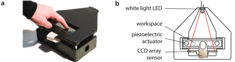
Fig. 1a shows a picture of the device and Fig. 1b presents a schematic of its components. An optical sensor captures the position of the finger at a rate of 5 kHz and with a spatial resolution of 8µm. From this position value, a command value is computed and output at the same rate, then mixed with a 30 kHz carrier. The signal is fed to the piezoelectric actuators that produce ultrasonic vibration of the glass touch surface. If we compare to the limits derived in paragraph 2, the current setup can render an 800 Hz temporal sine wave and a 50µm spatial wavelength both with a margin of 6.25 samples per period. The high refresh rate allows for robust rendering even with exploration speeds up to 250 mm/s [5].
white light LED
CCD array sensor piezoelectric actuator workspace a b
Fig. 1. a. Picture of the high-fidelity device.b. The internals of the device. The user touches the glass plate undergoing ultrasonic vibration. The finger casts a shadow on the photodiode array sensor.
3.1 Rendering Scheme
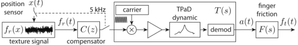
Texture rendering uses the process illustrated in Fig. 2. The texture signal is stored on a micro-controller (pic32mx250, Microchip Inc., Itasca, il, usa) as
a force-position profile. Every 200 µs, the position of the finger, acquired by the optical sensor later described, is used to fetch the force value in the stored profile and after applying a correction filter, is converted to analog using a 12-bit digital-to-analog converter (mcp4922, Microchip Inc., Itasca,il, usa). This
signal modulates the carrier frequency using an analog multiplier (ad633,
Ana-log Devices Inc., Northwood, ma, usa) and is then fed to a ±100 V amplifier
(pdm200, PiezoDrive, Pty Ltd, Callaghan, Australia) which excites the
piezo-electric actuators glued to the glass. This produces an amplitude-modulated drive signal with a sine wave at the resonance frequency as carrier, and the tex-ture waveform as modulation signal. The interaction between the finger and the vibrating glass creates a demodulation. The user experiences only changes in amplitude but has no perception of the ultrasonic carrier.
3.2 Non-contact Position Sensor
The finger position system employs an array of 1536 photodiodes (tsl1412s, ams-taosInc,tx, usa) with a pitch of about 64 microns. A diffuse white LED
compensator position sensor C(z) carrier TPaD dynamic demod fr(x) x(t) fr(t) finger friction ft(t) a(t) texture signal 5 kHz T(s) F(s)
Fig. 2.Mixed analog/digital rendering scheme. From the position of the fingerx(t) and a stored texture waveformfr(x), a force commandfr(t) is generated. This signal is then fed into a compensation filterC(z) which corrects for the amplitude-modulation dynamicsT(s) and the fingertip interactionF(s).
the surface, a shadow is cast on the photodiodes. Each of the photodiodes is connected to a charge amplifier and sampled at 5 kHz. The data is multiplexed into a time-domain signal that is processed in analog electronics. A low-pass filter resolves the average light level, and a comparator determines the presence of the finger. If the finger is in front of a pixel, it will read a lower voltage than average. The resulting signal is a pulse-position modulated signal, in which the finger position is encoded. After digitization, the centroid of the finger is determined with a resolution of 8µm and an update rate of 5 kHz.
3.3 Friction modulation device
The friction reduction device is based on a 135×25×3.2 mm3 borosilicate sub-strate. Thef0= 30 kHz resonant frequency corresponds to a (0,1) normal mode with free boundaries, see Fig. 3a and 3b. Dimensions were calculated to cancel any standing wave in the longitudinal direction and thus offer constant friction reduction properties over the full length of the touch surface. Low-loss piezoelec-tric actuators (smd19t03112s, Steminc and Martins Inc, Miami,fl, usa) are
glued on the plate to provide actuation. At resonance, the assembly deforms up to 4.8 µm under 50 V excitation and exhibits a quality factor ofQ= 300 when unloaded. A measurement of quasi-static friction reduction is shown Fig. 3c. The high voltage-to-amplitude gain of this device allows feedforward compensation to be implemented without encountering saturation.
a vibr ation amplitude (nm/V ) frequency (kHz) 29 31 0 2 0 1 2 amplitude (µm) 0 1 for ces (N) µ fn ft µ= ft fn nodal lines b c 100 1 10 unloaded Q = 300 light touch Q ~ 200
4
Compensation Filters
The resonant behavior of the plate limits the rate of change of the amplitude of the ultrasonic vibration. This has the effect of attenuating modulation frequen-cies above f0
2Q. With a finger touching the surface (which reduces Q), this cutoff
frequency is typically on the order of 75 Hz. The relatively large impedance of the glass plate dominates the impedance of the finger, as a result the frequency response is only slightly affected by the variation of finger stiffness or pressure applied. In addition, the frictional mechanics of the finger also introduces atten-uation. In [11], we characterized the attenuation of the amplitude of vibration a(t) and the magnitude of the friction force oscillations ft(t) with respect to a
sinusoidal reference signal fr(t). The former is well described by a first order
filter while the latter exhibits a non-trivial frequency response. Without cor-rection, attenuation will cause the amplitude of spatial gratings to vary with scanning velocity, resulting in a perceptual inconsistency. This section presents two approaches to correct for attenuation, and to provide a uniform frequency response over a wide range of frequencies.
4.1 Lead-Lag Compensator
The first order attenuation of the vibration amplitude can be corrected with the help of a lead-lag controller. Ideally, the device should have a flat response betweendcand 800 Hz, which translates intoC(s)T(s) =1+Qτws withτw= 0.2 ms. Uncompensated, the attenuation is well described by T(s) = 1+Qτ
rs with τ−1
r =2ωQ0. Therefore the lead-lag controller in continuous time isC(s) =
1+τrs 1+τws. We implemented the controller in discrete time using Tustin’s approximation. 4.2 Higher-Order Correction Filter
The lead-lag compensator provides a simple and effective way to enhance high-frequency content but is limited to correcting the amplitude attenuation, and does not address effects due to the frictional mechanics of the finger. Using a higher order filter, these effects can be addressed as well. The transfer function that relates the desired forcefr to the actual friction forceftisC(s)T(s)F(s),
where F(s) models the friction force as a function of the vibration amplitude. The identification of F(s) and potential explanation for its behavior has been covered in [11]. Here, we used a swept-sine signal lasting 2 seconds to identify the behavior. From the identified transfer function of the system, the controller was designed to be C(s)∝ ((1 +τw)T(s)F(s))−1. The controller is estimated
in discrete-time by a Yule-Walker optimization. Good agreement between ideal and actual filters is found using a bilinear filter of order 10 or above.
4.3 Experimental results
We experimentally measure the frequency bandwidth of the force modulation us-ing a stiff piezoelectric force sensor that can resolve 50µN up to 800 Hz (9203,
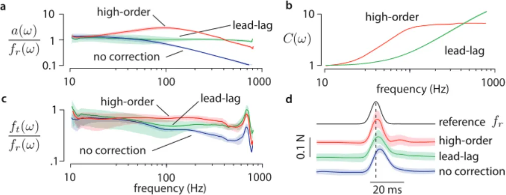
Kistler Instrumente AG, Winterthur, Switzerland). The ultrasonic vibration of the glass was measured using a piezoelectric pickup glued to the glass and cali-brated with a laser Doppler vibrometer. The full bandwidth was measured using 3 second swept-sine signals covering a 10-800 Hz band. The first two authors participated in the experiment. Before the experiment, they trained to maintain a scanning velocity of 40 mm/s and a normal force of 0.5 N. They applied talc to the fingertip before each session to ensure consistent moisture levels and took ten measurements, five going from left to right and five going from right to left. The amplitude-modulation frequency responses for the non-filtered, the lead-lag controller and the higher order filter cases are shown in Fig. 4a. Both average and standard deviation are shown for each case. Fig. 4b shows the action of each controller. Fig. 4c shows the friction force frequency response for each case. The high frequencies show a resonance that is attributed to the force sensing system. The high-order filter produces the flattest friction force response. However, de-spite its simplicity the lead-lag compensator also provides satisfactory results. The effectiveness of this system at displaying a feature in space is demonstrated using a Gaussian-shaped friction profile of 20 ms of width. The spatial tracking performance is shown in Fig. 4d.
a b 10 1000 C(ω) 10 frequency (Hz) 1000 1 0.1 10 1 20 ms no correction high-order lead-lag 10 frequency (Hz) 1000 1 .1 10 c d no correction lead-lag high-order 100 100 0.1 N fr a(ω) fr(ω) ft(ω) fr(ω) lead-lag high-order reference high-order lead-lag no correction
Fig. 4. a.Frequency response of amplitude modulation.b.Frequency response of com-pensators.c.Frequency response of the friction force acting on a sliding finger.d.Time domain performance.
5
Conclusion
We presented the design and implementation of a surface haptic display able to modulate friction on a bare fingertip with a high dynamic range and wide bandwidth. With the help of a novel non-contact position sensor, an efficient friction-reduction glass plate and correction filtering, the system provides high-fidelity in the rendering of rapid transient changes of friction. High-order filters achieve a better flatness of the force frequency response and a better time-domain tracking performance, at the expense of a more complex implementation. The lead-lag compensator provides good results with a lower performance footprint
that makes it suitable for embedded implementation. A further refinement could include a feedback loop to control the amplitude, although this would require real-time monitoring of the vibration of the plate.
The resulting device can render features as small as 25µm with high temporal accuracy. The high spatial resolution and low latency of the system gives the user a strong sense of the spatial persistence of tactile features that, to the best of our knowledge, has never been achieved before on surface haptic devices. The flatness of the frequency response enables a fine spatial grating to be consistently reproduced regardless of the scanning velocity. In the future we plan to perform a psychophysical evaluation of the perceived quality of the rendered textures.
Acknowledgements
This work has been supported by the National Science Foundation, grants No. IIS-0964075 and IIS-1302422. The authors acknowledge the help of Daniel Russ-man in the development of the experimental platform.
References
1. Bergmann-Tiest, W.M., Kappers, A.M.L.: Analysis of haptic perception of ma-terials by multidimensional scaling and physical measurements of roughness and compressibility. Acta Psychologica121(1) (2006) 1–20
2. Smith, A.M., Chapman, C.E., Deslandes, M., Langlais, J.S., Thibodeau, M.P.: Role of friction and tangential force variation in the subjective scaling of tactile roughness. Experimental Brain Research144(2) (2002) 211–223
3. Bensma¨ıa, S., Hollins, M.: The vibrations of texture. Somatosensory & motor research20(1) (2003) 33–43
4. Minsky, M., Lederman, S.: Simulated haptic textures: Roughness. In: Proceedings of the ASME Dynamic Systems and Control Division. Volume 58. (1996) 421–426 5. Campion, G., Hayward, V.: Fundamental limits in the rendering of virtual haptic
textures. In: World Haptics Conference, IEEE (2005) 263–270
6. Wiertlewski, M., Lozada, J., Hayward, V.: The spatial spectrum of tangential skin displacement can encode tactual texture. IEEE Transactions on Robotics 27(3) (2011) 461–472
7. Watanabe, T., Fukui, S.: A method for controlling tactile sensation of surface roughness using ultrasonic vibration. In: IEEE ICRA. (May 1995) 1134 –1139 8. Biet, M., Giraud, F., Lemaire-Semail, B.: Squeeze film effect for the design of an
ultrasonic tactile plate. Ultrasonics, Ferroelectrics and Frequency Control, IEEE Transactions on54(12) (2007) 2678–2688
9. Winfield, L., Glassmire, J., Colgate, J.E., Peshkin, M.: T-pad: Tactile pattern display through variable friction reduction. In: World Haptics Conference, IEEE (2007) 421–426
10. Giraud, F., Amberg, M., Lemaire-Semail, B.: Design and control of a haptic knob. Sensors and Actuators A: Physical (2013)
11. Meyer, D.J., Wiertlewski, M., Peshkin, M., Colgate, J.E.: Dynamics of ultrasonic and electrostatic friction modulation for rendering texture on haptic surfaces. In: Proceedings of Haptic Symposium. IEEE (2014) 218–226
12. Bolanowski Jr, S.J., Gescheider, G.A., Verrillo, R.T., Checkosky, C.M.: Four chan-nels mediate the mechanical aspects of touch. The Journal of the Acoustical society of America84(1988) 1680
13. Okamoto, S., Konyo, M., Saga, S., Tadokoro, S.: Detectability and perceptual consequences of delayed feedback in a vibrotactile texture display. Haptics, IEEE Transactions on2(2) (2009) 73–84
14. Smith, A.M., Gosselin, G., Houde, B.: Deployment of fingertip forces in tactile exploration. Experimental Brain Research147(2) (2002) 209–218
15. Skedung, L., Arvidsson, M., Chung, J.Y., Stafford, C.M., Berglund, B., Rutland, M.W.: Feeling small: Exploring the tactile perception limits. Scientific reports3 (2013)
16. Millet, G., Haliyo, S., Regnier, S., Hayward, V.: The ultimate haptic device: First step. In: World Haptics Conference, IEEE (2009) 273–278
17. Verrillo, R.T.: Effect of contactor area on the vibrotactile threshold. The Journal of the Acoustical Society of America35(1963) 1962
18. Wiertlewski, M., Hayward, V.: Mechanical behavior of the fingertip in the range of frequencies and displacements relevant to touch. Journal of biomechanics45(11) (2012) 1869–1874