www.ijres.org Volume 6 Issue 8 Ver. II ǁ 2018 ǁ PP. 31-35
NUMERICAL STUDY ON THE AIR HEATING FOR
INJECTION MOLD
Pham Son Minh
1, Aand Phan The Nhan
1, B1University of Technology and Education, Hochiminh City, Vietnam
Corresponding Author: Pham Son Minh
ABSTRACT: Gas-assisted mold temperature control (GMTC) is a new technology in the field of mold temperature control, which can heat and cool a cavity surface rapidly during the injection molding process. In this study, a gas-assisted mold surface heating system was simulated with different heating areas. The temperature distribution of the stamp inserts and the influence of the stamp size was observed. The results show that higher temperatures will occur at the center of the stamp insert due to the location of the gas inlet. In addition, the larger the size of the stamp, the lower heating rate that could be achieved.
KEYWORDS: injection molding, mold heating, dynamic mold temperature control, air heating.
--- Date of Submission:05-11-2018 Date of acceptance:19-11-2018 --- ---
I. INTRODUCTION
Injection molding is a popular technology for manufacturing. However, as parts become thinner and smaller, they become difficult to manufacture using conventional injection molding, because heat transfers rapidly from the melt to mold wall due to the thinness of the parts. Increasing the mold temperature, melt temperature, or packing pressure increases the cycle time. At higher mold surface temperatures, the surface quality of the part will improve [1, 2]. In the injection molding field, micro injection molding is being used to manufacture a variety of polymer components, because of its low cost and potential for high-volume production. Most applications are in the field of micro optics (such as CDs and DVDs) and micro fluidic devices. Production of other molded micro optical components including optical gratings, optical switches and waveguides [3 - 5], and a variety of molded micro fluidic devices including pumps, capillary analysis systems and lab-on-a-chip applications [6, 7].
In general, for improvement f an injection-molded part while minimizing part thickness and injection pressure, a higher mold temperature during injection is needed. However, maintaining a high mold temperature during the filling process, while ensuring it does not exceed the deflection temperature during the post-filling process, without significant increases in cycle time and energy consumption can be challenging. To solve this problem, a variety of dynamic mold temperature controls have been explored in recent years. The goal is to eliminate the heat loss from the melt to the mold, ideally producing a hot mold during the filling stage and a cool mold for the cooling stage. The most inexpensive way to achieve a high mold temperature is to use water at temperatures as high as 90˚C or 100˚C [8].
Another heating method is local mold heating using an electric heater [9], which can be used to assist high mold temperature control. However, this requires additional design and tooling costs. Furthermore, electrical heating is usually only used as an auxiliary heating method, and it is limited to increases in mold temperature of roughly several tens of degrees centigrade. Other mold surface heating techniques, such as induction heating [10 - 12], high-frequency proximity heating [13, 14], and gas-assisted mold temperature control (GMTC) [15, 16] can provide sufficient heating rates without significant increases in cycle time. In recent years, we provide a systematic study on mold surface heating and mold surface localization heating of the processing characteristics.
II. SIMULATION METHOD
Figure 1. Gas heating model
In this research, the hot gas generator consists of an air compressor, an air dryer, a gas valve for volumetric control of the flow, and a high-efficiency gas heater. The function of the high power hot gas generator system is to support a heat source, which provides a flow of hot air up to 500 °C with an inlet gas pressure up to 7 MPa. For the coolant system, a temperature controller was used to provide water at a defined temperature to cool the mold after the filling process and to warm the mold to the initial temperature at the beginning of the cycle. The valve system was used to control the water for cooling channels and the air for the heating stage. To control and observe the temperature at the cavity surface, three temperature sensors were used to obtain the real time mold temperature and to provide feedback to the GMTC controller.
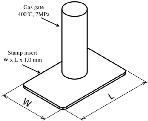
In this paper, the hot gas will be used as a heating source to increase the cavity surface temperature of the injection mold. This hot gas will heat the cavity surface to the target temperature. The heating step will be simulated with the model as shown in Figure 1. The heating process will be observed with different heating areas, as shown in Figure 2. In the simulation, 400 °C gas will be setup at the gas inlet with a pressure of 7 MPa. The stamp thickness is 1.0 mm with the width and the length shown in Table 1. In the simulation, ANSYS software will be used with the meshing model as shown in Figure 3, with boundary condition of gas flow as shown in Figure 4. To investigate the influence of the heating area on the heating process, a parametric study with a range of heating areas shown in Table 1 will be conducted. The comparison will be conducted using the center point, as shown in Figure 5.
Stamp insert W x L x 1.0 mm
Gas gate 400oC, 7MPa
Figure 3. The mesh for the model
Gas Inlet
Gas Outlet
Stamp insert
Figure 4. The boundary conditions for gas flow
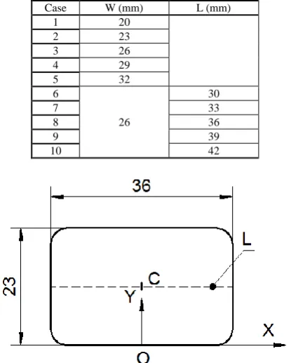
Table 1. Parameters for parametric study to investigate stamp size (heating area)
Case W (mm) L (mm)
1 20
2 23
3 26
4 29
5 32
6
26
30
7 33
8 36
9 39
10 42
Figure 5. Schematic of the stamp showing the location of the temperature measurement.
III. RESULT AND DISCUSSION
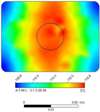
The simulation results in a temperature distribution of the stamp insert as shown in Figure 6. In this case, the size of stamp is 23 mm x 36 mm x 1.0 mm, and the heating time is 10 s. This result shows that the high temperature will focus at the center of the stamp, due to the gas inlet. The results also show that the heating rate is about 7 °C/s with an initial temperature of 30 °C and a max temperature of 101.0 °C, measured at point C in Figure 5.
gas is nearly the same. Therefore, the result is a lower temperature at the end of the same heating time for a larger stamp surface.
Figure 6. Temperature distribution of the heating area
Table 2. Temperature measurement at C with different length of heating area
A (mm) T (mm) W (mm) L (mm) T max (°C)
3 1.5 26
30 101.7
33 100.8
36 99.1
39 97.9
42 96.4
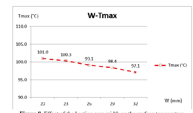
Table 3. Temperature measurement at C with different width of heating area
A (mm) T (mm) W (mm) L (mm) Tmax (°C)
3 1.5
20
36
101.0
23 100.3
26 99.1
29 98.4
32 97.1
Figure 8. Effect of the heating area width on the surface temperature
IV. CONCLUSION
In this study, a gas-assisted mold surface heating system was simulated with different heating areas. The temperature distribution of the stamp insert and the influence of the stamp size was observed. The results show that:
• The higher temperature will occur at the center of stamp insert due to the proximity to the gas inlet valve. • A larger stamp will result in a lower heating rate and a lower temperature that could be achieved.
REFERENCES
[1]. K. Yao, F. Gao, F. Allgöwer, Barrel temperature control during operation transition in injection molding, Elsevier, Control Engineering Practice, Vol.16, No.11, 1259–1264.
[2]. S. J. Liu, , P. C. Su, Novel three-dimensional in-cavity transient temperature measurements in injection molding and fluid-assisted injection molding, Elsevier, Polymer Testing, Vol.28, No.1, 66–74.
[3]. L. Liu, X. L. Ni, H. Q. Yin, X. H. Qu, Mould ability of various zirconia micro gears in micro powder injection moulding, Elsevier, Journal of the European Ceramic Society, Vol. 35, No.1, 171–177.
[4]. M. Rahimi, M. Esfahanian, M. Moradi, Effect of reprocessing on shrinkage and mechanical properties of ABS and investigating the proper blend of virgin and recycled ABS in injection molding, Elsevier, Journal of Materials Processing Technology, Vol.214, No.11, 2359–2365.
[5]. F. Yu, H. Deng, Q. Zhang, K. Wang, C. Zhang, F. Chen, Q. Fu, Anisotropic multilayer conductive networks in carbon nanotubes filled polyethylene / polypropylene blends obtained through high speed thin wall injection molding, Elsevier, Polymer, Vol.54, No.23, 6425–6436.
[6]. M.C. Song, , Z. Liu, M.J. Wang, T.M. Yu, D.Y. Zhao, Research on effects of injection process parameters on the molding process for ultra-thin wall plastic parts, Elsevier, Journal of Materials Processing Technology, Vol.187–188, 668–671.
[7]. Y. K. Shen, J. J. Liu, C. T. Chang, C. Y. Chiu, Comparison of the results for semisolid and plastic injection molding process, Elsevier, International Communications in Heat and Mass Transfer, Vol.29, No.1, 97–105.
[8]. F. Czerwinski, Size evolution of the unmelted phase during injection molding of semisolid magnesium alloys, Elsevier, Scripta Materialia, Vol.48, No.4, 327–331.
[9]. C. Rauber , A. Lohmüller, S. Opel, R.F. Singer, Microstructure and mechanical properties of SiC particle reinforced magnesium composites processed by injection molding, Elsevier, Materials Science and Engineering: A, Vol.528, No.19–20, 6313–6323. [10]. E. Leroy, I. Petit, J. L. Audic, G. Colomines, , R. Deterre, Rheological characterization of a thermally unstable bioplastic in
injection molding conditions, Elsevier, Polymer Degradation and Stability, Vol.97, No.10, 1915–1921.
[11]. T.V. Zhil’tsova, M.S.A. Oliveira, J.A.F. Ferreira, Relative influence of injection molding processing conditions on HDPE acetabular cups dimensional stability, Elsevier, Journal of Materials Processing Technology, Vol.209, No.8, 3894–3904.
[12]. S.M. Zebarjad, S.A. Sajjadi, On the strain rate sensitivity of HDPE/CaCO3 nano composites, Elsevier, Materials Science and Engineering: A, Vol.475, No.1–2, 365–367.
[13]. M. W. L. Wilbrink, A. S. Argon, R. E. Cohen, M. Weinberg, Toughenability of Nylon-6 with CaCO3 filler particles: new findings and general principles, Elsevier, Polymer, Vol. 42, No.26, 10155–10180.
[14]. M. S. Huang, Cavity pressure based grey prediction of the filling-to-packing switchover point for injection molding, Elsevier, Journal of Materials Processing Technology, Vol.183, No.2–3, 419–424.
[15]. S. Kitayama, S. Natsume, Multi-objective optimization of volume shrinkage and clamping force for plastic injection molding via sequential approximate optimization, Elsevier, Simulation Modelling Practice and Theory, Vol.48, 35–44.
[16]. S. Selvaraj, P. Venkataramaiah, Design and Fabrication of an Injection Moulding Tool for Cam Bush with Baffle Cooling Channel and Submarine Gate, Elsevier, Procedia Engineering, Vol.64, 1310–1319.