A Novel Random Carrier Frequency Modulation Technique for Drive Applications
C.Soumya
1and T.Jarin
21Assistant Professor, Department of EEE, Jyothi Engineering College, Thrissur, Kerala. 2Associate Professor, Department of EEE, Jyothi Engineering College, Thrissur, Kerala.
Article Received: 15 August 2017 Article Accepted: 30 November 2017 Article Published: 30 December 2017
1. INTRODUCTION
Today power converters are the indispensable tool in any industry. Drives are playing major role in industries and
hence their associated converter circuits and control strategies get importance. In power electronics wide range of
converters are available. To name few, the basic single phase full wave phase controlled rectifiers, three phase
rectifiers, Pulse Width Modulated (PWM) inverters, Vienne rectifiers, Multilevel inverters, Luo converters,
Resonant converters etc. Researches are in full stream for further advancement of power converters. Harmonics
play a major role in the performance of any power electronic converter. The presence of harmonic will degrade the
performance of power converter and it will cause Acoustic noise, Mechanical vibration and EMI. So the necessity
of harmonic dispersion becomes mandatory in power electronic convertors to reduce the Acoustic noise,
Mechanical vibration and EMI.
2. RANDOM PWM TECHNIQUES
Random PWM techniques have been established for several years. These random PWM methods have the
improvement of spreading the harmonic cluster to adjacent frequencies, and thereby sinking EMI filter size or
removing it. However, random PWM techniques consequence in the rise of switching counts. This is particularly
significant to an isolated full-bridge dc/dc converter since there are four power devices on the primary side and with
the rise of switching counts the losses will increase significantly. Lim Y. C., et al. have presented a
pseudorandom carrier modulation scheme and its harmonic spectra spread effect. The pseudo random carrier of the
projected scheme are produced through the random synthesis of the two triangular carriers, each of the same fixed
frequency, but of opposite phase [1]-[3].
Drissi et al. have survived on electric drives based discontinuous random space vector modulation for Inverter.
Switching losses are attuned and life expectancy can be amplified using appropriate discontinuous modulation
A B S T R A C T
In high power usages, dc/dc converters have been extensively employed. Most of the converters are controlled by a constant switching frequency pulse width modulation (PWM) technique that results in significant harmonic intensity at the switching frequency. This will cause high EMI and will affect the nearby electronic devices. The traditional ways to overcome this problem include adding EMI filter or using EMI shielding. However, these methods will increase the component counts and cost. RPWM technique can well distribute the harmonic cluster to adjacent frequencies as compared with conventional PWM technique (diagonal PWM switching without random PWM). Like any other deterministic random PWM methods Diagonal switching PWM technique produces predictable harmonic components of objectionable magnitude. Harmonic causes switching losses, excessive stress on the switching devices and thus reduces the efficiency. The scheme has been investigated with the intention of distributing the harmonic power. Hence, an improved overall better performance is obtained.
procedure [4]. A novel hybrid random PWM scheme in which Random PWM pulses are fashioned complete by a
logical evaluation of a pseudorandom binary sequence bits with the PWM pulses analogous to two random
triangular carriers [5]-[6]. Random modulation techniques with constant switching frequency for three-phase
power converters has familiarized by M. M. Bech. The techniques are based on adjusting the period of the
zero-vectors or regulating the three PWM pulses in a switching period [7]. Y. S. Lai, has introduced novel PWM
technique keeping the sampling frequency and the average inductor current constant Harmonics is decreased with
constant average inductor current and constant sampling frequency, output voltage ripple is decreased requires
additional compensating devices [8]. Random PWM techniques are proposed to drive at a low switching frequency
to reduce the noise. The Random PWM techniques are operating at variable switching frequencies. However, the
discrete part is considerably decreased. Hence, acoustic noise and mechanical vibration are reduced. The discrete
harmonic spectrum present in the deterministic PWM technique is considerably suppressed by using random PWM
technique [9]-[12].
3. OBJECTIVES
The main objectives of this paper is to understand and evaluate the harmonic spreading effects of diagonal
switching pulse width modulation (DSPWM) and the random carrier PWM (RCPWM) in the full bridge dc-dc
converter. To present a comprehensive comparison of DSPWM and PRBS bit based RCPWM. To verify its
effectiveness by using MATLAB 7.1.0 (2007a)-SIMULINK software and hardware testing. To study the effect of
insufficient filtering of dc link in harmonic spreading. To project the incapability of RPWMs of converter (working
with constant dc) at fluctuating dc link. To perform a case study with four different dc link capacitors. To compare
the performance of both conventional DSPWM and RCPWM in both converter working constant dc input and
fluctuating dc input. As a whole, this work is aimed to evaluate the limitations of existing RPWM schemes in full
bridge dc-dc converter working with constant dc and fluctuating dc and also provide effective alternative schemes
for both the conditions.
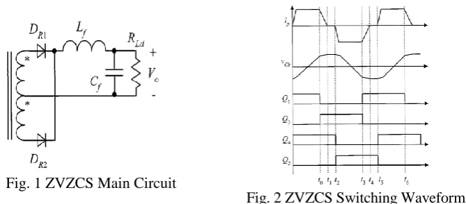
4. NOVEL ZVZCS PWMFB CONVERTER
4.1. Current Reset Strategies
In order to make the primary current decay to zero in zero state, a blocking voltage source can be inserted in series
with the primary winding. In zero state, if flows in the positive direction, the blocking voltage source is positive and
if flows in the negative direction, the blocking voltage source is negative. The blocking voltage source can be
simply realized by a capacitor , named a blocking capacitor. When conduct, charges . And
when conduct discharges . During zero state, the voltage of keepsconstantand resets shown
Fig. 1 ZVZCS Main Circuit
Fig. 2 ZVZCS Switching Waveforms
In zero state, the blocking capacitor has been fully discharged, so when the lagging leg turns on, the primary current
has an excess high current spike due to charging of the blocking capacitor. The larger the blocking capacitor, the
larger the current spike. When the leading leg turns off, the rectified voltage ramps down. As it becomes lower than
the blocking capacitor voltage, the blocking capacitor will supply the rectified output filter inductor current.
4.2 Comparison of the ZVZCS PWMFB Converters:
The converter is very simple because only one saturable inductor is needed. However, the use of the saturable
inductor results in two drawbacks. First, it causes a secondary duty cycle loss. In general, as the input voltage has a
certain variation range should be designed according to to prevent from saturation during zero state;
thus, the effective secondary duty cycle is reduced as decreases. The lower the the larger the secondary duty
cycle loss. Second, the saturable inductor causes high core loss since it saturates in both directions. The blocking
capacitor is shifted to the secondary side and an active switch is introduced, which cannot only reset the primary
current, but also clamp the rectified voltage to depress the parasitic voltage oscillation. However, the converter
requires an additional active switch and the associated control circuitry. The energy stored in the blocking capacitor is
delivered to the load during zero state. The converter is better than the other two in terms of simplicity.
5. PROPOSED METHOD
5.1 Introduction of RCFM pwm technique
Random Carrier Frequency Modulation techniques dither the switching period with a small amplitude variation
around the nominal value, so that the harmonic power is redistributed over the spectrum of concern. From Figure 4
where a PWM signal is generated from a continuous time input signal. Added random number is obtained by
applying a uniformly generated random number to a suitable mapping function. If the saw-tooth peak value is
constant, then slope is proportional to frequency, resulting in a Carrier Frequency Modulated PWM signal. In this
approach duty cycle is preserved. This is critical in closed loop applications since loop dynamics such as gain and
Fig: 3 Randomized PWM Generation Scheme Fig: 4. CSFPWM
6.
PROPOSED BLOCK DIAGRAM
Fig: 5. Proposed block diagram
The Zero-voltage switching (ZVS) phase shift modulated full bridge (PSM-FB) DC/DC converter with MOSFET
switches has been proposed in fig 6. Low component count and zero full load switching losses enable this topology
to achieve low cost, high power density, high efficiency, and low EMI, so for medium to high power DC/DC
applications it is a good choice.
Fig: 6. Simulink schematic of RPWM drive in IM drive
6.1. Full bridge dc-dc Converter
Two switches turn ON and OFF at the same time; the primary leakage inductor current will freewheel through the
body diodes to zero after the switches turn OFF, therefore no circulating current. Before the turn ON instant,
because four switches are all OFF, the turn ON voltage is half the input voltage. For case 2, after energy transfer
Q2 and the body diodes of Q3 or Q4, causing additional conduction losses. For case3, switchesQ3 and Q4 are
complimentary turned ON and OFF; after the energy transfer interval, primary side leakage inductor current will
first circulate through upper (Q1, Q3) switches and then circulate through lower (Q2, Q4) switches vice versa. This
depends on the current direction and next period PRBSG value.
6.2. PRBS Generator
A binary sequence (BS) is a sequence of bits, i.e.
for . A BS consists of ones and zeros.
A BS is a pseudo-random binary sequence (PRBS) if its autocorrelation function:
Have only two values:
Where
Is called the duty cycle of the PRBS, similar to the duty cycle of a continuous time signal.
7. RESULTS AND DISCUSSION
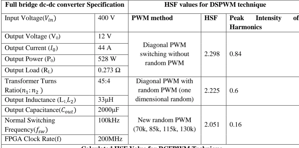
The simulation study is performed in MATLAB/Simulink software. A full bridge dc-dc converter is considered. The complete specification of the full bridge dc-dc converter is given in Table 1. The input dc voltage (Vin) is 400V and the switching frequency (𝑓 𝑤)of DSPWM is 100kHz.
Table 1.Converter Specification, HSF values for DSPWM technique and Calculated HSF Value for RCFPWM Technique
Full bridge dc-dc converter Specification HSF values for DSPWM technique
Input Voltage( ) 400 V PWM method HSF Peak Intensity of
Harmonics
Output Voltage (V0) 12 V
Diagonal PWM switching without
random PWM
2.298 0.84 Output Current ( ) 44 A
Output Power (P0) 528 W
Output Load (RL) 0.273 Ω
Transformer Turns Ratio( )
45:4 Diagonal PWM with random PWM (one dimensional random)
2.225 0.6 Output Inductance (L1, ) 33μH
Output Capacitance( ) 2000μF
New random PWM
(70k, 85k, 115k, 130k) 2.051 0.16 Normal Switching
Frequency(𝑓 𝑤)
100kHz
PWM Technique HSF Value
Random Carrier Frequency Modulation Technique 0.1105
Fig: 6. MATLAB- Simulink Model of Full bridge dc-dc Converter
The measured harmonic spread factors for diagonal switching with and without random are shown in Table 1.
Fig: 7. Calculated PSD for Diagonal PWM Technique with 80, 90kHz
Fig: 8. Calculated PSD for RCFM PWM Technique
Voltage across the point a and b can be shown in fig 9.and FFT analysis on figure 9
8. CONCLUSION
The converters are controlled by a diagonal switching frequency pulse width modulation technique that results in
significant harmonic intensity at the switching frequency. Random PWM is widely used to spread the harmonic
power, and hence reduce the torque ripples and acoustic noises of the ASDs. A comprehensive comparison of
DSPWM and Pseudo Random Binary Sequence (PRBS) bit based RPWM is presented in this chapter. The
distribution of harmonic power in the output voltage of full bridge dc-dc converter when controlled using DSPWM
is studied for three-phase star connected resistive load. A comparative analysis of SPWM and RPWM methods
characteristics such as DC bus utilization and the harmonic spread factor is presented. The proposed architecture of
RCPWM is the effective solution for the acoustic noise in the Adjustable Speed Drives. The results such as device
utilization summary, power estimation and temperature dependency are very useful for the handling of digital
device used for the control purpose. The harmonic power spreading ability of the RPWM is validated by the
simulation study .The RCPWM offers higher output voltage, lesser THD and minimal HSF than the DSPWM for
the entire working range.
REFERENCES
[1] Young-Cheol Lim, Seog-Oh Wi, Jong-Nam Kim and Young-Gook Jung, “A Pseudorandom Carrier Modulation
Scheme” IEEE Transactions on Power Electronics, Volume: 25 Issue: 4. pp. 797-804 April 2010.
[2] Akhil A. Balakrishnan, V. Shijoh, and T. Jarin “Phase Shift Controlled Full Bridge DC-DC Converter with Less
Circulating Loss” Middle-East Journal of Scientific Research, Volume 25, Issue 1, pp.: 65-73, 2017.
[3] T. Jarin and P. Subburaj “Comprehensive investigation on harmonic spreading effects of SPWM and RPWM
methods”, European Journal of Scientific Research ISSN 1450-216X / 1450-202X Vol. 103 No 2, pp.296 – 303,
June 2013.
[4] Hamid Khan, El-Hadj Miliani, and Khalil El Khamlichi Drissi., “Discontinuous random space vector
modulation for electric drives: A digital approach,” IEEE Transactions on Power Electronics, Vol. 27, No. 12,
December 2012, pp. 4944-4951.
[5] Ki-Seon Kim, Young-Gook Jung, and Young-Cheol Lim, “A New Hybrid Random PWM Scheme”, IEEE
Transactions on Power Electronics, Vol. 24, No. 1, January 2009 pp. 192- 200.
[6] T. Jarin, P. Subburaj, and Shibu J.V. Bright “Performance Evaluation and Experimental Validation of Random
Pulse Position PWM for Industrial Drives,” African Journal of Basic & Applied Sciences, Volume 7, Issue 3, pp.:
137-146 2015.
[7] Michael M. Bech, Frede Blaabjerg and John K. Pedersen, “Random modulation techniques with fixed switching
[8] Yen-Shin Lai, Ye-Then Chang, and Bo-Yuan Chen, “Novel random-switching pwm technique with constant
sampling frequency and constant inductor average current for digitally controlled converter,” IEEE Transactions
On Industrial Electronics, Vol. 60, No. 8, August 2013.
[9] Jarin T and Subburaj P, “Behaviour of Non-deterministic PWM Methods and Influence of DC Link Fluctuation
in Harmonic Spreading Effect of VSI Output Voltage Spectrum” International Journal of Applied Engineering
Research, ISSN 0973-4562 Vol. 10 No.20 (2015)
[10] T. Jarin , P. Subburaj and Shibu J V Bright “A ripple rejection inherited RPWM for VSI working with
fluctuating DC link voltage” Journal of Electrical Engineering & Technology, Volume 10, Issue 5, pp.: 2018-2030,
2015.
[11] T. Jarin and X. Z. Gao. “FPGA Based Analysis of Non-Deterministic PWM in Induction Motor Drives” Asian
Journal of Applied Science and Technology (AJAST) Volume 1, Issue 8, Pages 56-60, September 2017.
[12] S. Sheeba Rani Gnanamalar, Jarin T, S.S.Sreeja Mole, “Unique PWM cast for Induction Motor Drives with
Embracing Non-Deterministic Characteristics and Evaluation Using FPGA”, International Journal of Pure and