Abstract—In this paper some structural solution for human legs motion assistance and rehabilitations exoskeletons are presented. These solutions are used to develop virtual prototype for exoskeletons model, in order to build an optimized kinematic and dynamic model. The virtual prototype motion is analyzed using ADAMS multibody dynamics software. The exoskeletons motion is studied in two conditions, when it’s performs motion connected to a fixed supporting base and when it’s performs motion on the ground. The exoskeletons motion capabilities are analyzed and compared with normal human gait reference parameters. To obtain human motion gait parameters an experimental analysis is performed. The proposed solutions are original ones with easy operation features, low cost and easy implementation.
Index Terms—Exoskeleton design, motion analysis, human gait, leg mechanism.
I. INTRODUCTION
URRENTRLY, the subject of human motion assistance and rehabilitation is present in a large number of studies [1], [2], [3], [4], [5].
In order to recover the motor functions of the human lower limb, numerous passive or active solutions are known. Active recovery systems include exoskeleton-type locomotion devices. The exoskeleton is a system that helps the patient to walk and thus recover as much locomotion as possible. This is accomplished by providing an extra force to the human foot to which it is attached.
An exoskeleton robot provides active, programmable and controllable therapeutic assistance to patients with neuromotor deficiencies. Research in the field of exoskeletons robots has spread over the last decade. Progress in hardware and energy sources has enabled technically viable prototypes. In recent years, exoskeletons capable of reproducing human walking began to gain increased popularity in the United States for both locomotive assistance and rehabilitation. For example, the REX exoskeleton, produced by REX Bionics, is capable of providing locomotor recovery assistance to patients [2].
Manuscript received March 24, 2018; revised 05 April, 2018. This work is supported by PN-III 239PED from 01/09/2017 grant of the Executive Agency for Higher Education, Research, Development and Innovation Funding (UEFISCDI).
I. Geonea is with Faculty of Mechanics, University of Craiova. Calea Bucuresti Street no. 107. Romania (e-mail: [email protected]).
N. Dumitru is with Faculty of Mechanics, Univ. of Craiova. Calea Bucuresti Street no. 107. Romania (e-mail: [email protected]).
P. Rinderu is with Faculty of Mechanics, University of Craiova. Calea Bucuresti Street no. 107. Romania (e-mail: [email protected]).
A. Margine is with Faculty of Mechanics, University of Craiova. Calea Bucuresti Street no. 107. Romania (e-mail: [email protected]).
The features of exoskeleton systems and their obvious utility as active walking support systems are highlighted for Rewalk ™, Mina, Indego®, Ekso ™ systems and Rex® ReWalk ™, Indego® and Mina (lower limb exoskeleton) are effective for walking in clinical laboratory conditions [3].
In the field of medical recovery, the locomotors recovery is required for patients who have had strokes or spinal cord injuries in order to be able to practice walking again. The first research in this area, of motor exoskeleton systems, dates from 1960, and the initiative returns to two separate groups of researchers, one from the US and one from the former Yugoslavia [4]. The first group aimed at developing a technology to improve the abilities of the human carrier body, often for military purposes, while the second group attempted to develop a technology for assisting people with disabilities.
Currently the subject of human motion assistance and rehabilitation exoskeleton design is presented in a large number of papers, as presented in [7-11]. For disabled people’s motion assistance exoskeleton systems are developed by numerous research centers, which can assist the rehabilitation therapy [10]. Significant existing systems are discussed in: Chen, (2016) [1]; Anama et. al (2012) [2]; Diaz (2011) [3]; Yan (2015) [4]; Dumitru (2015) [23]; Geonea (2015) [6], with a large number of design solutions. But an important task of these systems is represented by the cost and easy operation feature and also easy implementation in practice [18-23].
The vast majority of exoskeleton solutions use one actuator motor for each leg joint. The originality of the proposed solutions consists in design of mechanical systems with a single degree of mobility, for which only one drive motor is required, according to Figs. 1-6.
In this paper are presented three design solutions for human motion assistance and rehabilitation exoskeletons.
II. STRUCTURAL AND DESIGN SOLUTION FOR LEG EXOSKELETONS
A. Exoskeleton first proposed structural solution
An exoskeleton is defined as an external powered device used to assist human motion. The first structural solution is presented in previous research papers [6-10]. The kinematic scheme of this proposed exoskeleton leg is presented in Fig. 1. This solution is an original one, developed by the first author of this paper, in the year 2013, in paper [9]. Also the second and third solutions for exoskeletons legs are original, developed in the year 2017.
Design Solutions for Human Legs Motion
Assistance Exoskeletons
Ionut Daniel Geonea, Nicolae Dumitru, Paul Rinderu and Alexandru Margine,
Member, IAENG
C
D
E
F
G A
K
L
J
H
I
M
l
4l
FGl
GHl
JKl
ILl
8
l
FGl
IMl
6 [image:2.595.307.530.47.232.2]
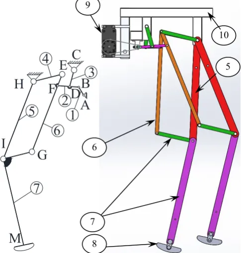
Fig. 1. Exoskeleton leg kinematic scheme and design solution.
[image:2.595.54.290.48.345.2]Thus, in Fig. 2, a general view of the exoskeleton for assisting the locomotion is presented, having the structure of the kinematic chains of the left and the right leg made by the mechanisms of bars with a single degree of mobility. The kinematic scheme of the bar mechanism used for the legs is shown in Fig. 1. The system provides the three anatomical flexion-extension movements for the hip, knee and ankle joints. The movement is transmitted from the drive motor 13 mounted on the upper support frame 18 by transmission with the chain wheels 14 and 15 of the shaft 19 which is supported at the ends in the bearings on the upper frame 12. The drive elements 1 of the leg mechanism with bars, are rigidly fixed to the motor shaft 19 in diametrically opposed positions to ensure the succession of the steps of the two legs of the exoskeleton. The C and G couplings of the bar mechanism are rotatable couplings with the base (top frame 12). By moving the two driving elements of each mechanism (corresponding to the two legs), the elements 5 and 9 of the mechanism perform a determined (unique) motion that reproduces the movement of the femur and tibia, as well as the motion law for the angle of joints G and I (hip and knee). For stepping on the ground, the exoskeleton is provided with a foot support 11. The articulation of the supports 11 with the element 9 is accomplished by mounting on the spindle axis M a torsion spring having an end with the foot 11 and the other end connected with the tibia element 9.
Fig. 2. Exoskeleton first proposed design solution (isometric view).
B. Exoskeleton second structural solution
Another exoskeleton solution for assisting human lower limb movement is shown in Fig. 3. It is characterized by the fact that it consists of two mechanisms, each of them consists of seven movable cinematic elements (1, 2, 3…7) of the bar type with parallelepiped section, articulated between them with rotating joints materialized by means of the pins 12. The motor elements of the two corresponding right and left foot mechanisms are actuated by the electric motor 9 which transmits the movement through two chain wheels a) and b) and the chain, to the shaft (11) which is mounted on the upper frame (12) by the bearings (A).
The solution is characterized in that it uses a single drive motor (9) provided with a gear box, transmitting the movement through the shaft (11) to the motor elements (1) of the two mechanisms for the left and right legs. The elements (1) are being mounted offset at 180 degrees on the shaft (11). Also, the exoskeleton is provided with a plastic piece on which a textile material for protecting the patient's back is fastened by gluing.
7
3
1
2
6
5
4
A
C
E
H
G
I
D
F
M
B
Fig.3. Kinematic scheme and prototype for the exoskeleton second solution.
2
1 4
5
59
7
8
39
5 10
6
7 8
[image:2.595.306.549.510.766.2]Fig.4. A virtual prototype (second solution), the isometric view.
C. Exoskeleton third structural solution
The kinematic scheme of the mechanism for the assistant's exoskeleton legs (third solution) is shown in Fig. 5. The proposed leg mechanism is composed by a parallelogram mechanism completed with a motor link for the mechanism. The links are noted with numbers from (1) to (5) and the joints with letters. The motor link of the mechanism is denoted with (1). The link (3) represents the femur, the tibia link is (5), the joint D represents the hip joint, and the knee joint is denoted with E. The size of the links (3) and (5) can be adjusted so that the shape of the point M trajectory to be an ovoid one, as to human gait.
The exoskeleton consists of two mechanisms for the left and right legs. The legs are composed of 5 elements connected by 7 kinematic rotating joints. The electric motor with reducer (8), which is mounted on the upper frame (6), is used to drive the two mechanisms.
This leg mechanism can assure the mobility of knee and hip joints. The ankle joint is not considered because its angular amplitude during walking is small.
5
1
4
3
2 C
D
F
E
A
B
M
[image:3.595.51.288.541.767.2]
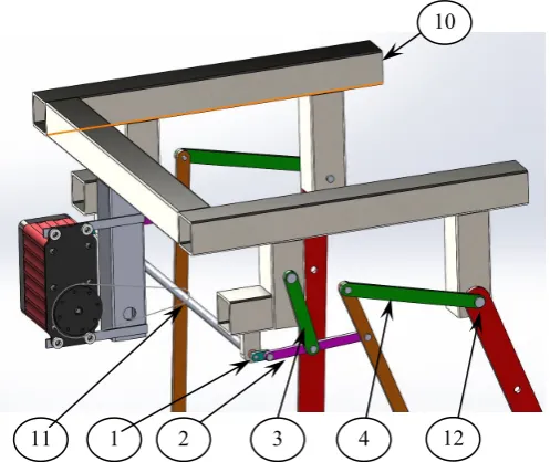
Fig. 5. A mechanical design of the third proposed exoskeleton.
Fig. 6. Aspects of mechanical design of the proposed exoskeleton.
III. HUMAN GAIT BIOMECHANICS ANALYSIS
Today exists on the market, a large number of equipment’s and software to study human gait. The human leg joints angular variations were analyzed for a healthy male of 1.65 m height, 68 kg, age 35 by using goniometers sensors on each joint, as in Fig. 7.
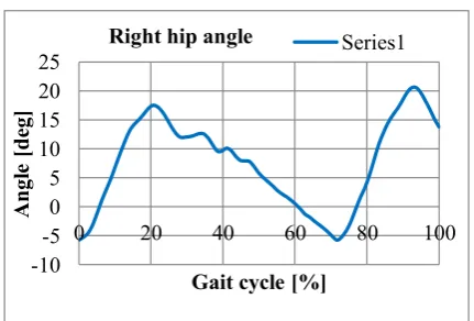
With the aid of Biometrics software, the angular variations of each joint were acquired and plotted, in Figs. 8-10, and analyzed by comparison with others obtained data for human gait from literature [12-16]. The obtained results are usual for normal gait. The knee angle amplitude reaches 70°, as is plotted in Fig. 9, and the hip joint angle amplitude reaches 35-40°, as is plotted in Fig. 10.
Fig. 7. Subject with wearable sensors and motion processing. 11
10
4 3
1 2
11
9 10
4
5 3
1 2
6
7
8
12
[image:3.595.312.542.617.744.2]-10 -5 0 5 10 15
0 20 40 60 80 100
An
gl
e
[d
eg
]
Gait cycle [%]
Right ankle angle Series1
-20 -10 0 10 20
0 20 40 60 80 100
A
ngle
[d
eg]
Gait cycle [%]
[image:4.595.308.549.51.196.2]Left ankle angle Series1
Fig. 8. Ankle joints angle variation in time.
-80 -60 -40 -20 0
0 20 40 60 80 100
An
gl
e
[d
eg
]
Gait cycle [%]
Right knee angle Series1
0 20 40 60 80
0 20 40 60 80 100
Angl
e
[d
eg]
Gait cycle [%]
[image:4.595.62.278.54.293.2]Left knee angle Series1
Fig. 9. Knee joints angle variation in time.
-10 -5 0 5 10 15 20 25
0 20 40 60 80 100
Angl
e
[d
eg]
Gait cycle [%]
Right hip angle Series1
-30 -20 -10 0 10 20
0 20 40 60 80 100
Angl
e
[d
eg]
Gait cycle [%]
Left hip angle Series1
Fig. 10. Hip joints angle variations in time.
IV. MODELING AND SIMULATION OF EXOSKELETONS MOTION
[image:4.595.49.288.326.612.2]A dynamic simulation has been developed by using a proper model for operation tests in ADAMS environment (ADAMS 2013). Contact, stiffness, damping coefficients, and friction force coefficients have been introduced in the ADAMS model accordingly, as listed in Fig. 14, with links made of steel.
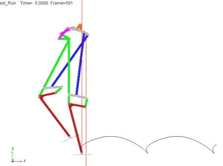
Fig. 11. Superimposed frames of the exoskeleton walking (first design).
Fig. 12. Superimposed frames of the exoskeleton walking (second design).
Fig. 13. Superimposed frames of the exoskeleton walking (third design).
[image:4.595.306.548.338.462.2] [image:4.595.61.277.634.780.2]design model are shown in Figs. 11, 12 and 13.
[image:5.595.46.289.69.346.2]Fig. 14. Adams dynamic model contact parameters.
Fig. 15. Knee joints angle variation in time, computed in ADAMS.
Fig. 16. Hip joints angle variation in time, computed in ADAMS.
[image:5.595.55.275.367.579.2]For the first design model, the knee joints angle variation in time is shown in Fig. 15, and hip joints angle variation in time are presented in Fig. 16.
[image:5.595.308.534.494.662.2]Fig. 17. Exoskeleton (first design) ADAMS computed foot path trajectory.
Fig. 18. Exoskeleton walking (first design) computed foot path trajectory.
[image:5.595.55.276.602.710.2]Fig. 19. Exoskeleton (second design) computed foot trajectory.
Fig. 20. Exoskeleton (third design) computed foot trajectory.
V. CONCLUSION
In this paper original design solutions for prototypes of motion assistance and rehabilitation exoskeletons of human are presented, with low cost and easy-operation features. The results obtained with ADAMS computational model indicate suitable performance for operation in walking rehabilitation application. The proposed design is simple, wearable and light with anthropomorphic structure. The proposed solutions operate with only one motor with controllable angular velocity. The exoskeletons design purpose is to fully or partially help and assist human walking and also to assure proper motions for gait rehabilitation.
ACKNOWLEDGMENT
This work is supported by PN-III 239PED from 01/09/2017 grant of the Executive Agency for Higher Education, Research, Development and Innovation Funding (UEFISCDI).
REFERENCES
[1] B. Chen, “Recent developments and challenges of lower extremity exoskeletons”, Journal of Orthopaedic Translation, 2016, 5: 26-37. [2] K. Anama, A.A. Al-Jumaily, “Active exoskeleton control systems:
state of the art”, Procedia Eng. 41, 988–994 (2012).
[3] I. Díaz, J.J. Gil, E. Sánchez, “Lower-limb robotic rehabilitation: literature review and chal-lenges”, J. Robot. (2011).
[4] T. Yan, et al., “Review of assistive strategies in powered lower-limb orthoses and exoskeletons”, Robotics and Autonomous Systems, 2015, 64: 120-136.
[5] W. Huo, et al., “Lower limb wearable robots for assistance and rehabilitation: A state of the art”, IEEE systems Journal, 2016, 10.3: 1068-1081.
[6] I. Geonea, M. Ceccarelli, G. Carbone, “Design and Analysis of an Exoskeleton for People with Motor Disabilities” The 14th IFToMM World Congress, Taipei, Taiwan, 2015.
[7] Geonea, I. D. and Tarnita, D., “Design and evaluation of a new exoskeleton for gait rehabilitation”, Mech. Sci., 8, 307-321, https://doi.org/10.5194/ms-8-307-2017, 2017.
[8] I. Geonea, M. Ceccarelli, C. Copilusi, “New Assistive Device for People with Motor Disabilities”, Applied Mechanics and Materials, Vol. 772, pp. 574-579, 2015.
[9] I. D. Geonea, et al., “Design and Simulation of a Single DOF Human-Like Leg Mechanism”, Applied Mechanics and Materials, Vol. 332, pp. 491-496, (2013).
[10] I. Geonea, N. Dumitru, A. Rosca, A. Petcu, L. Ciurezu, “Experimental Validation of an Exoskeleton for Motion Assistance”, Applied Mechanics and Materials, Vol. 880, pp. 111, 2018.
[11] Tarnita, Daniela, Ionut Geonea, and Alin Petcu, “Experimental Human Walking and Virtual Simulation of Rehabilitation on Plane and Inclined Treadmill”, Acoustics and Vibration of Mechanical Structures-AVMS-2017, Springer, Cham, 2018, pp.149-155. [12] Tarnita, D., Geonea, I., Petcu, A., & Tarnita, D. N., “Numerical
Simulations and Experimental Human Gait Analysis Using Wearable Sensors”, In International Workshop on Medical and Service Robots (pp. 289-304), Springer, Cham, 2016.
[13] D. Tarnita, “Wearable sensors used for human gait analysis”, Rom J MorpholEmbryol 57(2), pp.373-382, (2016).
[14] Tarniţă, D., Geonea, I., Petcu, A., & Tarniţă, D. N, “Experimental characterization of human walking on stairs applied to humanoid dynamics”, In International Conference on Robotics in Alpe-Adria Danube Region, (pp. 293-301), Springer, Cham, (2016, June). [15] Margine, A., Ungureanu, A., Rinderu, P., & Dima, A. (2017),
“Numerical Simulation and Experimental Characterization of a Leg Exoskeleton for Motion Assistance”, In Proceedings of the World Congress on Engineering (Vol. 2). Available:
http://www.iaeng.org/publication/WCE2017/WCE2017_pp1013-1018.pdf
[16] Tarniţă, D., Calafeteanu, D. M., Geonea, I. D., Petcu, A., & Tarniţă, D. N. (2017), “Effects of malalignment angle on the contact stress of knee prosthesis components, using finite element method”, Romanian journal of morphology and embryology, 58(3), 831-836.
[17] Meng, L., Ceccarelli, M., Yu, Z., Chen, X., and Huang, Q., “An experimental characterization of human falling down”, Mech. Sci., 8, 79–89, https://doi.org/10.5194/ms-8-79-2017, 2017.
[18] Zhang, J., Yi, X., Wang, J., & Chen, W., “Structure design and simulation on bionic lower extremity rehabilitation robot”, In Industrial Electronics and Applications (ICIEA), 2017 12th IEEE Conference on (pp. 1304-1309), IEEE, 2017
[19] Bethoux, F., Varsanik, J. S., Chevalier, T. W., Halpern, E. F., Stough, D., & Kimmel, Z. M. (2018), “Walking speed measurement with an Ambient Measurement System (AMS) in patients with multiple sclerosis and walking impairment”, Gait & posture, 61, 393-397. [20] Huysamen, K., de Looze, M., Bosch, T., Ortiz, J., Toxiri, S., &
O'Sullivan, L. W. (2018), “Assessment of an active industrial exoskeleton to aid dynamic lifting and lowering manual handling tasks” Applied Ergonomics, 68, 125-131.
[21] Mohanta, J. K., Mohan, S., Deepasundar, P., & Kiruba-Shankar, R. (2017), “Development and control of a new sitting-type lower limb rehabilitation robot”, Computers & Electrical Engineering.
[22] Wang, M., & Ceccarelli, M. (2015), “Topology search of 3-DOF translational parallel manipulators with three identical limbs for leg mechanisms”, Chinese Journal of Mechanical Engineering, 28(4), 666-675.
[image:6.595.56.254.298.507.2]