BOSS/IX Diagnostics and
Error Log Manual
July, 1989
M6204C
Section
Cover Title Page Page Status Table of Contents
List of Figures List of Tables Preface Section 1 Section 2 Section 3 Section 4 Section 5 Section 6 Section 7 Section 8 Section 9 Section 10 Appendix A
PAGE STATUS
Pages STATUS-1CONTENTS-1 thru -11 CONTENTS-12
CONTENTS-12 PREFACE-1 1-1 thru 1-4 2-1 thru2-32 3-1 thru 3-28 4-1 thru 4-12 5-1 thru 5-12 6-1 thru 6-151 7-1 thru 7-91 . 8-1 thru 8-76 9-1 thru 9-16
10-1 thru 10-10 A-1 thru A-5
TABLE OF CONTENTS
Page
Section 1 - Introduction
1. 1 Overv-iew •.••••••••••••••••••••.•••.•••••••••••••.•••••.••••••••••••.•••••••••••••••••••••••••••••••••••••••••.•.•..•••.•.. 1-1
1.2
Diagnostic
Strategy ...
1-1
1.3
Related Publications •••••••.•••••••••••••••••••••••••••••••••••••••.•••••••••••••••••..•.•••••••.•••••••••.••.••.... 1-2
1.4 Notational Conventions ••••.••••...•••...••.•.••••••••••.•••••••••....•.•..•...••.•....•..•...•.. 1-3 1.4.1 Keys and Key Sequences ... 1-3 1.4.2 Entered and Displayed Information ... 1-3 1.4.3 Command Format Descriptions ... 1-4
1.5
Abbreviations ...•...•...•... 1-4
Section 2 - Error Logging
2.1 2.2 2.2.1 2.2.2
2.3
2.3.1 2.3.1.1 2.3.1.2 2.3.1.3 2.3.1.4 2.3.1.5 2.3.1.6 2.3.1.7 2.3.1.8 2.3.2 2.3.3 2.3.4 2.3.5 2.3.6 2.3.7 2.3.8 2.3.9<:)"Itr1filtlftf •••••• ~ ••••••••••••••••••••••••••••••••••••••••••••••••••••••••••••••••••••••••••••••••••••••••••••••••••••••••••• ~-1 The Error Log Command ..•....•...•...•••.••...•..•..••••...•.•....•.•... 2-1
Displaying the Error Log ... 2-2 The Error Log Display ... 2-2
E:r1r()r
Il1terllrl!t2lti()I1 •••••••••••••••••••••••••••••.•••••••••••••••••••••••••••••••••••••••••••••••...•.•.••...•...
:!-:J System Trap Errors ... 2-4 Bus Error. Memory Manager and Odd Address ... 2-5 Miscellaneous Traps ... 2-7 Parity Error (MAl 2000 only) ... 2-8 Single and Multiple Bit Memory Errors (MAl 2500/3000/4000 only) ... 2-9 Data Cache Parity (MAl 2500/3000/4000 only) ... 2-11 Calendar (MAl 2500/3000/4000 only) ... 2-12 UPS Transition (MAl 2500/3000/40eO only) (MAl 3000/4000 only) ... 2-13 Expansion Interface Transmission Errors (MAl 3000/4000 only) ... 2-14 1/2 Inch Streamer ... ~ ... 2-15 Cartridge Tape ... 2-18 Floppy Disk (MAl 2000 only) ... 2-20 Printer Filter (Printer) ... 2-22 ·CMB ... 2-24 Four and Eight Way Boards ... 2-25 LAN ... 2-27 Winchester Disk ... 2-28Section 3 - Basic All-Purpose Service System (BASS)
3.1
3.2
3.2.1 3.2.23.3
3.3.1 3.3.2 3.3.3 M6204CIlltr()cillc:ti()r1 •••••••••••••••••••••••••••••••••••••••••••••••••••••••••••••••••••••••••••••••••••••.••••••••••••••••••••.••• :1-1
!))ftstE!r11 RE!'1tJirl!rI1E!l1tss •••••••••••••••••••••••••••••••••••••••••••••••••••••••••••••••••••••••••••••••••••••••••••••• :J-1
Hardware Requirements ... 3-1 Software Requirements ... 3-1
FllIl1l1il1S1 ElA!)!) ••••••••••••••••••••••••••••••••••••••••••••••••••••••••••••••••••••••••••••••••••••••••••••••••••••••••• :l-:!
Starting BASS ... 3-2 BASS Testing Options ... 3-3 Test Result Summary Screen ... 3-3
Section 3 - Basic All-Purpose Service System (BASS)
(cont'd) 3.3.4 3.3.5 3.3.63.4
3.4.1 3.4.1.1 3.4.1.2 3.4.1.3 3.4.1.4 3.4.2 3.4.2.1 3.4.2.2 3.4.2.3 3.4.2.4 3.4.2.5 3.4.2.6 3.4.3 3.4.3.1 3.4.3.2 3.4.3.3 3.4.3.4 3.4.3.4.1 3.4.3'.4.2 3.4.3.4.3 3.4.3.4.4 3.4.3.4.5 3.4.3.4.6 3.4.3.4.7 3.4.3.4.8 3.4.3.4.9 3.4.3.4.10 3.4.3.4.11 3.4.3.4.12 3.4.3.4.13 3.4.3.4.14 3.4.3.4.15 3.4.4 3.4.4.1 3.4.4.2 3.4.4.2.1 3.4.4.2.2 3.4.4.2.3 3.4.4.2.4 3.4.4.2.5 CQf.jTENTS-2B /4 Service System Procedure ... 3-4
Inspection and Bum-In Cycle Procedures ... 3-5
Print/Display Previous Test Results ...
3-7El~!)!)
Tttsrt
[)ttlSc:rillti()I1It ••••••••••••••••••••••••••••••••••••••••••••••••••••••••••••••••••••••••••••••••••••••••••• :J-~Disk Device Tests ...
3-9Disk Dump Test ...
3-10Direct File Exerciser ... "
...
3-10File Integrity Test ...
3-11Freespace Analysis and File System Check Test ...
3-11Magnetic Cartridge Streamer Exerciser ...
3-12.MCS Label Test ...
3-13MCS Save Test ...
3-13MCS Ust Test ...
3-13MCS Compare Test ...
3-13MCS Restore Test ...
3-13Additional Bum-In Cycle Testing ...
3-14Printer Exerciser ...
3-14Printer Quality Test ...
3-14Print Quality Check Test. ...
3-15Printer Ripple Test ...
3-15Printer Function Test ...
3-16Ripple Pattern Test ...
3-17Line Width Density Test ...
3-17Une Height Density Test ...
3-17Underline Test ...
3-17Carriage Positioning Test ...
3-17Expanded Ripple Pattern Test.. ...
3-17New Une Test ... " ...
3-18Overprint Test. ...
3-18Plot Mocte Test ...
3-18Ring Bell Test ...
3-18Bold Print Test ...
3-18Load/Test VFU Test ...
3-19Super/Subscript Test ...
3-19Bin Sheet Feed Test ...
3-19Worst Case Pattern Test ...
3-19Terminal Exerciser ...
3-20Run Instructions ...
3-20Test Descriptions ...
3-21TABLE OF CONTENTS
Page
Section 3 - Basic All-Purpose Service System (BASS)
(cont'd)3.4.5 3.4.5.1 3.4.5.2 3.4.5.3 3.4.5.3.1 3.4.5.3.2 3.4.5.3.3 3.4.5.3.4 3.4.5.3.5 3.4.5.3.6 3.4.6 3.4.6.1 3.4.6.2 3.4.6.3 3.4.6.4 3.4.6.5 3.4.6.6
LAN Exerciser... 3-24 Additional Setup Requirements ... 3-25 Run Instructions ... 3-25 Test Descriptions ... 3-25 LAN Initialization (L01 ): ... 3-25 LAN Who's There Test (L02) ... 3-25 LAN Network Test (L03) ... 3-26 Remote LAN Who's There Test (L04) ... 3-26 Remote LAN Network Test (L05) ... 3-26 Expected LAN Topography MAP Editor (L06) ... 3-26 Magnetic Tape Streamer Exerciser ... 3-26 MTS Label Test ... 3-27 MTS Save Test ... 3-27 MTS Ust Test ... ; ... 3-28 MTS Compare Test ... 3-28 MTS Restore Test ... 3-28 Additional Bum-In Cycle Testing ... 3-28
Section 4 - Diagnostic Executive
~. 1 t:)"E!"'it!~ ••••••••••••••••••••••••••••••••••••••••••••••••••••••••••••••••••••••••••••••••••••••••••••••••••••••••••.•••..•. lJ-1 ~.:! I.CJtIci [)iIlSlI1()lItiC: E:lCE!c:lJti"t! •••••••••••••••••••••••••••••••••••••••••••••••••••••••••••••••••••••••••••••.•••••••• LJ-1
~.:I . E:l(t!c:lJti"l! c:()l11l11l1l1cill ••••••••••••••••••••••••••••••••••••••••••••••••••••••••••••••••••••••••••••••••••••••••••••••• ~:I
4.3.1 Executing Commands ... 4-3 4.3.2 Command Descriptions ... 4-3 4.4 Error Reporting •••••••••••••••••••••••••••••••••••••••••.••••••.•••••••••••..••••••••.••.••••••••••...••.•...••...•... 4-11 4.4.1 Error Codes ... 4-11 4.4.2 Disk Error Messages ... 4-11 4.4.3 Tape Error Messages ... 4-12 4.4.4 Other Error Messages ... 4-12
Section 5 - System Interaction Test
5.1
5.1.1.5.2
5.2.1 5.2.25.3
5.3.1 5.3.2 5.3.3 5.3.4 M6204C:4:)"E!",il!lftt •••••••••••••••••••••••••••••••••••••••••••••••••••••••••••••••••••••••••••••••••••••••••••••••••••••••••••••••••• !t-1
When to Use SIT ... 5-1 !)Ilr C:()l1fiSlllrllti()11 FlEtCltJirEtI11E!l1tll ••••••••••••••••••••••••••••••••••••••••••••••••••••••••••••••••••••••••••••• !i-:!
Hardware Requirements ... 5-2 Software Requirements .... ' ... 5-2
!)~rtil1S1 I1l1ci FlIJI111il1S1 !»Ilr ••••••••••••••••••••••••••••••••••••••••••••••••••••••••••••••••••••••••••••••••••••••••• !i-:! Load Diagnostic Executive ... 5-2 Start Printer Output ... 5-3 Load ing SIT ... 5-3 Using SIT Commands ... ~ ... 5-4
Section 5 - System Interaction Test
(cont'd)5.4
5.4.1
5.4.2
5.4.3
5.4.4
5.4.5
5.4.6
5.4.7
5.4.8
5.4.9
5.4.10
5.5
5.5.1
5.5.2
!)Ilr lrllllit 1lt!!Sc:riJ)ti()1111 •••••••••••••••••••••••••••••••••••••••••••••••••••••••••••••••••••••••••••••••••••••••••••••• !i-!i
LAN Task ... 5-5
Four-way Task ...
~... 5-5
Eight-way Task ... 5-5
MCS Task ... 5-5
MTS Task ...
5-6 FloppyDrive Task ....•...
5-6Winchester Disk task ...
5-6Memory Task ...
5-6Floating Point Task ...
5-6Serial Communications Controller Task ... 5-7
!)Ilr c:()rt1l1lllrlciSl ••••••••••••••••••••••••••••••••••••••••••••••••••••••••••••••••••••••••••••••••••••••••••••••••••••••••• !t-47
Basic Commands ...
~... 5-7
Advanced Commands ... 5-9
Section 6 - Logic Tests
6.1 6.2
6.2.1
6.2.2
6.2.3
6.2.3.1
6.2.3.2
6.2.3.3
6.2.3.4
6.2.3.5
6.2.3.6
6.3
6.3.1
6.3.1.1
6.3.1.2
6.3.1.3
6.3.1.4
6.3.1.5
6.3.2
6.3.2.1
6.3.2.2
6.3.2.3
6.3.2.4
6.3.3
6.3.3.1
6.3.3.2
6.3.3.3
6.3.3.4
C:ON1"EN1r!)-4«:)"t!",il!~ ••••••••••••••••••••••••••••••••••••••••••••••••••••••••••••••••••••••••••••••••••••••••••••••••••••••••••••••••••• E)-1
C3i1t11t!11I1 FllIl1 fJr()c:l!CitJrl!lI •••••••••••••••••••••••••••••••••••••••••••••••••••••••••••••••••••••••••••••••••••••••••• E)-1
Load Diagnostic Executive ... 6-1
Start Printer Output ... 6-2
Running
theLogic Tests ...
6-2Run Logic Tests in Auto Mcx:le ... 6-2
Running Individual Logic Tests ... ; ... 6-3
Selecting and Running Subtests ... 6-5
Shutdown From Diagnostics Executive ... 6-5
Executive Commands for Logic Tests ... 6-5
Manual Intervention Tests ... 6-7
I.CJtIiC: lrltllt 1lt!1Ic:r1lJti()1111 ••••••••••••••••••••••••••••••••••••••••••••••••••••••••••••••••••••••••••••••••••••••••••• E>-IJ
Winchester Disk Logic Test ... 6-8
Loading and Running the Winchester Logic Test ... 6-8
Winchester Subsystem Test Descriptions ... 6-9
Winchester Test Commands ... 6-19
Command Macros ...
~... 6-25
ErrorDescriptions ...
6-26MCS Logic Test ...
6-31Loading and Running the MCS Logic Test ... 6-31
MCS Test Descriptions ... 6-31
MCS Logic Test Commands ... 6-35
MCS Logic Test Error Messages ... 6-36
MTS Logic Test ... 6-3 7
Loading and Running the MTS Logic Test ... 6-37
MTS Test Descriptions ... 6-37
MTS Logic Test Commands ...
~... 6-43
Error Messages ... 6-44
TABLE OF CONTENTS
Page
Section 6 - Logic Tests
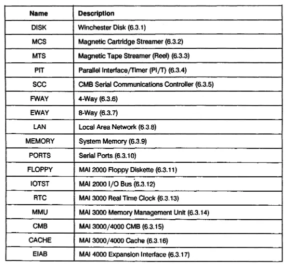
(cont'd)6.3.4 6.3.4.1 6.3.4.2 6.3.4.3 6.3.4.4 6.3.4.5 6.3.5 6.3.5.1 6.3.5.2 6.3.5.3 6.3.5.4 6.3.5.5 6.3.5.6 6.3.6 6.3.6.1 6.3.6.2 6.3.6.3 6.3.6.4 6.3.6.4 6.3.6.5 6.3.7 6.3.7.1 6.3.7.2 6.3.7.3 6.3.8 6.3.8.1 6.3.8.2 6.3.8.3 6.3.8.4 6.3.9 6.3.9.1 6.3.9.2 6.3.9.3 6.3.9.4 6.3.9.5 6.3.9.6 6.3.9.7 6.3.10 6.3.10.1 6.3.10.2 6.3.10.3 6.3.10.4 6.3.11 6.3.11.1 6.3.11.2 6.3.11.3 6.3.11.4 M6204C
Parallel Interface /Timer Logic Test ... 6-45 Loading and Running the PI
IT
Logic Test ... 6-45 PI/T Test Initialization ... 6-45 PI/T Test Descriptions ... 6-45 PI/T Logic Test Commands ... 6-48 Error Messages ... 6-48 SCC Logic Test ... 6-49 Special Hardware Requirements ... 6-49 Special Software Requirements ... 6-49 Loading and Running the SCC Logic Test ... 6-49 SCC Test Descriptions ... 6-50 SCC Logic Test Commands ... 6-52 Error Messages ... 6-52 Four-Way Logic Test ... 6-55 Loading and Running the 4-Way Logic Test ... 6-55 Test Initialization ... 6-55 4-Way Test Descriptions ... 6-56 Four-way Logic Test Commands ... 6-59 Error Messages ... 6-61 Error Message Headers ... 6-64 Eight-Way Logic Test ... 6-65 Loading and Running the 8-Way Logic Test ... 6-65 8-Way Test Descriptions ... 6-65 Eight-way Logic Test Commands ... 6-68 LAN Logic Test ... 6-70 Loading and Running the LAN Logic Test.. ... 6-70 LAN Test Descriptions ... 6-70 LAN Test Commands ... 6-73 Error Messages ... 6-75 Memory Logic Test ... 6-80 Loading and Running the Memory Logic Test ... 6-80 Memory Test Initialization ... 6-80 Memory Test Descriptions ... 6-81 Memory Test Commands ... 6-84 Building Command Files ... 6-86 Scope Loop Commands ... 6-87 Error Messages ... 6-88 Serial Ports Test ... 6-89 Loading and Running the Serial Ports Logic Test. ... 6-89 Serial Ports Test Description ... 6-89 Serial Ports Commands ... 6-89 Error Messages ... 6-90 MAl 2000 Floppy Logic Test ... 6-91 Loading and Running the Floppy Logic Test ... 6-91 Floppy Logic Test Descriptions ... 6-91 Floppy Test Commands ... 6-93 Error Messages ... 6-94Section 6 - Logic Tests
(cont'd)
6.3.12 6.3.12.2 6.3.12.3 6.3.12.4 6.3.12.5 6.3.13 6.3.13.1 6.3.13.2 6.3.13.3 6.3.13.4 6.3.13.5 6.3.14 6.3.14.1 6.3.14.2 6.3.14.3 6.3.14.4 6.3.14.5 6.3.15 6.3.15.1 6.3.15.2 6.3.15.3 6.3.15.4 6.3.16 6.3.16.1 6.3.16.2 6.3.16.3 6.3.16.4 6.3.16.5 6.3.16.6 6.3.17 6.3.17.1 6.3.17.2 6.3.17.3 6.3.17.4 6.3.17.5 6.3.18 6.3.18.1 6.3.18.2 6.3.18.3 6.3.18.4 6.3.18.5 CONTENTS-6MAl
2000B us Logic Test ...
6-95I/O Bus Test Descriptions ...
6-95EIEIO Function Commands ...
6-97Error Messages ...
6-98Error Message Headers ... 6-99
Real Time Clock Logic Test.. ...
6-100Loading and Running the RTC Logic Test ...
6-100RTC Test Initialization ...
6-100RTC Test Descriptions ...
6-100RTC Test Commands ...
6-1 01Error Messages ...
6-1 01Memory Management Unit Logic Test.. ...
6-102Loading and Running the MMU Logic Test.. ...
6-102MMU Test Initialization ...
6-102RTC Test Descriptions ...
6-1 02MMU Test Commands ...
6-106Error Messages ... : ...
6-1 06MAl
3000/4000CMB Logic Test ...
6-109Loading and Running the CMB Logic Test ...
6-109CM B Test Descriptions ...
6-1 09CMB Test Commands ...
6-111Error Messages ...
6-111CMB Cache Logic Test ...
6-112TABLE OF CONTENTS
Page
Section 7 - Function Select Tests
7.1 7.2 7.2.1 7.2.2
7.3
7.3.1 7.3.2 7.3.3 7.3.47.4
7.4.1 7.4.1.1 7.4.1.2 7.4.1.3 7.4.1.4 7.4.1.4.1 7.4.1.4.2 7.4.1.4.3 7.4.1.4.4 7.4.1.4.5 7.4.1.4.6 7.4.1.4.7 7.4.1.4.8 7.4.1.4.9 7.4.1.5 7.4.1.5.1 7.4.1.5.2 7.4.1.5.3 7.4.1.5.4 7.4.2 7.4.2.1 7.4.2.2 7.4.2.3 7.4.2.3.1 7.4.2.3.2 7.4.2.3.3 7.4.2.3.4 7.4.2.4 7.4.3 7.4.3.1 7.4.3.2 7.4.3.3 7.4.3.3.1 7.4.3.3.2 7.4.3.3.3 7.4.3.3.4M6204C
C:»"E!r1tiE!\ftt ••••••••••••••••••••••••••••••••••••••••••••••••••••••••••••••••••••••••••••••••••••••••••••••••••••••••••••••••••
~-1 General Run Procedures ... 7-1Load Diagnostic Executive ... ~ ... 7-1 Start Printer Output ... 7-2
LJllil1lJ F=lJllc:ti()11 !»E!IEtc:t
lrE!!it!l ••••••••••••••••••••••••••••••••••••••••••••••••••••••••••••••••••••••••••••••••••.•
4r-~ Enable Service Mode ... 7-2 Select Function Select Tests ... 7-2 Executing Commands ... 7-3 Building and Executing Test Loops ... 7-3i=lIllc:ti()r1 !)elec:t lresst [)essc:rif)ti()r1ss ••••••••••••••••••••••••••••••••••••••••••••••••••••••••••••••••••••••••••• 7-4
Winchester Disk Function Select Test.. ... 7-5 Test Requirements ... 7-5 Load ing the Test ... 7-5 Test Modes ... 7-6 Winchester Disk Function Select Commands ... 7-7 Standard Commands ... 7-7 Buffer Commands ... 7-9 Parameter Commands ... 7-11 Initialization Commands ... 7-14 Control Commands ... 7-15 Immediate Commands ... 7-17 Execute Commands ... 7-21 Multiple Parameter Execute Commands ... 7-22 High Level Commands ... 7-23 Error Reporting ... 7-25 Bad Status Before Command Issued ... 7-25 Bad Status After Command Issued ... 7-25 Interpretive Messages ... 7-28 Warning Messages ... 7-29 MCS Function Select Test ... 7-30 Test Requirements ... 7-30 Loading the Test ... 7-30 T est Command Descriptions ... 7-30 Programmed Output Commands ... 7-30 IOPB Commands ... 7-31 Customized Commands ... 7-33 Macro Commands ... 7-35 Error Reporting ... 7-36 MTS Function Select Test ... 7-37 Test Requirements ... 7-37 Loading the Test ... 7-37 Command Descriptions ... 7-37 Primitive Commands ... 7-37 SCSI Tape Adapter Commands ... 7-41 General SCSI Commands ... 7-42 Sequential SCSI Commands ... 7-42
Section 7 - Function Select Tests
(cont'd)
7.4.4 7.4.4.1 7.4.4.2 7.4.4.3 7.4.4.4 7.4.4.4.1 7.4.4.4.2 7.4.5 7.4.5.1 7.4.5.2 7.4.5.3 7.4.5.4 7.4.5.4.1 7.4.5.4.2 7.4.6 7.4.6.1 7.4.6.2 7.4.6.3 7.4.6.4 7.4.7 7.4.7.1 7.4.7.2 7.4.7.3 7.4.7.4 7.4.8 7.4.8.1 7.4.8.2 7.4.8.3Four-way Function Select Test. ...
7-45Test Requirements ...
7 -45Loading the Test ...
7-45 .Command Descriptions ...
7 -45Error Reporting ...
7 -49Error Messages ...
7-49Message Headers ...
7-51Eight-way Function Select Test.. ...
7 -53Test Requirements ...
7 -53Loading the Test ...
7-53Command Descriptions ...
7·-53Error Reporting ... 7
-58Error Messages ...
7-58Message Headers ...
7-60LAN Function Select Test ... ; ...
7 -62Test Requirements ...
7-62Load ing the Test ...•...
7-62Command Descriptions ...
7-62Error Reporting ...
7"-66
MAl
2000Roppy Function Select Test ...
7-67Test Requirements ... 7
-67Loading the Test ...
7-67Command Descriptions ...
7-67Error Messages ...
7-74Dual SCSI Controller Function Select Test ...
7-75Test Requirements ...
7-75Loading the Test ... 7
-75Command Descriptions ...
7-75Section 8 - Micro-Diagnostic System
8.1
8.2
8.2.1 8.2.28.2.3
8.2.4 8.2.5 8.2.68.3
8.3.1 8.3.2 8.3.3 8.3.4 8.3.58.4
C:ONTENT!;-8c:t"Etr1tiEt\ftt ••••••••••••••••••••••••••••••••••••••••••••••••••••••••••••••••••••••••••••••••••••••••••••••••••••••••••••••••••• 1J-1
IWI[)!)
c:tJ)l!l1Iti()I1 •••••••••••••••••••••••••••••••••••••••••••••••••••••••••••••••••••••••••••••••••••••••••••••••••••••••••1l-1
System Pre-tests ...
8-1System Sense Switches ...
8-3Self-Tests ... 8-5
Shutdown and Boot Prompt ...
8-6System Console Control ...
8-6Control Sequences ...
8-7IWI[)!)
Tlltst
lWI()(IlIlE! c:()rrtr()I ••••••••••••••••••••••••••••••••••••••••••••••••••••••••••••••••••••••••••••••••••••••••
~IIHel P Commands ...
8-8Module Selection Commands ...
8-9Test Selection Commands ...
8-10Test Option Commands ...
8-11Software Debugging Commands ...
8-13 <alt
>
Boot and Alternate Load Program M()(Iule ••••••••••••••••••••••••••••••••••••••••••••••••••••
~20TABLE OF CONTENTS
Page
Section 8 - Micro-Diagnostic System
(cont'd) 8.5 8.5.1 8.5.2 8.5.3 8.5.4 8.5.5 8.6 . 8.6.1 8.6.2 8.6.38.7
8.7.1 8.7.2 8.7.3 8.8 8.8.1 8.8.2 8.8.38.9
8.9.1 8.9.2 8.9.3 8.10 8.10.1 8.10.2 8.10.3 8.10.3.1 8.10.3.2 8.10.3.3 8.10.3.4 8.10.3.5 8.10.4 8.11 8.11.1 8.11.2 8.12 8.12.1 8.12.2 M6204C:<
conf > NVRAM Configuration Program Module ... 8-22 Running < conf > ... 8-22 NVRAM Defaults ... 8-22 Serial Port Parameter Options ... 8-23 <conf> Commands ... :.8-23 CONF Error Reporting ... 8-24 EDC Test Module ... 8-25 EDC Test Routines ... 8-25 EDC Commands ... : ... 8-28 EDC Error Reporting ... 8-29 Memory- Test Module .••...•.•••.••...••..•.••••.•..••...•...•••••..•.•..••••••.••..•..•...•....•...•... 8-35 MEM Test Descriptions ... 8-35 MEM Test Commands ... ~ ... 8-39 MEM Error Reporting ... 8-40 MMlJ TEtst MC>Ctule ••••••••••••••••••••••••••••••••••••••••••••••••••••••••••••••••••••••••••••••.•.••••••..••••••••••. II-lJ~MMU Test Descriptions ... 8-42 _ MMU Test Commands ...
.
8-44 MMU Test Error Reporting ... ; ... 8-45 CMEI Tellt M()dllll! ••••••••.••••••••••.•••••••••••.•••••••••••••••••••••.•..••.• ~ ...••••••••••••••.•••.••••••.•.•.••... 8-~~eMB Test Descriptions ... 8-47 CMB Test Commands ... 8-49 CMB Test Error Reporting ... 8-50
'"'[)c:
lrl!!lt iYI()cilllE! •••••••••••••••••••••••••••••••••••••••••••••••••••••••••••••••••••••••••••••••••.•••••••••••••••.•. II-f):IData Protection ... ~ ... 8-53 WDC Test Descriptions ... : ... , ... 8-54 WDC Test Error Reporting ... 8-58 Error Codes ... 8-58 Error Messages ... 8-61 Device Order Block (008) Status ... 8-62 WDC Ending Status ... 8-63 WDC Status ... 8-63 WDC Disk Data Patterns ... 8-64 Instruction/Data Cache Test Module
«
cache> ) ... 8-65 Cache Test Descriptions ... 8-65 Cache Test Error Reporting ... : ... 8-68 Controllers Test MC>Ctule«
ctlr> ) •••••••••••••••••••••••••••••••••••••••••••••••••••••••••••••••.••••.•••.•..
8-72 CTLR Test Descriptions ... 8-72 CTLR Test Error Reporting ... 8-73Section 9 - Disk Utility
9.19.2
9.2.1 9.2.29.3
9.3.1 9.3.2 9.3.3 9.3.4 9.3.5 9.3.6 9.3.7 9.3.8 9.3.9 9.3.10 9.3.11 9.3.12 9.3.139.4
9.4.1 9.4.1.1 9.4.1.2 9.4.2c:»"ttf1tiE!\ftI ••••••••••••••••••••••••••••••••••••••••••••••••••••••••••••••••••••••••••••••••••••••••••••••••••••••••••••••••••• ~1
!»tJlrtilllJ
[)lJ1r1I. •••••••••..••••••••.•.••••••••••••.••.••••••.••••••••••••.••••••••••••••••••••••••••••••••..•••••••••...••
~1Load Diagnostic Executive ...
~...
9-1Loading DUTIL ...
9-1C::()lI1r11l1l1ci [)t!!lc:riJ)ti()l1!1 ••••••••••••••••••••••••••••••••••••••••••••••••••••••••••••••••••••••••••••••••••••••••••• ~:!
Preliminary Commands ...
9-2Buffer Commands ...
9-3Parameter Commands ...
9-3Initialization Commands ...
9-5Control Commands ...
9-5Immediate Commands ...
9-6Execute Commands ...
9-7Multiple Parameter Execute Commands ...
9-8High Level Commands ...
~...
,.9-8Conversion Commands ...
9-10
Superblock Commands ...
9-10Support and Inspection Commands ...
9-10Block Commands ... : ...
~...
9-11E:11r()r
FlE!J)()rtiI1S1 •••••••••••••••••••••••••••••••••••••••••••••••••••••••••••••••••••••••••••••••••••••••••••••••••••••••••
~1:2Unexpected Status Errors ...
9-12Bad Status Before Command Issue ...
9-12Bad Status After Command Issue ...
9-13I nterpretive Messages ...
9-15Section 10 - SCSI Disk Utility
10.1 10.2 10.2.1 10.2.2 10.3 10.3.1 10.3.2 10.3.3 10.4 10.4.1 10.4.2 10.4.3 10.4.4 10.4.5 10.4.6 10.4.7 10.4.8 10.4.9 CONTENTS-10
c:»\fI!f1titt\ftl •••••••••••••••••••••••••••••••••••••••••••••••••••••••••••••••••••••••••••••••••••••••••••••••••••••••••••••••••••
1()'1
!»lIIrtillll
F=~"I•••••••••••••••••••••••••••••••••••••••••••••••••••••••••••••••••••••••••••••••••••••••••••••••••••••••••••• 1()-1
Load Diagnostic Execution ...
1 0-1Loading FAVI. ...
10-1t=~"1 c:»IJEtl1lti()I1I1 •••••••••••••••••••••••••••••••••••••••••••••••••••••••••• ~ ••••••••••••••••••••••••••••••••••••••••••••
1()-4!
Analysis Test ...
10-2Verification Test. ... 1
0-2Inspection Test. ... : ...
10-2 Command Descriptions •••••••••••••••••••••••••••••••••••••••••••••••••••••••••••••••••••••••• , •••••••••••••••••• 10-3Unit Selection Commands ...
10-3DSC Register Commands ...
~...
10-4Write/Read SBIC Commands ...
10-5Program Control
Commands~...
10-5Block Selection Commands ...
1 0-6Buffer Control Commands ...
10-6Superblock Commands ...
1 0-7SCSI Commands ...
10-8
Special Function Commands ...
~...
10-10TABLE OF CONTENTS
Page
-Appendix A - Installing Diagnostics
A.1 A.2 A.2.1 A.2.2 A.3 A.3.1 A.3.2
M6204C
<:)"E!r1#iE!\ftI •••••••••••••••••••••••••••••••••••••••••••••••••••••••••••••••••••••••••••••••••••••••••••••••••••••••••••••••••• A-1 Installing of Line Diagnostics .•.•••.•..••••••••••••••.••.••••••..•••.••.•..••••••••••.••.•••.•••••••••••••••••• A-1 Create Diagnostics Partition ... A-1 Install Diagnostic Programs ... A-3 Installing BASS •...••••••••••••••••.•.••...•...•..•.•..•.••...••...••.•.••..••...•...••••••...••.••.. A-4 Installation from Tape ... A-4 Installation from Floppy ... A-4
3-1 3-2 5-1
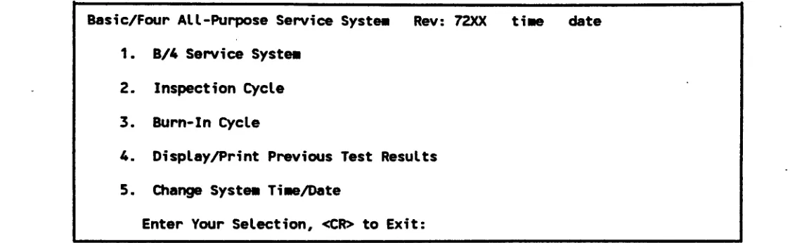
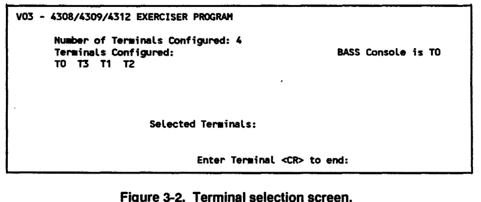
BASS Diagnostics Menu ... 3-3 Terminal Selection Screen ... 3-20
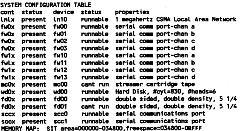
SIT Configuration Report ... 5-4
LIST OF TABLES
Table Page
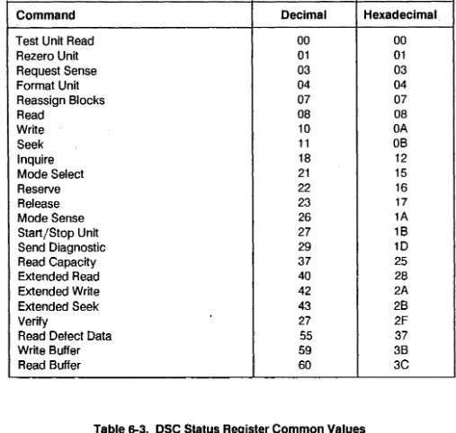
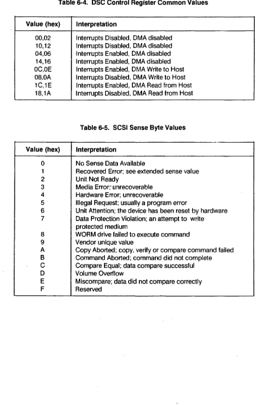
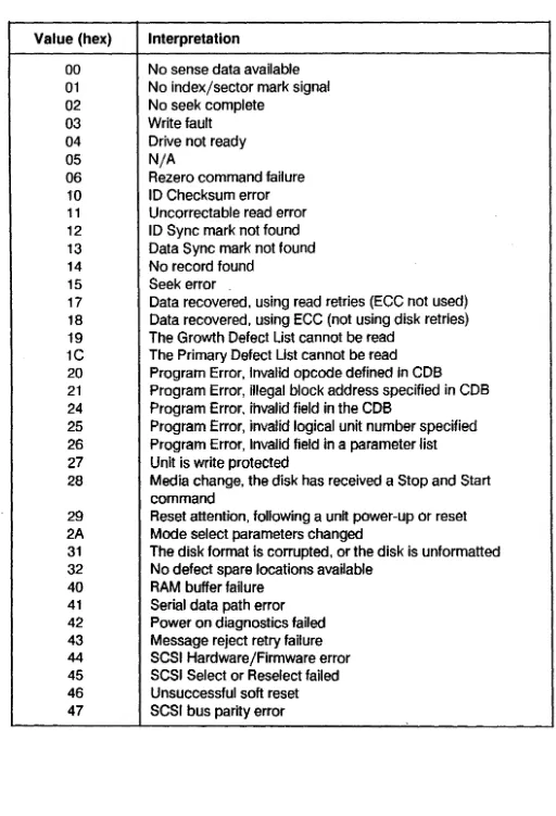
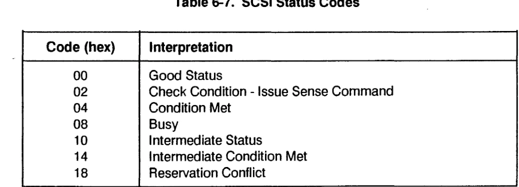
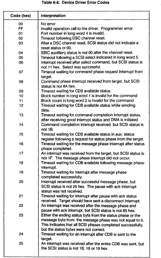
2-1 Syndrome Bit Decoding ... 2-10 6-1 Logic Test Names ... ~ ... 6-4 6-2 SCSI Commands ... 6-146 6-3 DSC Status Register Common Values ... 6-146 6-4 DSC Control Register Common Valyes ... 6-147 6-5 SCSI Sense Byte Values ... 6-146 6-6 SCSI Extended Sense Byte Values ... 6-148 6-7 SCSI Status Codes ... 6-149 6-8 Device Driver Error Codes ... 6-149 7 -1 DISKFS Function Key Assignments ... 7-8 7-2 DISKFS Data Types ... 7-10 7-3 6 Byte DCB ... 7-18 7-4 10 Byte DCB ... : ... 7-18 7-5 Controller Op-Codes ... 7-19 7 -6 MTS~S Data Types ... · ... 7 -39 7-7 Test Data Patterns ... 7-91 8-1 Pre-test Status Displays ... : ... 8-2 8-2 Pre-test LED Error Codes ... 8-3 8-3 Sense Switch Settings ... 8-4 8-4 Self-test LED Codes ... 8-5 8-5 DOB Status Codes ... 8-62 8-6 WDC Ending Status Codes ... .-... 8-63 8-7 WDC Status Codes ... 8-63 8-8 WDC Test Data Patterns ... 8-64
PREFACE
This manual describes the diagnostic programs provided for MAl 2000/2500/3000/4000 running the MAl BOSS/IX operating system, version 7.4. This information is provided as an aid for field service personnel in locating hardware problems to the board and socketed IC level.
The major topics covered in this manual and the changes made for this revision, are: Section 1
Section 2 Section 3 Section 4
Section 5 Section 6
Section 7
Section 8 Section 9 Section 10
Appendix A
M6204C
Introduction Error Logging BASS Diagnostics Diagnostic Executive
System I nteraction Test (SIT) Logic Tests
- Added Dual SCSI Controller Logic Test Function Select Tests
- Added Dual SCSI Controller Function Select Test Micro-Diagnostic System (MDS)
Disk Utilities (DUTIL) SCSI Disk Utilities (FAVI) - New Section
Installing Diagnostics - New Appendix
1.1
OVERVIEW
SECTION 1
INTRODUCTION
This manual describes the diagnostic features developed for the MAl 2000, 2500, 3000 and 4000 systems. The diagnostics described are for release 7.4A and above, though many apply to earlier releases as well. The features consist of a system error logging facility, which maintains a file of boot and runtime errors on the system, and a set of programs to aid in diagnosing system problems to various levels.
The error logging facility is included in the base system software, and so is available on all systems (unless the program files are deleted). Error logging is started automatically during the normal boot procedure. Access to the error log is available on-line, during normal system operation.
Most of the diagnostiC programs are distributed on tape or floppy. The exception is the Micro-Diagnostic System (MDS), which resides in system PROMS on MAl 2500, 3000 and 4000 systems (MDS is not available on the MAl 2000).
The Basic All-purpose Service System (BASS) diagnostic is an on-line system exerciser, and is the highest level set of diagnostic programs. All other diagnostic programs are off-line diagnostics, and require a special boot procedure (alternate load) or, in the case 'of MDS, invocation of the PROM routine from the boot menu.
The System Interaction Test (SIT), Logic tests, F,unction Select tests and Disk Utility (DUTIL) all operate under the control of the diagnostic Executive program (Section 4). These programs are distributed on the bootable
diagnostic media (DIA).
Instructions for installing the diagnostic Executive, SIT, Logic tests, Function Selects and BASS on the fixed disk are provided in Appendix A.
1.2
DIAGNOSTIC STRATEGY
The diagnostic programs are designed to provide an aid in trouble shooting at different functional levels. For instance, the BASS tests exercise system peripheral devices under the control of the operating system, and may be run in a multi-user environment. This is the highest level of diagnostic, and is mostly useful for detecting failure of the peripherals themselves.
At a lower level, SIT simulates operation in an operating system environment, but in a closely controlled manner. It checks for interaction problems between competing devices, and helps isolate system problems to a suspect board or boards. Logic tests, at a deeper level, further diagnose problems at the board level, followed by
Function Select tests which allow a degree of diagnostic to the component level. MDS is the lowest level diagnostic, allowing testing of the system logic.
Given this hierarchical structure of the diagnostic programs, a general diagnostic strategy would be as follows: 1. Check the error log to determine which parts of the system are failing. Errors may be logged that
havE! gone unnoticed during system operation.
2. If a peripheral device is suspect, use the BASS tests to exercise the device, and check for errors. 3. If the problem appears to involve the controllers, use SIT and/or Logic tests to check the functioning
of the suspect controller either in interaction with other controllers or alone. 4. Use the Function Select Tests to identify"failing chips on controller boards. 5. Use MDS to diagnose the system when errors prevent the system from booting.
Steps 1 through 3 and 5 can be performed in the field, and can reduce the amount of hit-or-miss board swapping. Step 4, involving Function Select tests, is generally appropriate only at the repair depot level.
The DUTIL diagnostic is primarily used only for formatting fixed disks. It does have some functionality useful as a diagnostic as well. It is run similar to the function selects, but may be of use at the Logic test level (step 3).
1.3
RELATED PUBLICATIONS
The following manuals provided related information. ' • BOSS/IX Technical Reference Manual, M6227 • MAl 2000 Service Manual, M8079
• MAl 2500/3000 Service Manual, M8108 • MAI4QOO Service Manual, M8205
In addition, there are several related controller service manuals, ,as listed in the system service manuals.
Introduction
1.4
NOTATIONAL CONVENTIONS
A few notational conventions have been adopted in this manual.
1.4.1
Keys and Key Sequences
Individual keys on the keyboard are referred to by their legend. Letter keys, for example the Individual keys on the keyboard are referred to by their legend. letter keys, for example the K key, is referred to by the letter in . normal type. When the reference occurs in running text, it is shown in bold type, as in the previous sentence. If it is shown on a displayed line, it is not bolded, e.g.:
K
OccaSionally, espeCially for non-letter symbols, we further enclose the key name in double quotation marks for added clarity, e.g., "/".
Some keys are either not marked, for instance the SPACE bar, or have different names depending on the
keyboard, such as the ENTER or RETURN key. In this later case, we always refer to it as the ENTER key. When there are more than one possible markings for a key, we have picked one to use through out the text which we believe is unambiguous.
MAl Basic Four terminals typically have a series of four keys, marked "I", "II", "III" and "IV", sometimes called. "Motor BarsH and sometimes "Control Keys." W& refer to these keys as CTl-l, CTl-II, CTl-1il and CTl-IV. A sequence of keys is occasionally used by the diagnostic programs to perform special functions. These
sequences consist of pressing and holding down the CTRl (or CONTROL) key while pressing some other key. These sequences are described by joining the two keys with a "plus" sign, e.g., CTRl +C.
1
.4.2
Entered and Displayed Informatio.n
Most messages displayed by they diagnostics are shown on displayed lines in normal type, for instance: This is a message
In some cases we use a reduced, non-proportional type, primarily for size and formatting reasons: This is a llessage
Rarely, a single word message is shown in running text enclosed in quotation marks, e.g., "ERROR."
Entering information, such as commands, into the system consist of typing the information followed by pressing the ENTER key. Rather than say that, we usually simply say enter:
the information
We mean, type the information shbwn and then press ENTER. On infrequent occasions we say something like, "Type
V
and press ENTER." They mean the same.1.4.3 Command Format Descriptions
Several diagnostics have commands associated with them. Commands typically consist of the command name followed by one or more arguments or parameters:
command param1 param2 ...
Parameters may
be
shown either by constants or variables. A constant is the 'actual value of the parameter, and is shown in normal type. A variable parameter may take any of several values, such as numeric values, and is shown in the format in italics. The legal values for the parameter willbe
described in the text. For example:command
A
valueThe parameter A is constant, and value is variable.
If a parameter is optional, it is enclosed in braces, for example:
command {value}
If two or more parameters are alternates (at most one can be used per command), they are separated by a vertical bar (I). If selection is optional, the parameters are enclosed in braces:
command {A
I
B}In this case, either A or B or neither may be used. If one of the alternatives must be used, they are enclosed in parentheses:
command
(A
I
B)1.5
ABBREVIATIONS
The following are some common abbreviations used in this manual. Others may be used, as explained in the text.
• BOT • CMB • CRC • DMA • EOT • IOPB • KB/MB • SCC • VFC
1-4
Beginning
of
TapeCentral Microprocessor Board CYClical Redundancy Check Direct Memory Access End of Tape
I/O Parameter Block
Kilobyte (1024 bytes)/Megabyte (1048576 bytes) Serial Communications Controller
SECTION 2
BOSS/IX ERROR LOGGING
2.1
OVERVIEW
The BOSS/IX operating system supports error logging as a standard feature. Error logging is carried out in two
stages. Errors are first logged to memory. Up to eight errors can be logged in memory. In addition, an error log
process periodically updates an error log file on the fixed disk. This error log process runs as a background
process started automatically when the system enters multi-user mode.
A system command,
/sys/errlog,
displays the error log record and sets attributes of the error logging process.
The usual error log file is /etc/error.log.
This file can only be displayed by using the errlog command. The p
and cat commands do not provide meaningful output.
2.2
THE ERROR LOG COMMAND
A single command is provided to display the contents of the error log and to set attributes of the error logging
process. The general syntax of the command is:
/sys/errlog
{parameter1 ... parameterN}.
where the parameters are selected from the following:
file
-quiet
-initial
size
=errors
=
-mem
-tape
-term
-printer
-comm
-disk
-text
M6204C
The name of the error log file, usually /etc/error.log.
Used when starting the er-ror monitoring and file update as a background process.
Initializes the specified error log file, clearing out all existing entries. The file is initialized
to the size and starting number specified by the size
=and errors
=parameters.
Sets·the maximum number of errors recorded in the error history log. The default size is
100. The size can be set only when initializing the error log file.
Sets the current starting error number in the error history log. The default is
1.The
error number can be set only when initializing the error log file.
Displays memory errors only.
Displays tape errors only.
Displays terminal port errors only.
Displays printer errors only.
Displays communications errors only.
Displays disk errors only.
Used only with the -disk option, this displays descriptive text for each disk error.
2.2.1 Displaying the Error Log
Use the errlog command to display the error log disk file or the memory error log. To display the disk file, you
must specify the file name, usually /etc/error.log. If you do not specify the file name, only the errors logged in
memory are reported.
Display the entire disk error log file using this command:
/sys/err1og /etc/error.log
To display only errors of a certain type (e.g., memory, disk, tape, and so on), use the appropriate command line
option as listed in section 1.2. For example:
.
/sys/err1og /etc/error.log -tape
2.2.2 The Error Log Display
The error log file contains two types of error records: "By Type· and ·Chronological.· The By Type log is at the
beginning of the error log file, followed by the Chronological log.
The By Type records contain 2 entries for each type
of
error. The first entry indicates the number of occurrences
of the error. The second entry describes the last occurrence of this type of error. The error types are very broad,
such as "disk error" or "memory parity error.· For example, an entry for Winchester disk errors is shown:
Winchester disk
Minor: 35 Type:-2
A: 8241 B: 1
First: Apr 14 1987 09:30:43
Last: Apr 14 1987 09:30:43
c:
0 D: 0T: 28 U: 95992931 V: 40
Count: 1
Rev:
E: 0 Text:
The first line indicates the major device by common name (Winchester disk). the number of errors (1) of this
type. and the date of the first occurrence. The following lines giVe specific information on the latest error of this
type, including the minor device number and error type. The information provided is described in later sections.
For Winchester disk errors only, the additional information can
be
displayed as text. This is displayed by the
-disk and -text options on the errlog command:
/sys/errlog /etc/error.log -disk -text
The Chronological log maintains a chronological list of errors that have occurred since the error log was last
initialized. Errors are logged up to the maximum number specified when the file was initialized (default
=100).
Older errors are then replaced with new errors. The errors are displayed starting with the most recent.
Error Logging
The format of entries in the Chronological log similar to that of the By Type log, except that an entire log entry for each error is displayed. For example:
Nu~r: 6 Nu~r s;nce boot: 6 C8rtr;dge tape M;nor: 0 Type: -62
A: 39 B: 7 C: 0
T: 86A0 U: 4000 V: 0
Date: 100 Apr 16 1987 15:04:43 Class: F
D: 0
Rev: A3
E: 16
Text:
Nullber: 5 Nulllber s; nce boot: 5 Date: Wed Apr 15 1987 14: 54: 06 illegal instruct;on Type: -32767 Class: Rev:
A: 44 B: 1 C: 0 D: 0 E: 0
T: AC1A Nulllber: 4 CMB
A: 0
T: 10 Nulllber: 3 CMB
A: 0 T: 10 Nullber: 2
U: 0 V: 0 Text:
Nuilber s;nce boot: 4 Date: Wed Apr 15 1987 13:10:47 Minor: 1 Type: -32767 Class: Rev:
B: 0 C: 0 D: 0 E: 0 U: 0 V: 0 Text:
Nu~r since boot: 3 Date: Wed Apr 15 1987 13:10:46 Minor: 1 Type: -2 Class: Rev:
B: 0 C: 0 D: 0 E: 0 U: 0 V: 0 Text:
Nullber since boot: 2 . Date: Tue Apr 14 1987 09:30:43 Winchester disk Minor: 35 Type: -2 Class: Rev:
A: 8241 B: 1 C: 0 T: B6F4 U: 0 V: 0
D: 0 E: 0
Text:
Nulllber: 1 Nullber since boot: 1 Date: Tue Apr 14 1987 07:57:00
.a.ary .anage.ent Type: -32767 Class: Rev:
A: 193 B: 1 C: 337 D: -1191165876 E: -64510 T: B5F4 U: 0 V: 0 Text:
2.3
ERROR INTERPRETATION
The following subsections describe the interpretations of the error reports for each error type.
Fields A through E are decimal fields. Fileds T, U and V are hexadecimal fields. When interpreting the
hexadecimal fields, bit 0 is the least significant bit (LSB). For example, fields A and U in error number 6 in the previous example have the following interpretation:
A:
39 A decimal value, indicating block 39 is in errorU:4000 A hexadecimal value, bit 14 is ON indicating "end of data".
2.3.1 System Trap Errors
There is a large variety of errors that may be assigned to major device number
o.
These are generally caught by a system trap. The common names displayed for device number 0 is determined by the minor device number, as follows: MinorDev Numbero
12
3 4 5 6 7 8 9 10 11 12 13 14 15 16 17 18 19 20 2122
23 24 25 26 27 2829
30 31 Name bus error illegal instruction bptjtrace (not used) iot (not used)power fail system call trap instruction
parity (MAl 2000 only) PIRQ (not used)
floating point (not used) memory management odd address
divide by 0 check overflow privilege error halt format
illegal inst. (f-line) (MAl 2500/3000/4000 only) coprocessor protocol (MAl 2500/3000/4000 only) PMMU configuration (MAl 2500/3000/4000 only) PMMU illegal operation (MAl 2500/3000/4000 only) PMMU access level (MAl 2500/3000/4000 only) multiple bit memory (MAl 2500/3000/4000 only) single bit memory (MAl 2500/3000/4000 only) cache parity (MAl 2500/3000/4000 only) calendar (MAl 2500/3000/4000 only) UPS transition (MAl 2500/3000/4000 only) EIA trans. parity (expansion interface) EIB trans. parity (expansion interface) power fail (expansion unit) (MAl 4000 only) 'UPS transition (expansion unit) (MAl 4000 only)
The following paragraphs contain detailed descriptions of the error log field values for each of these errors. The errors are groups based on common field value interpretations.
2.3.1.1
Bus
ERROR, MEMORY MANAGER AND ODD ADDRESSMajor: 0
Minor: 0 = Bus Error
10 = Memory Manager 11
=
Odd AddressClass: N/A
REV: N/A
A: process id
B: process mode: 1 = user mode
o
= supervisor modec:
MAl 2000 - Reference classification 7 interrupt acknowledge 6 supervisor program 5 supervisor data 4 not used3 not used 2 user program 1 user data
o
not usedMAl 2500/3000/4000 - 68020 special status word
Error Logging
Note: This field is expressed in decimal notation, but is a bit oriented value. You must first convert the decimal value to a hex value, then interpret the bits as follow:
Bit
15 Fault on Stage C of the instruction pipe
14 Fault on Stage B of the instruction pipe
*
13 Return flag for Stage C of the instruction pipe
*
12 Return flag for Stage B of the instruction pipe11-9 0
*
8 Fault/Return flag for data cycle 7 Read /Modify /Write on data cycle
6 Read/Write for Data Cycle: 1 = Read; 2 = Write 5-4 Size code for data cycle
3 0
2-0 Address space for data cycle
*
1 = Rerun faulted bus cycle, or Run pending prefetcho
= Do not rerun bus cycle0:
MAl 2000 - Type of access 1 Reado
WriteMAl 2500/3000/4000 - Data cycle fault address
2-6
E: MAl 2500/3000/4000 - Value of PMMU status register
Note: This field is expressed in decimal notation, but is a bit oriented value. You must first convert the decimal value to a hex value, then interpret the bits as follow:
Bit
15 Bus error. A bus error was returned to the PMMU from physical memory during a table search.
14 Umit violation. The table index exceeded a limit field.
13 Supervisor violation. An attempt was made to access a supervisor only page.
12 Access level violation. Access fields have been exceeded. (Access level protection is not used.)
11 Write protected. An attempt was made to write to a read-only page. 10 Invalid page. A page descriptor was fetched which was marked "invalid."
9 Modified page. This bit is set when a page has been modified. 8 Not used.
7 Globally shared. Shared bit is set in the logical address descriptor. 6-4 Not used.
3-0 Level number. Number of tables used during the translation.
T: Program counter at error.
MAl 2000. The program counter value, which is the address of the instruction that was executing at the time the fault was detected, could be advanced by up to 5 words.
MAl 2500/3000/4000. The program counter value, which is the address of the instruction that was executing at the time the fault was detected, is not necessarily the instruction that caused the error to occur, due to the overlapped execution performed by the CPU.
U: MAl 2000 -Instruction being processed at the time the error occurred (see explanation for field
T.)
MAl 2500/3000/4000 - Stage B instruction fault' address.
V: MAl 2000 - Address being accessed when the error occurred.
MAI2~00/3000/4000 -Instruction pipe Stage C fault address
2.3.1.2
MISCELLANEOUS TRAPSThese error log field descriptions apply to the following errors: Major: 0
Minor: 1 4
5
6
12 13 14 15 16 17 18 19 20 21 22 30CLASS: N/A
REV: N/A
illegal instruction power fail
system call trap instruction divide by 0 check overflow privilege error halt format
illegal inst. (f-line) (MAl 2500/3000/4000 only) coprocessor protocol (MAl 2500/3000/4000 only) PMMU configuration (MAl 2500/3000/4000 only) PMMU illegal operation (MAl 2500/3000/4000 only) PMMU access level (MAl 2500/3000/4000 only) power fail (expansion unit) (MAl 4000 only)
A: process id B: process mode:
1 = user mode
o
= supervisor mode C: not used0:
not used E: not usedT: Program counter at error.
Error Logging
MAl 2000. The program counter value, which is the address of the instruction that was executing at the time the fault was detected, could be advanced by up to 5 words.
U:
V:
Z:
M6204C
MAl 2500/3000/4000. The program counter value, which is the address of the instruction that was executing at the time the fault was detected, is not necessarily the instruction that caused the error to occur, due to the overlapped execution performed by the CPU. not used
not used not used
2.3.1.3
PARITY ERROR(MAl 2000
ONLY)2-8
Major: 0 Minor: -7
Type: -32767, nonexistent memory was specified. CLASS: N/A
REV:
N/AA: process id
B:
N/AC:
N/A0:
N/AE:
N/AT: Address indicating the 128 KB bank that failed. The following addresses (in hex) are for full 256 KB boards. If the system contains 1,28 KB boards, adjust the table accordingly. (Boards are determined by switch setting, not by position in the staCk.)
Board Address Range 1 00000 to 3FFFF 2 40000 to 7FFFF 3 80000 to BFFFF
4
COOoo
to FFFFF5
100000 to 13FFFF 6 140000 to 17FFFF 7 180000 to 1 BFFFF8 1COOOOto 1FFFFF
U: Parity status register Bit
7
0:
user mode when failure occurred1: supervisor mode when failure occurred 6 1: parity error occurred in upper byte
5
1: parity error occurred in lower byteo
0:
parity error on CMB access1: parity error on system bus controller access Note: Bits
5
and6
are undefined for 2 + artwork eMB's.If the error occurred during access by a system bus controller, bit 7 is undefined.
V:
Z:
N/A N/A
Error Logging
2.3.1.4
SINGLE AND MULTIPLE BIT MEMORY ERRORS (MAl2500/3000/4000
ONLY) Major: 0Minor: 23 (multiple bit) 24 (single bit)
Type: -32767, nonexistent memory was specified. CLASS: N/A
REV: N/A
A: process id B: process mode:
1 = user mode
o
= supervisor modeC: Count of single bit errors (single bit memory only).
0:
Bus cycle: 0= DMAcycle 1 = CPU cycleE:
Number of single bit error restarts, where a restart occurs when single bit error logging is disabled.T: Upper physical address lines at time of error. Range is 100000 to 3FOOOOO. U: Low order 7 bits of the memory status register .
Bit
2 0: data cache inhibited 1 : data cache operating
1 0: no single bit error occurred
.
1 : a single bit error occurred ans was corrected
o
0: no multiple bit error occurred1 : a non-correctable multiple bit error occurred
V:
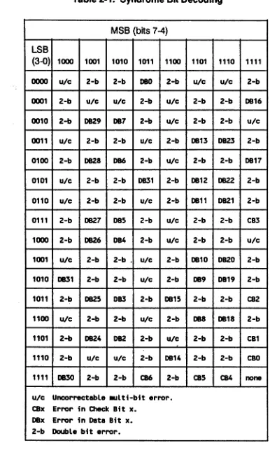
Syndrome byte. The syndrome bits are interpreted according to the following table. Bit 7 is always 1.Z:
N/ATable 2-1. Syndrome Bit Decoding
MSB (bits 7-4)
LSB
(3-0) 1000 1001 1010 1011 1100 1101 1110 1111
0000 ute 2-b 2-b DBO 2-b ute ute 2-b
0001 2-b ute ute 2-b ute 2-b 2-b DB16 0010 2-b 0829 DB7 2-b ute 2-b 2-b ute
0011 ute 2-b 2-b ute 2-b DB13 DB23 2-b 0100 2-b DB28 DB6 2-b ute 2-b 2-b DB17 0101 ute 2-b 2-b DB31 2-b DB12 0822 2-b 0110 ute 2-b 2-b ute 2-b DB11 DB21 2-b 0111 2-b 0827 DBS 2-b ute 2-b 2-b CB3 1000 2-b 0826 DB4 2-b ute 2-b 2-b ute
1001 ute 2-b 2-b . ute 2-b DB10 DB20 2-b 1010 0831 2-b 2-b ute 2-b DB9 DB19 2-b 1011 2-b 0825 DB3 2-b DB1S 2-b 2-b CB2 1100 ute 2-b 2-b ute 2-b DB8 DB18 2-b 1101 2-b 0824 0B2 2-b ute 2-b 2-b CB1 1110 2-b ute ute 2-b DB14 2-b 2-b cao
1111 0830 2-b 2-b CB6 2-b CBS CB4 none
ute Uncorrectable .ulti-bit error. CBx Error in Check Bit x.
DBx Error in Data Bit x. 2-b Double bit error.
2.3.1.5
DATA CACHE PARITY(MAl 2500/3000/4000
ONLY) Major: 0Minor: 25
Type: -32767 nonexistent memory was specified.
CLASS: N/A
REV:
N/A
A: process id
B:
mode1 = user process
o
= supervisor processError Logging
C: Count of data cache errors. The count reported may be less than the actual count, since the data cache can
be
turned off after a specified number of errors and then turned back on. 0:N/A
E:
N/AT: Oata cache parity status register.
U:
V:
Z:
M6204C
Bit
7 1 = Cache Parity Error in byte 0 (000-007)
o
= No Cache Parity Error in byte 36 1 = Cache Parity Error in byte 1 (OOB-015)
o
=
No Cache Parity Error in byte 35 1 = Cache Parity Error in byte 2 (016-023)
o
= No Cache Parity Error in byte 34 1 = Cache Parity Error in byte 3 (024-031)
o
= No Cache Parity Error in byte 3 3 Address bit 11 at time of error. 2 . 0 = Cache set to 11 = Cache set to 0
1 0 = Parity error in tag bits A 1B-A 11 1 = No error in tag bits A 1B-A 11
o
0 = Parity Error in tag bits A25-A 19 1 = No error in tag bits A25-A 19N/A
N/A
N/A
2.3.1.6
CALENDAR(MAl 2500/3000/4000
ONLY)2-12
Major: 0 Minor: 26
Type: -32 Calendar chip is not keeping correct time. -62 Timeout reading calendar chip.
-132 Battery is low or dead. CLASS: N/A
REV:
A:
B:
C:
D:
E:
T:
U:
V:
Z:
N/A
Calendar Chip Time (in seconds since midnight, 1/1 /SO) System Time (in seconds since midnight, 1/1/80)
2.3.1.7
UPS
TRANSITION(MAl 2500/3000/4000
ONLY)Major: 0
Minor: 27 Base unit UPS Expansion unit UPS 31
Type:
N/A
CLASS:N/A
REV:
A:
B:
c:
D:
E:
T:
U:
V:
Z:
M6204C
N/A
on/off flag
1 = UPS on
o
= UPS offtotal count of UPS transitions since boot.
N/A
N/A
N/A
N/A
N/A
N/A
N/A
Error Logging
2.3.1.8
ExPANSION INTERFACE TRANSMISSION ERRORS(MAl 3000/4000
ONLY)2-14
Major: 0
Minor: 28 29 Type: N/A
CLASS:
N/AREV:
N/AEIA transmission parity error EIB transmission parity error
A: process
id
B: process mode:
1 = user process
o
= supervisor processC: N/A
0: N/A
E:
N/AT: program counter at e,rror
U: Expansion interface interrupt 7 status register
.att
0 1 2
3
4 5-7
V:
N/AZ:
N/ATransmission parity error has occurred in the low byte Transmission parity error has occurred 'in the high byte Error occurred during DMA cycle
Error occurred during read cycle
Error occurred during interrupt acknowledge cycle not used
2.3.2 1/2 Inch Streamer
Major:
2
Minor:
0
Type:
-2-26 -33 -62 -89 -98 -111 -129 -32767
I/O error
Device is busy
Bad system call
Time out
Device off-line
Tape media error
Parity error
Failed attempt to open
Nonexistent memory specified by system call
Error Logging
These errors are all fatal, and so are logged. Non-fatal errors, such as read overflows, file mark
read, no write-ring, etc., are not logged.
CLASS: F
(All logged errors are classified as fatal (F).)
REV:
N/A
A:
Bytes processed since BOT.
B:
Total files processed since BOT.
C:
Soft errors since BOT.
0:
Block size at error.
E:
Operation in progress:
Val!J~
0
test unit ready
1
rewind
3
get sense (status)
5read block size
8
read
10
write
16
write file mark(s)
17space tape
18inquiry
19verify
20
recover buffered data
21mode select
25
erase
26
mode sense
27
load/unload
T:
Drive status
2-16Bit
3130
2928
2726
25
24
23
22 2120
19 18 17 16 15 14 13 12 11 10 9 8 7 65
4 3 2 1o
Hard error
Corrected error
Filemark encountered
10 Mark sensed
EOTsensed
Load point sensed
Formatter busy (tape active, streaming)
Data busy (tape active, command in progress)
Tape loaded and ready .
Write protected
High speed selected
Tape is On-line
Tape is rewinding
not defined
Unit number of selected tape drive
Unit number of selected tape drive
TapeTC
SCSITC
Block underrun
SCSI DMA generated parity
Tape overrun
Parity in
Tape DMA parity error
SCSI DMA parity error
Tape DMA length terminal count
SCSI DMA length terminal count
Manual SCSI DMA request
Manual Tape DMA request
Dynamic RAM refresh enable
SCSI to Tape
Error Logging
U: Controller Status
V:
Z:
M6204C
This is a 4 byte field. The first and third bytes are sense bytes, and interpreted as follows:
Bit
7 Filemark 6 End of Tape
5 Requested block length mismatch 4 not defined
3-0 Sense key, as follows:
o
No further information 1 Recovered error 2 Not ready3 Medium error
4 Hardware error (device failure) 5 Illegal request
6 Unit attention 7 Write protected 8 Blank tape 9 not defined A not defined
B Aborted command C not defined
o
Volume overflow E Miscompare F not definedThe second and fourth bytes contain secondary error codes, interpreted as follows:
Value
00 No error
20 Illegal SCSI command 43 Data buffer parity error 50 No data detected
51 Function did not complete in specified time
52 Tape position error - BOT was not indicated after a Rewind, Load or Long Erase. 53 An error occurred before the requested tape drive command was completed. 54 Data buffer is not empty
55 Fixed bit is set while in variable block mode or is not set while in fixed block mode. 56 Data transfer error occurred, host to controller
57 Data transfer error occurred, controller to host
58 Verify command does not support byte compare mode
59 Space command does not support spacing to physical End of Data 5A Diagnostic Self Test not supported
5B Command Sequence Error 5C Unit Select Error
50 Variable block length greater than 64 KB 5E Unable to obtain ownership of buffer 5F Command parameter error
60 Status error from target (COpy command) N/A
N/A
2.3.3 Cartridge Tape
2-18
Major: 6 Minor: 0 Type: -2
-62 -63 -89 -91 -97 -98
CLASS: F N S
I/O error
Operation has timed out Media is write protected Device is off-line
End of data No cartridge Tape media error
Fatal error. Fatal errors are: controller errors, tape read/write abort errors, and device timeouts.
Non-fatal error. Non-fatal errors are: no cartridge, write protected cartridge, and drive not ready.
Summary of tape statistics. Summary statistics are logged whenever that tape
cartridge is rewound. It is not an error, and is not logged in the "by type" log. The log fields have different meanings for type S entries, as described below.
REV: N/A
.
A: Block number at error (error types F and N)
Total number of blocks (512 bytes) processed (error type S). B: Total files processed since BOT.
C: Soft error count as returned by the drive. D: Underrun count as returned by drive.
E:
S
F,N
not used
Operation in progress: Value Command
18 append
17 raw write 16 raw read
5 read drive status
4 erase
3 retension 2 rewind
1 space forward tape
o
controller initializeError "Logging
T:
S not usedF,N Drive status
Bit
Status15
Set if any bits in high byte are set14
Cartridge is not in place13
Catastrophic error12
Write protected cartridge11
End of media10
Unrecoverable data error 9 Bad block not located 8 File mark read7 Set if any bits in low byte are set 6 Illegal command
5
No data detected4
Marginal block detected3
Beginning of media2
Bus parity error1 End of recorded media
0
Power on/ResetU:
S not usedF,N Controller status Bit Status
15 Operation successful
14
End of data13
lOPS parameter error12
Chain processing terminated11
Filler sent10
Read to end of media 9 Sad data transfer 8 No cartridge7 File mark detected 6 Write protected
5
Aborted4
Not erased in area of append3
Wrote to end of media2
Powerfail/reset1
Catastrophic error0
Error, drive status requiredV:
N/AZ:
N/A2.3.4 Floppy Disk (MAl 2000 only)
Major: 7
Minor: 0 - 31 = drive 0 32 - 63 = drive 1
The number indicates the disk partition number, usually only 0 or 32.
2-20
Type: -63 Write protected -86
-99
Drive seek error or data transfer error Originally mounted diskette was not found CLASS: N/A
REV: N/A
A: Starting block of transfer B: Number of blocks requested
C: N/A
0:
N/AE:
N/AT: Driver status
Bit Qgmmand
8 interrupt
7 error
4 seek
3 recal
2 write
1 read
U:
ControHer statusrut
seek/recalmm1
7 not ready not ready
6 write protect N/A
5 head loaded N/A
4 seek error record not found
3 CRC error CRC error
2 track 0 lost data
1 index pulse data request (ORO)
0 busy busy
write not ready write protect write fault
record not found CRC error
lost data
data request (ORO) busy
;'
Error Logging
V: Drive control
Bit Command
5 enable write verification 4 disable error messages 3 not used
2 retires disabled 1 not used
Z:
N/A
2.3.5 Printer Filter (Printer)
2-22
Major: 8 Minor:
o
1 2 3 45
6 7 8 9 10 11 12 13 14 15 MAl 2000CMB parallel port CMB serial port A CMB serial port B
port 1 on the first 4-way port 2 on the first 4-way port 3 on the first 4-way port 4 on the first 4-way port 1 on the second 4-way port 2 on the second 4-way port 3 on the second 4-way port 4 on the second 4-way port 1 on the third 4-way . port 2 on the third 4-way port 3 on the third 4-way port 4 on the third 4-way port 1 on the fourth 4-way and so on
Type: -62 Operation has timed out -108 Printer
110
transmission error CLASS: N/AREV: N/A
A:
Current page number since openB:
Current line numberC:
Current column position, usually the end of the lineD:
MBF printer protocol:1 on
o
offE:
Printer type Bit Printer5 Okidata82a
4 Diablo
3 MVP
2 Whisper
1 Tritel 0 Printronix
MAl 2500/3000/4000 CMB parallel port CMB serial port A CMB serial por