© 2019, IRJET | Impact Factor value: 7.211 | ISO 9001:2008 Certified Journal
| Page 7001
Development of Special Tool with Fixture for Process Optimization of
Hex Key Hole
Lokesh Singh
1, Mukesh kumar
21
M-Tech Student, Mechanical Engineering, Delhi Institute of Technology, Management & Research, HR, India
2
M-Tech Student, Mechanical Engineering, Delhi Institute of Technology, Management & Research, HR, India
---***---
Abstract — The Competitive atmosphere in manufacturing sector is primarily driven by customer demand for products that are durable and cost effective without a compromise on quality. These requirements trickle down to all the processes such as design, validation, prototyping and production that are involved in delivering a product to customers meeting their requirements. While the quality aspect is usually achievable by using modern production methods such as Electrical Discharge Machining, the cost effectiveness aspect gets diminished. Therefore, a balance must be achieved so that the criteria for both quality and cost effectiveness can be met. This paper postulates one such balanced methodology for development of special tool with a fixture for hex key hole cutting.The specialized tool is designed using Solid works CAD software package based on the critical design variables such as the dimensions of key hole, depth of keyhole, etc. The tool is then analyzed using classical analytical techniques. These results are in turn validated with finite element analysis using Altair HYPERWORKS Software package.
The material selected for specialized tool with fixture is HSS and is developed for utilization on lathe. The benefits of this methodology is decrease in cost of machining by 20 times and reduction in production time by 10 times all the while maintaining same level of quality in the output.
Keywords—Broaching, Hex key, Lathe, EDM, FE Analysis.
I. INTRODUCTION
The competitive atmosphere in manufacturing sector has made it mandatory that unorthodox methodologies are developed that are a perfect mix of disruptive innovations and classical machining processes and equipment. This in turn ensures that the newly developed methodologies are easy to adopt both in terms of process setup and manpower training. The focus of this paper is a specialized tool developed for use on lathe such that this combination can compete with processes like Electrical Discharge Machining (EDM) [1] in terms of process time, production costs and output quality.
The operating principle of the tool is that of a rotary broaching. Rotary broaching is a very useful way of producing hexagonal or other polygonal holes in metal. It can also be used to produce internal splines and other profiles. It is especially useful for producing such profiles in short blind holes.
The principle of rotary broaching is quite straight forward [2]. A hole is drilled in the work piece with a diameter of slightly more than the minimum cross section diameter of the shape to be broached. With the work piece rotating under power a shaped cutter that can freely rotate is brought up to the hole at a slight angle and it is pressed into the hole. The rotating work piece causes the cutter to revolve and, because of the slight angle, the corners of the cutter come into contact in turn, each taking a peck as it does so. After one revolution the cutter has shaved a little metal from the hole, and as the tool is fed into the hole during subsequent revolutions, the hole is gradually broached to the shape of the cutter until the required depth is reached.
The material selected for the tool is traditional HSS due to its availability and versatility. The fidelity of tool is inspected using analytical methods which are then validated with simulation results.
II. LITERATURE REVIEW
© 2019, IRJET | Impact Factor value: 7.211 | ISO 9001:2008 Certified Journal
| Page 7002
mm and feed of 0.25 mm/rev. Similarly, low w/p surface temperature was obtained at cutting speed of 150 m/min, depth of cut of 0.5 mm and feed of 0.25 mm/rev. Whereas, at cutting speed of 250 m/min, depth of cut 1.00 mm and feed of 0.25 mm/rev, the maximum MRR was obtained. Thereafter, optimal range of tool wear, work piece surface temperature and MRR values were predicted. Finally, the relationship between factors and the performance measures were developed by using multiple regression analysis.
[Ved Prakash Singh Parihar, M. A. Saloda, B.P. Nandwana and M. S. Khidiya] Cutting forces during machining can be a serious problem influencing manufactured parts quality, precision, tool service life, lathe performance and cutting rates [4]. This paper presents an analysis of cutting mechanics in turning process. Cutting forces have significant impact on cutting process stability, which affects the quality of manufactured parts and productivity rates. The cutting forces applied on the surface of work piece by Lathe tool is measured using experimental setup. The forces work on the work piece applies in three directions as longitudinal, axial and lateral directions. The experimental setup is used to find all these forces and optimization of result found. The cutting forces can be measured using Dynamometer. The experiment is performed by changing three parameters in the cutting process as feed, spindle speed and depth of cut and their effects on cutting forces is analyzed for changing parameters.
[Poonam D. Kurekar, S.D. Khamkar] studied phenomena associated [5] with the effect of temperature and cutting forces on the tip of Single Point Cutting Tool. Temperature at tool-tip is measured, generated in high speed machining operations. Temperature at cutting point of the tool is crucial parameter in the control of the machining process. Specifically, three different analyses are compared to an experimental measurement of temperature in a machining process at slow, medium and high speed. Tool-work Thermocouple technique is used for measuring temperature on tip of tool at various cutting parameters (depth of cut, speed and feed rate) and it found that with increase of speed and depth of cut temperature at tip of cutting tool increases. Cutting forces are analytically determined and stresses are found out at tip of cutting tool. Single Point Cutting Tool is modeled in CATIA software and model is then imported in ANSYS software for analysis. By applying temperature readings, temperature distribution on cutting tool is found out. Also from stress analysis of cutting tool it is observed that the effect of cutting force is more as compared to thrust force.
III. DESIGN OF SPECIAL TOOL WITH FIXTURE
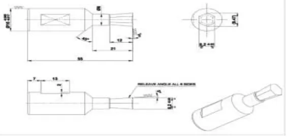
The design of the tool is primarily dependent on various parameters such as key hole size, depth, approach angle, etc. A CAD model is drafted using SOLIDWORKS. The finalized dimensions are shown in figure 1.
Figure 1. CAD Drawing of the Special Tool
[image:2.596.160.443.456.591.2]The CAD model of the special tool is shown in figure1 below
© 2019, IRJET | Impact Factor value: 7.211 | ISO 9001:2008 Certified Journal
| Page 7003
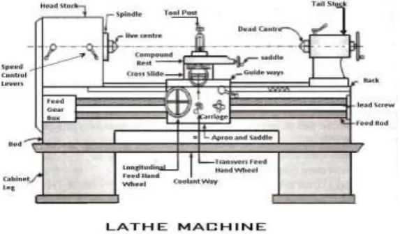
In the process of hex key hole cutting, the job is held in the four jaw chuck or three jaws chuck depending on the accuracy required for the job and tool is fed from the tailstock with using the special designed revolving type holder. This creates a shearing effect around the edges of the form being cut. Essentially only a section of the form is being cut at any given time – which greatly reduces the amount of cutting pressure needed to form the desired feature.
Fig. 3. Representational Image of Lathe Machine
[image:3.596.156.443.151.319.2]The tool holder has a spindle which spins independently of the rest of the holder. Thus, when we are producing the internal hex key hole on a lathe, when the tool meets the rotating part, it begins spinning at the same rate as the part /Job rotating and feed is given by the rotating the tail stock. In this process the tool shape is transferred on to the job and depth is controlled with feeding of tailstock.
[image:3.596.181.417.444.570.2]Figure 4 shows the specialized tool with fixture that is used for hex key hole cutting. Figure 5 shows the special tool being used for hex key hole cutting.
Fig. 4. Special Tool with Fixture
[image:3.596.179.417.597.734.2]© 2019, IRJET | Impact Factor value: 7.211 | ISO 9001:2008 Certified Journal
| Page 7004
IV. DESIGN CALCULATION FOR SPECIAL TOOL
Analytically cutting forces and thrust forces are calculated by using different depth of cut (d) and feed rate (f) are as follows:
For d = 0.5 mm and f = 0.5 mm/rev
Fc = 1593 × f0.85 × d0.98 N
= 1593 × 0.50.85 × 0.50.98
Fc = 448.05 N
Where d = Depth of Cut f = Feed rate
Fc = Cutting Force Thrust Force Calculation
Average co-efficient of friction on the tool face, μ = 0.7
Rake angle, α = 3°
μ =
0.7=448 tan3 +Ft
448- Ft tan3
Thrust Force, Ft = 279.85 N
Similarly, other calculations are done by using above formulae for different depth of cut and feed rate are tabulated in Table 1 as follows:
Feed Rate (mm/rev) Depth of Cut (mm) Cutting Force Fc (N) Thrust Force Ft (N)
0.5
0.5 448.05 279.85
1 883.77 552.12
1.5 1314 820.82
Table 1. Calculation of Forces During Operation
Similarly, the stress on tool can also be calculated. For
Depth of Cut = 0.5 mm
Shear angle tanφ = Tan φ = 0.1235 cos3°
1- 0.1235 sin3°
φ = 7.074°
Normal Force Fn =
© 2019, IRJET | Impact Factor value: 7.211 | ISO 9001:2008 Certified Journal
| Page 7005
= 163.87 MPa
Similarly, stress induced can be calculated for depth of cut of 1 mm and 1.5 mm. This is tabulated in Table 2.
V. STRUCTURAL ANALYSIS OF SPECIAL TOOL
The CAD geometry of the tool is modelled using solid modelling software package SOLIDWORKS. The CAD data is then converted to Initial Graphics Exchange Specification (IGES/STP) format and imported into pre-processing software Altair HYPERMESH. The tool is discretized by meshing process into 3d tetra elements [6]. A sensitivity check is performed to ascertain the correct mesh size suitable for the analysis. The element size ultimately selected Is a range of 0.8mm to 4mm. Additionally, fine mesh is provided in the stress concentration zones such like tool tip and taper end neck. The tool is then analyzed using OPTISTRUCT solver [7]. The post- processing of results is then done in HYPERWORKS.
The Stress are plotted with respect to different depth of cut i.e. for 0.5 mm, 1 mm and 1.5 mm.
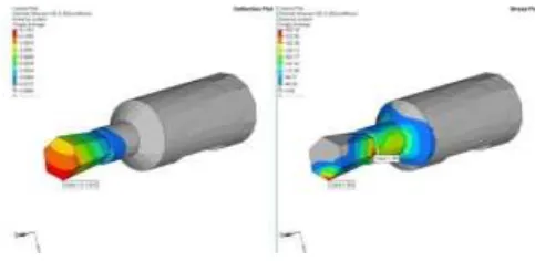
Figure 6. shows the stress plot for depth of cut of 0.5 mm. The maximum stress of 184 MPa is noted at the interacting tip of the tool. It is to be noted that another critical area, the taper neck, has to be evaluated. The Maximum stress in this zone is 177 MPa. Both the values are well below the Yield limit of HSS.
[image:5.596.174.416.323.441.2]Therefore, tool will not fail in these conditions.
Figure 6. Deflection and stress plot for 0.5mm Depth of Cut
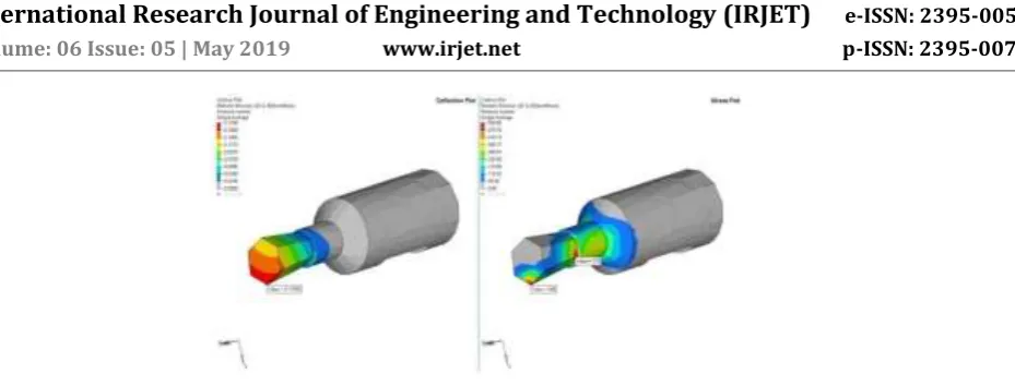
[image:5.596.177.418.502.622.2]The results for depth of cut of 1.0 mm is shown in Figure 7. The stress at the interacting tool tip is 363 MPa and in the taper neck area is 349 MPa. It is again well below the Yield limit of HSS. Therefore, tool will not fail in these conditions.
Figure 7. Deflection and stress plot for 1 mm Depth of Cut
© 2019, IRJET | Impact Factor value: 7.211 | ISO 9001:2008 Certified Journal
| Page 7006
Figure 8. Deflection and stress plot for 1.5mm Depth of Cut
VI. CONCLUSION AND FUTURE SCOPE
There is good correlation between the two sets of results as seen in Table 2. It is clear that with increase in depth of cut stress on cutting tool also increases. When both Fc and Ft applied on cutting tool is stress maximum. Stress is nearly equal when both Fc and Ft and only Fc are applied. But stress on cutting tool due to thrust force is less as compared to cutting force.
Depth of cut Analytically Calculated Stress (MPa) Stress by FEM Analysis (MPa) Correlation
0.5 163.87 184.01 89%
1 301.14 363.83 83%
1.5 507.7 539.66 94%
Table 2. Correlation of Analytical and FE Analysis Results
It can also be seen that there is good correlation between analytical results and FEA based results thereby validating the design of the tool.
The benefits of this methodology is decrease in cost of machining by 20 times and reduction in production time by 10 times all the while maintaining same level of quality in the output.
For future scope, this methodology can be applied and studied further for various other metallic and non-metallic materials for tool making. There is also scope for expanding this study to include effects of temperature on fidelity of the special tool.
ACKNOWLEDGMENT
I owe my deep gratitude to our project guide Rupesh Dagar (Assistant Professor) & Nausad Khan (Assistant Professor) at DITMR who took keen interest on our project work and guided us all along, till the completion of our project work by providing all the necessary information for developing a good system.
REFERENCES
[1] “Literature Review on Electrical Discharge Machining (EDM)”, ISJRD: 2321-0613, 2018 by Jaiswal, Vishal. (2018). [2] Todd, Robert H.; Allen, Dell K.; Alting, Leo (1994), Manufacturing Processes Reference Guide, Industrial Press Inc., ISBN 0 -8311-3049-0.
[3] “Optimization of Cutting Parameters on Tool Wear, Workpiece Surface Temperature and Material Removal Rate in Turning of AISI D2 Steel”, ISSN 2250-3234, Vol. 4, Issue 3, 2014, PP 291-298, by Meenu Sahu and Komesh Sahu.
[4] “Effects of Cutting Parameters on Cutting Forces: An Experimental Study and Numerical Modeling of Turning Operation by Finite Element Analysis”, JECET, ISSN: 2278–179X, Vol. 4, Issue 4, Nov 15, PP 532- 544, by Ved Prakash Singh Parihar, M. A. Saloda, B.P. Nandwana and M.S. Khidiya.
[5] “Finite Element Analysis Of Single Point Cutting Tool”, ISSN 2395 – 0056 by Poonam D. Kurekar1, S. D. Khamankar2 [6] Hypermesh, Altair, Altair Hypermesh Manual (USA: Altair Inc., 2000).