Permanent Magnet Machine based Starter-Generator
System with Modulated Model Predictive Control
Seang Shen Yeoh, Tao Yang, Luca Tarisciotti,Member,IEEE, Christopher Ian Hill,Member,IEEE, Serhiy Bozhko,Member,IEEE, and Pericle Zanchetta,Senior Member,IEEE
Abstract—The paper describes a hybrid control scheme for a permanent magnet machine based starter-generator (S/G) system. There has been increased usage of electric drive systems in the transportation sector for increased efficiency and reduced emissions. One of the advantages of utilising suitable electric drives is the capability to operate as a starter or generator. The control design of such a system should be considered due to the operating requirements and fast load changes. Different control approaches should therefore be considered in order to achieve these goals, which are a current trend in the transportation sector. Model Predictive Control (MPC) is considered due to its very fast dynamic performance. In particular, Modulated Model Predictive Control (M2PC) was recently introduced and showed significantly better performance than the standard MPC. The control scheme used in this paper utilises M2PC for the current inner loop and PI controllers for the outer loop. The use of M2PC allows very fast transient current response for the S/G system. The proposed overall control benefits from reduced current ripple when compared with a full cascaded PI control scheme. Simulation analyses and experimental results show the capability and performance of the designed controller across both starter and generator modes.
Index Terms—permanent magnet machine, starter
generator, model predictive control, modulated model predictive control.
I. INTRODUCTION
HERE is a current tendency to implement electrical drives in transportation systems in order to achieve greater system efficiency and reduce emissions [1, 2]. For the aerospace sector, the More Electric Aircraft (MEA) concept is in-line with this drive in addition to improving reliability, complexity, and costs [3-5]. With the appropriate power converter, electrical machine, and control scheme, the drive system can operate as a starter/generator (S/G). An electrical machine can be used as a starter, or motor, to move the mechanical load, in this case the aircraft engine. Alternatively, it can function as a generator when the engine drives the electrical machine.
Manuscript received January 8 2017; revised May 25 2017; accepted July 8 2017. Date of current version July 21 2017.
S.S. Yeoh, T. Yang, L. Tarisciotti, C.I. Hill, S. Bozhko, and P. Zanchetta are with the Department of Electrical and Electronic Engineering, University of Nottingham, Nottingham, NG7 2RD, U.K. (email:
[email protected];[email protected];
[email protected];[email protected];
[email protected];[email protected]).
The use of S/G system in applications that run in both modes have advantages in terms of high instant power/torque output and better efficiency over a wide speed range. Permanent magnet machines (PMMs) have been a popular choice due to their power density. This contributes to the high performance of the S/G system [6-9]. The S/G system may simplify the power generation system by reducing the complexity of the mechanical sub-system, especially in aerospace and automotive applications. This would result in increased reliability and reduced overall weight [10].
However, the different operating criteria of the S/G, together with quick load changes and high electrical power circulating between the machine and converter, is a challenging control design task. Rigorous analysis has to be performed in order to ensure the performance and stability of the designed control system. Existing solutions such as cascaded PI vector control, which are widely used for drive systems, may be unable to fulfil the criteria of achieving faster dynamic response. Hence, alternative control solutions should be considered.
Model Predictive Control (MPC) has been considered as a solution for the control of power converters and drive systems due to its fast dynamic performance, ease of constraint implementation, multivariable control, and absence of signal modulation schemes. It can also be adopted for non-minimum phase systems and to deal with non-linear dynamics [11, 12]. MPC can compute its solution online while reading the current state of the controlled plant instead of considering all of the states. Because of this, MPC is usually implemented in the discrete domain while considering the switching states of the power converter.
There are disadvantages of using MPC. Obviously since MPC is a model based control strategy, its performance largely depends on the accuracy of the model. Furthermore, the lack of a modulation scheme results in a switching state applied across the whole switching period. It may therefore result in larger ripples in controlled variables with slow switching frequencies. Large ripples in current and voltage outputs from power converters have high harmonic content and hence have lower output power quality.
The use of MPC within drive systems have been covered in [7, 11, 13-17]. Preindl implemented MPC for torque control of a PMM drive system [13]. Similar work was also done by Bolognani in [15]. The paper highlighted the use of MPC as a multivariable controller rather than being part of the conventional cascade control structure.
Overall, MPC was considered as an alternative control scheme due to its fast dynamic response, however the possible power quality issue was another consideration factor. A variant of the MPC method was introduced with an intrinsic modulation scheme called Modulated Model Predictive Control (M2PC) with the aim of improving the performance of
21]. This control method intends to improve the output electrical power quality of the system with an intrinsic modulator while preserving the advantages of MPC. The use of a modulator allows better output of the switching state that resembles the input reference. With relation to PI controllers with modulator, much faster control response and possibly reduced current ripples are expected from M2PC. Space vector
modulation (SVM) was selected as the intrinsic modulator due to is efficient use of selected voltage vectors for finite switching power systems [19]. This resulted in less total harmonic distortion (THD) and switching losses from the output waveforms. The gains offered by M2PC may be crucial in
meeting transport power quality and voltage regulation standards such as MIL-STD-704F for aircraft electrical power systems [22]. In [21], the AC current ripples of a seven-level H-bridge were reduced due to the presence of the modulator. The demonstration of different DC bus voltage control has also been presented in [19]. M2PC has also been investigated on an
IM based drive system with matrix converter [23]. Better current output waveforms were reported for both papers when compared to the similar control scheme with different types of inner current loop controllers.
Several variations of M2PC have been derived and
investigated, one based on dead beat control and the other was based on a cost function ratio [21, 23] to determine the duty cycles for the SVM. Dead beat control is a variant of predictive control where the output converter voltage reference is calculated based on the model. This allows the controlled variable to reach its required reference during the next sampling period. Dead beat control also has the advantage of providing a fast dynamic response, but requires a modulator to work and system constraints cannot be included directly [11]. In M2PC,
dead beat control is used to predict the voltage vectors required at each switching state. The cost function then selects the optimal voltage vectors for the modulation scheme and the output is sent to the power converter. Cost function ratio based M2PC works by calculating multiple cost functions for each
active voltage vector and then selecting the optimal vector for the modulation scheme.
More research is required to analyse the use of M2PC within
drive systems. The inherent advantages of fast dynamic response and reduced current ripple could potentially contribute to reduced filter sizes that benefit the transportation sector in terms of overall weight and volume reduction.
M2PC will be investigated as a potential control strategy for
PMM based S/G system in this paper. It is an extension of the paper [24]. The contributions of this paper are:
Improvement of the hybrid PI – M2PC scheme cost
presented in [24] by additional minimisation terms in order to reduce the current ripples.
Experimental validation of the proposed control scheme. System parameter variation will be conducted to determine the robustness of the hybrid control scheme. The analytical findings will be confirmed with simulation and experiment results based on a prototype S/G system.
The paper will be structured as follows; Section II describes the S/G system under investigation and Section III explains the control approach. Section IV and V show the simulation and experimental results respectively to confirm the control scheme performance. The final section concludes the paper.
II. S/G MODEL
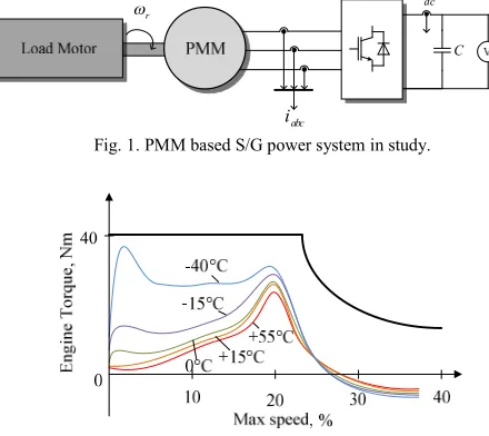
The S/G system investigated in this paper is shown in Fig. 1, whereωris the rotor speed,iabcis the three phase currents, and Cis the DC link capacitor.idcandEdcare the DC link current and voltage respectively. A surface mounted PMM is attached to a two level Active Front-End (AFE) converter. In starter mode, the PMM drives a load using electrical power from the DC bus. On the other hand, in generator mode, the load motor drives the PMM that acts as a generator to provide electrical power to the main DC link bus. It is assumed that the load motor is controlled externally, and behaves as an ideal speed source for the PMM. The S/G system was designed based on torque-speed characteristics for a typical business jet engine that can be seen in Fig. 2. It shows the torque requirements at different operating temperatures and speeds (maximum speed of 32krpm). The torque demand at -40°C is the highest for this given characteristic and the PMM was designed to meet this requirement as illustrated by the solid black line in the figure. While the engine torque characteristics can be considered, the maximum possible torque is sufficient to test the feasibility of the hybrid control scheme.
abc i
r
dc
E
dc
i
[image:2.595.309.549.299.356.2]C
Fig. 1. PMM based S/G power system in study.
[image:2.595.312.532.303.499.2]40
Fig. 2. A typical business jet engine torque-speed characteristics.
For the investigated S/G system, equations (1) and (2) indq reference frame are used as the model of the PMM:
d
d s d d q e q
di
v
R i
L
L
i
dt
(1)
q
q s q q d d m e
di
v
R i
L
L i
dt
(2)whereRsis the stator resistance,ψmis the mutual flux of the machine, andωeis the electrical speed.vd,qandid,qare the AC voltages and currents of the PMM in dq frame. Ld,q are the PMM inductances in dq frame. The derivative terms within these equations are discretised using the forward Euler method. It is assumed that the state variables remain constant during the sampling period,Ts.
( )
(
1) ( )
s
di t
i k
i k
dt
T
The discrete model of the PMM can therefore be derived as:
1
d d d
s d
d s
q e q
L i k
i k
R i k
v k
T
L
k i k
(4)
1
q q q
s q
q s
d e d m e
L i k
i k
R i k
v k
T
L
k i k
k
(5)vd,qcan be related to the switching states of the AFE,Sabc, and Edc, by the following equation if the impedance of the transmission line between the AFE and PMM is neglected:
,
( )
( )
( )
d q dc dq abc
v
k
E
k k S
k
(6)wherekdqis the dq transformation matrix where three-phase variables can be transformed todqframe:
a d dq b q cx k
x k
k
x k
x k
x k
(7)
2 2cos cos - cos
3 3
2 2
- sin - sin - - sin
3 3
2
3
dq
k k k
k k k
k
(8) [image:3.595.50.289.56.172.2]For a typical two level three-phase converter, Table 1 shows the possible switching states,Sabc, assuming an inverted pair of signals is provided to the two switches connected to each converter leg.
Table 1. Two level three-phase converter possible switching states.
i Sa Sb Sc
1 0 0 0
2 1 0 0
3 1 1 0
4 0 1 0
5 0 1 1
6 0 0 1
7 1 0 1
8 1 1 1
III. CONTROLAPPROACH
A. MPC
The inherent advantage of MPC is its ability to predict future states over a fixed set time horizon based on the measured present states and control inputs. For a power converter, this information is optimised within a cost minimisation function that determines the most suitable converter switching state for the next sampling period. Since a converter with finite switches has a finite number of switching states, the optimisation stage and the time it takes can be reduced. The process of prediction and cost minimisation recurs for every sampling period [11,
12]. A flow diagram summarising the MPC process is depicted in Fig. 3.
Fig. 3. MPC flow diagram.
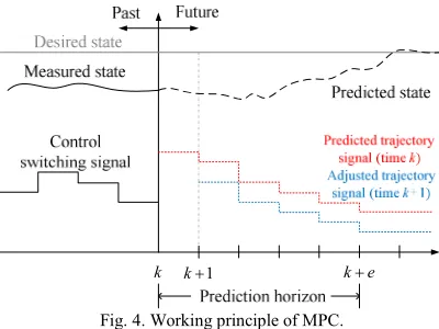
The working principle of MPC is illustrated in Fig. 4, where kis the current instant time,t, in the discrete domain andeis thee-th number of sampling steps fromk. The states of a system are measured at timek. These values are then used to predict the future switching states up to stepk+eby using the model of the system. An optimisation cost function is used over the prediction horizon to determine the optimum control signals [25]:
2 21 1
min
e e
N N
c x e e u e
e e
J
w
r
x
w
(9)whereN is the number of state variables, xe is the e-th state variable,reis thee-th reference variable, andαeis thee-th error of the predicted variables, wxeis the weighting factor for the error between the state variables to their reference, and wue is the weighting factor for the error of the predicted variables. The utilisation of the cost function forms a predicted trajectory (red) if the state values at k are used throughout the prediction horizon. However, at time instant k+ 1, if the prediction is performed with the state values at k+ 1 a more appropriate trajectory is formed (blue). In general, the greater number of steps that are performed with updated states, the more accurate the prediction. Eventually, the measured state will follow the predicted trajectory and hence reach the desired state.
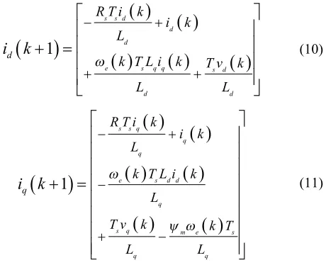
Field oriented vector control is implemented for the control of this S/G system, hence idandiqare regulated in order to produce appropriate switching signals. The prediction model of the currents are based on equations (4) and (5):
1
s s d
d d
e s q q s d
d d
d
R T i k
i k L
k T L i k T v k
L L
i k
(10)
1
s s q q q
e s d d
q
s q m e s
q q
q
R T i k i k L
k T L i k L
T v k k T
L L
i k
[image:3.595.325.555.585.772.2]k k1 k e
Fig. 4. Working principle of MPC.
Since a computational delay is always present in the practical system, the control output calculated at time instantkcan only be applied at the time instantk+1. This one sample delay can be side-stepped by predicting values two steps ahead. Equations (10) and (11) for two step prediction can be formulated as:
1 11 1 1
2
s s d
d d
e s qq s d
d d
d
R T i k
i k L
k T L i k T v k
L L
i k
(12)
1
1
1
1
1
2
1
s s q
q q
s q
e s d
q
q q
m e s
q d
R T i k
i k
L
T v k
k
T i k
i k
L
L
k
L
L
T
(13)The cost function for MPC can be formulated as:
*
2
*2
d d
MPC q q
g
i
i k
i
i k
(14) where the variables with superscript of*denote their respectivereference values. The switching state offering the least error for the cost function is selected and applied for the whole sampling period. The process then repeats starting from the variable measurement stage.
B. M2PC
Generally, M2PC has the same prediction and optimisation
pattern as MPC except with the addition of another stage for SVM. Two active voltage vectors (v1, v2) are predicted for M2PC operation instead of just one overall voltage vector. The
two active vectors are selected from all the possible adjacent vector pairs using a modified cost function that considers the current prediction and duty cycles,d0tod2. These duty cycles determine the appropriate ratio for the active and zero voltage vectors (v01,v02) within each sampling period, as shown in Fig. 5.
The active voltage vectors are calculated based on (12) and (13), and these are used to calculateiid(k+2),iiq(k+2),ijd(k+2) and ij
q(k+2). The variables with superscript i and j use switching state vectors in the order [1,2,3,4,5,6] and
[2,3,4,5,6,1] respectively. The zero vector currents, i0 d(k+2) andi0q(k+2) are calculated using (4) and (5) withvd=vq= 0, and this is used to predict v01 and v02. Since SVM is used, equation (6) can be re-arranged to give:
*
1 2
(
1)
( )
i( )
j( )
d dc d d
v k
E k d S k
d S k
(15)*
1 2
(
1)
( )
i( )
j( )
q dc q q
v k
E k d S k
d S k
(16) whered1andd2are the duty cycles forv1andv2respectively. Sid,Siq,Sjd, andSjqare the switching states indqframe. Ifvd* (k+1) andvq*(k+1) are considered as voltage references in (15) and (16), thend1andd2can be solved simultaneously:
* *
1
1
(k)
1
( )
( ) ( )
( )
( )
j j
q d d q
j i i j
dc d q d q
v k
S
v k
S k
d
E
S k S k
S k S k
(17)
* * 21
( )
1
( )
( )
( )
( )
( )
i i
q d d q
i j j i
dc d q d q
v k
S k
v
k
S k
d
E
S k S k
S k S k
(18)The zero vector currents are compared with the reference currents assuming that the predicted id(k+1) andiq(k+1) is equal toid*andiq*respectively:
1
01
*d d d
i k
i k
i
(19)
1
0
1
*q q q
i
k
i
k
i
(20)vd*(k+1) andvq*(k+1) can then be predicted to be equal to the voltage change across the inductances:
*
1
d1
dd
s
i k
L
v k
T
(21)
*
1
q1
qq
s
i k
L
v k
T
(22)The zero voltage vector duty cycle can be calculated using:
0
1
1 2d
d
d
(23)dc
E
sT
0 sd T
02v
01v
v
1v
2v
2v
1v
011 4 12
1 s
d T
2 s
d T
d T
0 sd T
0 s1 s
d T
d T
2 sa
v
bv
cv
dcE
dcE
sT
sT
1 [image:4.595.43.289.291.475.2]2 12 12 12 14
Fig. 5. M2PC typical switching pattern [18].
significant current ripples as the solutions are usually close to the switching states of the converter. In order to reduce the ripples caused by this use of predicted currents, additional weighing terms were proposed. These predicted currents are specifically for each of the active vectors, and compared with the measured current vector in order to normalise the output of the cost functions. Hence, the difference between the predicted and measured current values are considered. The two cost functions used for the prediction of the two active vectors are as follows:
* *
2 1
( )
2 2
2 ( ) 2
i i
d d q q
i i
d d q q
M PC
i i k i i k
i k i k i k i k
g
(24)
* *
2 2
( )
2 2
2 ( ) 2
j j
d d q q
j j
d d q q
M PC
i i k i i k
i k i k i k i k
g
(25)The cost function minimisation algorithm is inefficient since the duty cycles can already be calculated from the voltage references (17) and (18). However, the use of cost function provides additional flexibility in adding constraints to the vector selection algorithm. For this paper, it allows for the additional current ripple minimisation terms to be considered within the M2PC. Together with d1 andd2, the general cost
function,gM2PC, can then be formed as:
2 1 2 1 2 2 2
M P C M P C M P C
g
d g
d g
(26)The general cost function takes into consideration elements predicted one step ahead from the duty cycles and has delay compensation from the active voltage vector two step predictions.
The switching combination ofSi
d,Siq,Sjd, andSjqthat offers the smallestgM2PCwill therefore be applied in the three-phase frame with appropriate d0, d1, and d2 using the modulation scheme. The whole process for M2PC can be summarised using
a flow diagram as shown in Fig. 6. The relevant control variables are measured such as iabc, ωe, and Edc. These information can be used to predict idq(k+1) and θ (k+1).idq0 (k+1) and Δidq(k+1) can be used to predict the active voltage vectors,vdq* (k+1). After that, Sabc are converted todqframe depending on θ (k+1). For each possible switching state, the currents and duty cycles for each active voltage vector are calculated for step k+2. The overall cost function, gM2PC, determines the switching state that offers the smallest error based on the active vector cost functions and duty cycles. Finally, SVM is used to output the chosen switching state with relevant duty cycles.
[image:5.595.45.289.160.251.2]C. Control Scheme
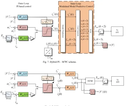
Fig. 7 shows the proposed hybrid PI-M2PC, where|V| is the
AC magnitude voltage. The control scheme can be divided into two parts; outer and inner loop. The choice of outer loop controller variables are as follows: the speed controller,Ws, is used during starter mode and switches to the DC link voltage controller, Widc, when operating in generator mode. Droop control is employed together withWidcto enable parallel source operation if required. The switch between the two outer controllers (Ws and Widc) represents the actual switch plus integrator reset logic. When operating in starter mode,Ws is connected to the inner current loop whileWidcintegrator output is set to zero. When operating in generator mode, Widc is
connected to the inner current loop and theWsintegrator output is set to zero.
The flux weakening controller, Wfw, is connected and operational for both modes to ensure control operation of the S/G system throughout the speed range by preventing converter overmodulation.iqlimis the limit for theiq*dynamic limiter that functions as part of the flux weakening control and is calculated from the maximum stator current, imax and id*. PI based controllers will be used for the outer loop and their corresponding values are in Table 2. The proportional gain of Wfwhas significant impact on the controller stability based on the studies reported in [26]. Hence, it is selected to be zero to reduce possible control instability.
The inner loops controlidandiqusing M2PC according to the current references decided by the outer loop PI controllers. The currents are predicted considering all possible switching states. The optimal voltage vectors (v1, v2, v01, v02) are selected for each sample period and is sent to the modulator to produce switching signals for the AFE.
( ),
( ),
( ), ( )
abc dc e dc
i
k E k
k i k
Measure
(
1), (
1)
dq
i k
k
Calculate
1,
2
i
j
{ , }
0 1 2
(
2), , ,
i j dq
i
k
d d d
Calculate
2 1
,
2 2M PC M PC
g
g
Calculate
1,
1
i i
j
j
Yes
2
M PC
g
Calculate
2
M PC
g
Apply switching sequence Chooseibased on smallest
6?
i
SVM
No
0
(
1),
(
1),
*(
1)
dq dq dq
i k
i k
v k
Calculate
Calculate { , }i j
(
1)
dq
S
k
[image:5.595.333.518.285.742.2]D. Electrical Angle Compensation
For drive systems that operate at high speeds, [16] stated that the prediction of the electrical angle, θ, needs to be compensated. This is becauseθis proportional to the machine rotor position,θr,and therefore there would be an error between the predicted and actual rotor position depending on the speed. To reduce this error, θr has to be compensated 1.5 sample periods ahead in order to obtain the mean rotor position after one sample delay. This can be represented by:
k 1
1 .5p r
k Ts
k (27)
IV. SIMULATIONRESULTS
The hybrid control scheme was tested using an equivalent non-linear Matlab®/Simulink® model of the S/G system. In this example, the S/G system parameters designed for the More Electric Aircraft were used in the simulation, as shown in Table 3.
The full PI control scheme designed in [27] was used as a benchmark model. This control scheme is depicted in Fig. 8. WidandWiqare the PI baseddqcurrent loops. Not shown in the figure are the decoupling terms connected to the control outputs vd(k) andvq(k). They are the last terms of equations (1) and (2) . All of the PI based controllers adopt the commonly used back calculation type anti-windup scheme. Typically, PI type controllers work based on the control variables measured at present time. If the controllers were to be tuned to be as fast as M2PC for current control (capable of following reference
within several sample periods), the AC voltage rate of change would be very high and stability cannot be guaranteed. The
[image:6.595.307.557.134.222.2]current PI controller values used for this study have been selected to achieve the fastest possible bandwidth and stability throughout the operating speed. For this S/G system, the bandwidth was selected to be 1kHz and damping ratio of 0.707 [26].
Table 2. Outer Loop Controller Parameters
Parameter Value
Wfwproportional gain 0
Wfwintegral gain 500
Wsproportional gain 50
Wsintegral gain 3000
Widcproportional gain 0.5
Widcintegral gain 200
Droop gain 8
Table 3. S/G system parameters.
Parameter Value
Stator resistance,Rs 1.058mΩ
dqframe stator inductance,Ld= Lq 99µH
Pole pairs,p 3
Magnet flux-linkage,ψm 0.03644Vs
Rated power,Prated 45kW
Combined machine and engine inertia,J 0.103kgms2
DC bus capacitance,C 1.2mF
Sampling period,Ts 62.5µs
Rated DC bus voltage,Edcrated 270V
Maximum AC current,imax 400A
Maximum torque,Tmax 40Nm
( 2)
abc
S k
1 z 1 2 ( 2) ( 2) v k v k 01 02 ( 2) ( 2) v k v k , , ( 2), ( 2) i d q j d q i k i k *( ) d i k *( ) q i k *
| |V
| |V
( ), ( )
d q
i k i k
* r r abc
i
2 2 lim max q di i i
( ) fw W z ( ) s W z 1
( 2),
( 2) d q v k v k
| |V
dc i ( ) idc W z dc E * dc i *( ) q i k *( ) d i k 1 2 ( 2) ( 2) d k d k
0( 2)
d k
Fig. 7. Hybrid PI – M2PC scheme.
( ) abc S k * d i * q i *
| |V
| |V
( ) q i k dc
i
* r r 2 2 lim max q di i i
[image:6.595.306.559.252.381.2] [image:6.595.102.515.419.769.2]( ) fw W z ( ) idc W z ( ) s W z 1 ( ) q v k
| | ( )V k
dc E * dc i 1 z ( ) id W z ( ) iq W z ( ) d
i k v kd( )
A. Control Operation
Fig. 9 shows the responses of the key state variables during operation in starter mode. The speed reference is set at 2094rad/s (20krpm). Flux weakening was operational when |V|reached its reference value ofEdcrated/√3 = 155.9V by id injection into the PMM. Both the control schemes performed satisfactorily, and were able to react to the changes in load torque,TLdue to the integral terms present in the outer loop PI controllers. Using the hybrid PI-M2PC scheme, significant
current ripple reduction was observed throughout the simulation period due to the use of M2PC as part of the control
[image:7.595.43.281.204.420.2]structure.
Fig. 9. Time domain simulation results for starter mode with impact and dispatch ofTL= 20Nm att= 0.1s and 0.3s operating at 20krpm with the full
[image:7.595.43.279.466.685.2]PI (purple) and hybrid PI-M2PC scheme (green).
Fig. 10. Time domain simulation results for generator mode operating at 20krpm between the full PI (purple) and hybrid PI-M2PC scheme (green).
The two control schemes were tested for generator mode operation as well and Fig. 10 shows the key state variable responses. During this simulation period the DC link bus was subjected to constant power load demands of 10kW, 20kW, 30kW in intervals of 0.03s. After that, they were dispatched
in the reverse order. Both control schemes were able to operate with the subjected electrical loads at 20krpm. Significant reduction in the current ripple was observed here as well when using the hybrid PI-M2PC. During the period
when the load is connected, there was some difference in the steady state forEdcand magnitude stator current,isbetween the two control schemes. This was resulted from the prediction model in the hybrid PI-M2PC becoming less
accurate as more load is added which can be considered as disturbances. The reduced current demand is compensated by the outer loop PI controllers in terms of increasedEdclevel in order to satisfy the load power requirement. Alternatively, observers can be employed within the control scheme to ensure a more accurate model prediction however this is out of the scope of this paper.
B. Parameter Variation
For model based controllers such as M2PC, it is important
to assess the robustness of the technique towards parameter changes in the power system, especially if there are no parameter observer algorithms to adapt to the changes. Parameters that could change in actual drive systems due to operating temperature or other factors such asRs,L, andC were assessed. Hence, the simulation model parameters were varied in order to check the robustness of the hybrid control scheme. Changes in thedqcurrents in terms of steady state and ripple value were observed when the parameters were varied individually. An electrical load of 5kW was used in this study to determine any current differences between load/no-load conditions.
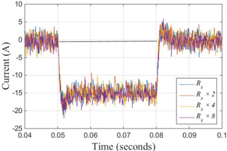
[image:7.595.316.550.476.632.2]The variation of Rs is usually based on the copper wire windings in actual electrical machines [28]. Fig. 11 shows the iq response when Rs was changed by 2, 4, and 8 times its nominal value (1.058mΩ). It can be seen that there was a small difference in steady state values that are increasing in the negative direction asiqhad to compensate for the higher Rs.
Fig. 11.iqresponses with different values ofRs.
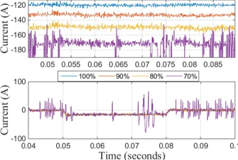
the model equations aim for AC current predictions. However, as an additional study, the variation of C has been performed to gauge the robustness of the hybrid control scheme. Fig. 13 shows iq responses to changes of C when reduced by 20% increments. The variation of C mainly affected the DC voltage controller which explains the increased underdamped transient responses. The steady state ripples increased when C was reduced below 40% of its nominal value. This could be due to the smaller sized capacitance that affects its impact as an energy storage and filter on the DC bus.
Fig. 12.id(top) andiq(bottom) responses with different values of machine
[image:8.595.326.538.295.456.2]inductance.
Fig. 13.iqresponses with different values ofC.
Fig. 14. Variation ofLdandLqat different operating frequencies (400Hz –
1600Hz).
Overall, the influence of L variation that caused the most significant effect to the hybrid PI-M2PC control performance.
A change of at least 30%Lwould be required that increases the current ripples of the S/G system and thus cause potential
instability to the hybrid control scheme. Real measurements of the machine parameters were performed at different operating frequencies (400Hz – 1600Hz to cover aircraft electrical system variable frequency range). Fig. 14 shows the maximum variation of machine inductance indqframe. It can be seen that the variation is up to 22% (nominal value ofLd= Lq = 99μH). In comparison with the worst case predicted variation range (change of L up to 30%), the practical variation falls within the stable range. Hence, parameter estimation was not considered for stable control performance.
V. EXPERIMENTRESULTS
[image:8.595.39.285.385.717.2]A small prototype of the S/G system was built to prove the usefulness of the hybrid control scheme. Fig. 15 shows the overall test rig built for this purpose. A DC machine (TT Electric, LAK 2100-A) is used as the load motor. A dedicated DC drive (Sprint Electric, PLX 10) is connected to the DC machine which controls the machine speed/torque output. The DC machine can be used to apply load torque or drive the PMM depending on starter or generator operation.
Fig. 15. Overall experimental setup.
The main machine used is a PMM (Emerson, 115UMC Series) and is powered by a two-level AFE built in-house and is controlled by a digital signal processor (DSP) (Texas Instrument, TMS320C6713 DSP Starter Kit). It is a six pole (three pole pair) machine with rated speed of 3krpm. The nominal power rating is 2.54kW and the rated torque is 8.1Nm (from 5A rated current). The relevant machine parameters can be seen in Table 4.
Table 4. Test rig parameters
Parameter Value
Rated phase voltage 230V
Machine stator resistance,Rs 1.2Ω
Machined-axis inductance,Ld 6.17mH
Machineq-axis inductance,Lq 8.379mH
Machine mutual flux,ψm 0.23Vs
Combine AC and DC machine inertia,J 0.0116kgm2
Viscous damping,B 0.0015Nms
Mechanical friction,fc 0.5372Nm
The current and voltage operational limits of the drive system are determined based on the PMM requirements. HenceEdcratedis selected as 600V for operation of this drive system. The maximum current limit,imax, is selected as 8A in order to sufficiently supply the rated current of 5A. The load demands (in terms ofiq) will therefore not normally exceed the rated current value. The AC voltage limit, |V|max, is
AFE DC Drive
PMM
[image:8.595.317.555.589.688.2]selected as 250V. These limits are chosen within the actual maximum limits with the purpose of control design verification. A sampling frequency of 12.5kHz (80µs sampling period) is selected for the control scheme.
A. Inner Current M2PC Loop
The applicability of M2PC was investigated using the test
rig. M2PC was implemented as thedq current loop control
[image:9.595.328.540.126.518.2]with the rig parameters. The control was tested with a step input of 5A for thedqcurrents and the results can be seen in Fig. 16 and Fig. 17.
Fig. 16.idcomparison between PI based (top) and M2PC (bottom)
inner current loop toid*= 5A.
Fig. 17.iqcomparison between PI based (top) and M2PC (bottom)
inner current loop toiq*= 5A.
It can be seen from the mentioned figures that a fast dynamic response was observed one sampling period after the step change was made with the M2PC current controller. As a
comparison, the PI controllers had the designed 250Hz bandwidth while the M2PC achieved 3kHz bandwidth. The
slower response (about 1kHz) for iq was due to the mechanical interaction with the load motor.
However, there is some steady state error between the reference and measureddqcurrents. This is the result of the penalisation of the current variation with respect to its previous value and the fact that M2PC does not use
integration. Another reason may be due to discrepancies between the model used for prediction and the actual system parameters. This is caused by parameter variation or voltage drop across the power switches. The steady state error is not significant and the use of outer loop PI controllers will compensate for this error. Fig. 16 and Fig. 17 also showed a comparison between the PI based inner current loops and M2PC. These results show the very fast control dynamics and
reduced current ripple that can be achieved by the use of M2PC on the S/G system.
B. Starter Operation
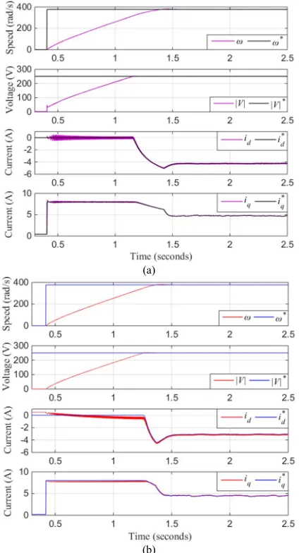
The test rig was first tested to run as a starter by using both speed and flux weakening outer loop controllers in order to provide references for the inner current loops. Fig. 18 shows the key results from the experimental S/G system in start-up mode.
(a)
(b)
Fig. 18. Start-up mode from standstill to 376.8rad/s (3.6krpm) using (a) full PI and (b) hybrid PI-M2PC.
The non-zeroiqwhile at standstill was due toTLwhich was initially applied by the DC machine. The speed controller for the PMM therefore produces an equivalent iq in order to compensate for this disturbance and maintain the speed at zero. As the speed increases due to the change in speed reference,|V|also increases but is limited at|V|max= 250V.id is demanded as a result of flux weakening in order to regulate |V|. It can be seen from Fig. 18 thatiqreduces asidincreases due to the use of the current dynamic limit. Some level of steady state error exists for thedqcurrents when the hybrid PI-M2PC is used but it is progressively reduced as the speed
increases. The cause of this error is due to the prediction model in the M2PC having less accuracy when operating with
load disturbances. WhenTLis removed as seen in Fig. 19, the steady state error ofidreduces. The steady state error ofid when operating below|V|maxis not consistent due toWfwonly responding when|V|reaches|V|max.
[image:9.595.52.274.189.521.2]the PMM was slightly less and this affected the time for the speed to reach steady state compared to the full PI control scheme.
Fig. 19 shows the same state variables whenTLdispatches. Both control schemes responded to the load change and the controlled variables are again regulated appropriately. Good dynamic performance of the hybrid PI-M2PC control for
starter mode was therefore demonstrated and verified by this test.
(a)
(b)
Fig. 19. Starter mode operating at 376.8rad/s (3.6krpm) using (a) full PI and (b) hybrid PI-M2PC.
C. Generator Operation
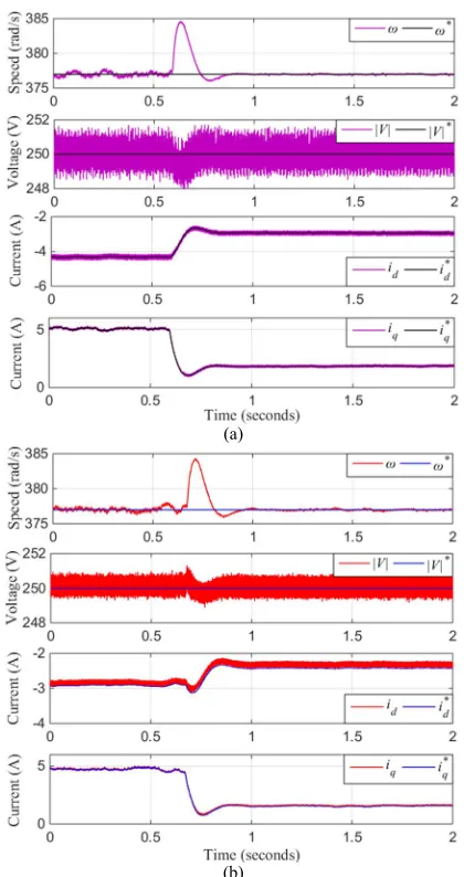
In order to perform tests in generator mode, the speed controller had to be replaced with a DC link controller. Fig. 20 shows the experimental results of the S/G system in generator mode with the flux weakening and DC link controllers as the outer loop control. A resistive load of 320Ω was connected to the DC link bus andEdcdrooped to 598V according to the droop gain in Table 2. The load was disconnected from the DC link, and the control scheme responded to the load change and regulated the controlled variables accordingly, as seen in the right side of the figure. In this case, Edc returned to 600V. The hybrid PI-M2PC scheme was also tested in generator mode. The test results can be seen in Fig. 21 that is similar to generator mode with full PI control. This experiment confirms the designed controllers are capable of maintaining stable operation of the drive system during generator mode.
[image:10.595.56.266.144.541.2]Fig. 20. Generator mode running at 387.5rad/s (3.7krpm) with load impact (left) and load dispatch (right) scenarios for the full PI control scheme.
Fig. 21. Generator mode running at 387.5rad/s (3.7krpm) with load impact (left) and load dispatch (right) scenarios for the hybrid PI-M2PC.
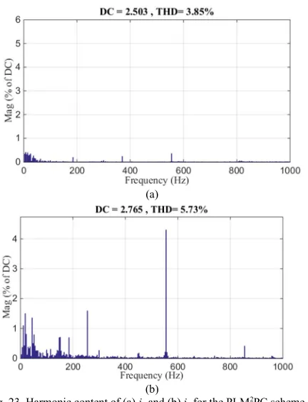
The harmonic spectrum for thedqcurrents of both control schemes shown in Fig. 20 and Fig. 21 have been produced. They are depicted in Fig. 22 and Fig. 23 respectively. The purpose is to confirm the low frequency harmonics (about 10Hz) that are present within thedqcurrents. The harmonic components for PI-M2PC was found to be lower throughout
the frequency range compared to the full PI. Similar low frequency harmonics were present within the currents, especially in iq. The hybrid PI-M2PC scheme is capable of reducing the low frequency harmonics compared to the full PI. The source of these harmonics are from the speed control of the load drive that was used to maintain the speed of the S/G operating in generator mode. The harmonics can also be reduced by changing the load drive speed control bandwidth. Current ripple reduction in terms of smaller THD has been confirmed when using the proposed hybrid PI-M2PC scheme
in comparison to the full PI control. VI. CONCLUSION
A variant of MPC, namely M2PC, was implemented in order
to assess its potential for improving the control performance
[image:10.595.314.550.284.471.2]employed for thedqcurrent control loop. The outer control loops were controlled using PI controllers. Additional weighing terms were added into the cost function in order to reduce the output current ripples. The resultant hybrid PI-M2PC scheme was found to be a suitable control alternative
for PMM based S/G system and showed improvements of reduced current ripple in comparison to the conventional full PI control scheme. Parameter variation studies indicated that the hybrid control performance was most vulnerable to the change ofLwith a change of at least 30%. Experimental work
(a)
[image:11.595.56.272.170.449.2](b)
Fig. 22. Harmonic content of (a)idand (b)iqfor the full PI control scheme
in generator mode.
(a)
(b)
Fig. 23. Harmonic content of (a)idand (b)iqfor the PI-M2PC scheme in
generator mode.
was performed to verify the application of M2PC as current
control for the PMM based S/G and as a hybrid control scheme for S/G operation. Fast dynamic response was observed with the M2PC in comparison to the PI controller
for the inner current control. Furthermore, the use of hybrid PI-M2PC showed reduced current ripples from both
simulation and experimental results. As for future works, the proposed control strategy with a suitable parameter estimation algorithm will be considered to eliminate the current steady state error. The implementation of full predictive control for the S/G system will also be analysed. Both of these studies shall be reported in future publications.
ACKNOWLEDGEMENTS
The study has be supported by Clean Sky 2 (Systems ITD), European H2020 programme.
REFERENCES
[1] H. Zhang, C. Saudemont, B. Robyns, and M. Petit, "Comparison of technical features between a More Electric Aircraft and a Hybrid Electric Vehicle," in Vehicle Power and Propulsion Conference VPPC '08. IEEE, 2008, pp. 1-6.
[2] A. Battiston, E. H. Miliani, S. Pierfederici, and F. Meibody-Tabar, "Efficiency Improvement of a Quasi-Z-Source Inverter-Fed Permanent-Magnet Synchronous Machine-Based Electric Vehicle,"IEEE Trans. Transport. Elec.,vol. 2, pp. 14-23, 2016. [3] A. Abdel-Hafez and A. J. Forsyth, "A Review of More-Electric
Aircraft," inAerospace Science and Aviation Technology ASAT-13, 2009, pp. 1-13.
[4] J. A. Rosero, J. A. Ortega, E. Aldabas, and L. Romeral, "Moving towards a more electric aircraft,"IEEE Aerosp. Electron. Syst. Mag. ,vol. 22, pp. 3-9, 2007.
[5] B. Sarlioglu and C. T. Morris, "More Electric Aircraft: Review, Challenges, and Opportunities for Commercial Transport Aircraft,"IEEE Trans. Transport. Elec.,vol. 1, pp. 54-64, 2015. [6] L. Jae Hyuk, L. Jung Hyo, P. Jin ho, and W. Chung Yuen,
"Field-weakening strategy in condition of DC-link voltage variation using on electric vehicle of IPMSM," inInternational Conference on Electrical Machines and Systems (ICEMS), 2011, pp. 1-6. [7] S. C. Carpiuc and C. Lazar, "Fast Real-Time Constrained
Predictive Current Control in Permanent Magnet Synchronous Machine-Based Automotive Traction Drives," IEEE Trans. Transport. Elec.,vol. 1, pp. 326-335, 2015.
[8] K. D. Hoang and H. K. A. Aorith, "Online Control of IPMSM Drives for Traction Applications Considering Machine Parameter and Inverter Nonlinearities,"IEEE Trans. Transport. Elec.,vol. 1, pp. 312-325, 2015.
[9] F. Gao, X. Zheng, S. Bozhko, C. I. Hill, and G. Asher, "Modal Analysis of a PMSG-Based DC Electrical Power System in the More Electric Aircraft Using Eigenvalues Sensitivity," IEEE Trans. Transport. Elec.,vol. 1, pp. 65-76, 2015.
[10] P. Wheeler and S. Bozhko, "The More Electric Aircraft: Technology and challenges," Electrification Magazine, IEEE,
vol. 2, pp. 6-12, 2014.
[11] P. Cortes, M. P. Kazmierkowski, R. M. Kennel, D. E. Quevedo, and J. Rodriguez, "Predictive Control in Power Electronics and Drives,"IEEE Trans. Inds. Elec. ,vol. 55, pp. 4312-4324, 2008. [12] J. Rodriguez, M. P. Kazmierkowski, J. R. Espinoza, P. Zanchetta,
H. Abu-Rub, H. A. Young, and C. A. Rojas, "State of the Art of Finite Control Set Model Predictive Control in Power Electronics," IEEE Trans. Inds. Info., vol. 9, pp. 1003-1016, 2013.
[13] M. Preindl and S. Bolognani, "Model Predictive Direct Speed Control with Finite Control Set of PMSM Drive Systems,"IEEE Trans. Power Elec.,vol. 28, pp. 1007-1015, 2013.
[14] M. Preindl and S. Bolognani, "Model Predictive Direct Torque Control With Finite Control Set for PMSM Drive Systems, Part 1: Maximum Torque Per Ampere Operation,"IEEE Trans. Inds. Info.,vol. 9, pp. 1912-1921, 2013.
[image:11.595.55.271.474.756.2][16] M. Hyung-Tae, K. Hyun-Soo, and Y. Myung-Joong, "A discrete-time predictive current control for PMSM,"IEEE Trans. Power Elec. ,vol. 18, pp. 464-472, 2003.
[17] X. Li and P. Shamsi, "Inductance Surface Learning for Model Predictive Current Control of Switched Reluctance Motors,"
IEEE Trans. Transport. Elec.,vol. 1, pp. 287-297, 2015. [18] L. Tarisciotti, P. Zanchetta, A. Watson, J. Clare, M. Degano, and
S. Bifaretti, "Modulated Model Predictive Control (M2PC) For A 3-Phase Active Rectifier,"IEEE Trans. Inds. App.,vol. PP, pp. 1-1, 2014.
[19] L. Tarisciotti, "Model Predictive Control for Advanced Multilevel Power Converters in Smart-Grid Applications," PhD, University of Nottingham, 2014.
[20] L. Tarisciotti, P. Zanchetta, A. Watson, J. Clare, S. Bifaretti, and M. Rivera, "A new predictive control method for cascaded multilevel converters with intrinsic modulation scheme," in
Industrial Electronics Society, IECON, 2013, pp. 5764-5769. [21] L. Tarisciotti, P. Zanchetta, A. Watson, S. Bifaretti, and J. C.
Clare, "Modulated Model Predictive Control for a Seven-Level Cascaded H-Bridge Back-to-Back Converter,"IEEE Trans. Inds. Elec.,vol. 61, pp. 5375-5383, 2014.
[22] "MIL-STD-704F," inAircraft Electric Power Characteristics, ed. United States of America: Department of Defense Interface Standard, 2014.
[23] M. Vijayagopal, L. Empringham, L. de Lillo, L. Tarisciotti, P. Zanchetta, and P. Wheeler, "Control of a direct matrix converter induction motor drive with modulated model predictive control," inEnergy Conversion Congress and Exposition (ECCE), 2015, pp. 4315-4321.
[24] S. S. Yeoh, T. Yang, L. Tarisciotti, S. Bozhko, and P. Zanchetta, "More Electric Aircraft Starter-Generator System with Utilization of Hybrid Modulated Model Predictive Control," inElectrical Systems for Aircraft, Railway, Ship Propulsion and Road Vehicles (ESARS), 2016.
[25] K. S. Holkar and L. M. Waghmare, "An Overview of Model Predictive Control,"Int. Journal of Control and Automation,vol. 3, 2010.
[26] S. Bozhko, S. S. Yeoh, F. Gao, and C. Hill, "Aircraft starter-generator system based on permanent-magnet machine fed by active front-end rectifier," in Industrial Electronics Society (IECON), 2014, pp. 2958-2964.
[27] S. S. Yeoh, F. Gao, S. Bozhko, and G. Asher, "Control design for PMM-based starter generator system for More Electric Aircraft," inPower Electronics and Applications (EPE'14-ECCE Europe), 2014, pp. 1-10.