Received 11 Nov 2013|Accepted 2 May 2014|Published 10 Jul 2014
Lasing from active optomechanical resonators
T. Czerniuk
1, C. Bru
¨ggemann
1, J. Tepper
1, S. Brodbeck
2, C. Schneider
2, M. Kamp
2,3, S. Ho
¨fling
2,3,
B.A. Glavin
4, D.R. Yakovlev
1,5, A.V. Akimov
5,6& M. Bayer
1,5Planar microcavities with distributed Bragg reflectors (DBRs) host, besides confined optical modes, also mechanical resonances due to stop bands in the phonon dispersion relation of the DBRs. These resonances have frequencies in the 10- to 100-GHz range, depending on the resonator’s optical wavelength, with quality factors exceeding 1,000. The interaction of photons and phonons in such optomechanical systems can be drastically enhanced, opening a new route towards the manipulation of light. Here we implemented active semiconducting layers into the microcavity to obtain a vertical-cavity surface-emitting laser (VCSEL). Thereby, three resonant excitations—photons, phonons and electrons—can interact strongly with each other providing modulation of the VCSEL laser emission: a picosecond strain pulse injected into the VCSEL excites long-living mechanical resonances therein. As a result, modulation of the lasing intensity at frequencies up to 40 GHz is observed. From these findings, prospective applications of active optomechanical resonators integrated into nanophotonic circuits may emerge.
DOI: 10.1038/ncomms5038 OPEN
O
ptomechanical devices are structures that host two different types of resonances: one resonance for electro-magnetic waves (photons) and another one for high-frequency mechanical vibrations (phonons). The wealth of predicted novel phenomena in these systems has attracted huge interest to them1–6. Optomechanical structures offer great flexibility of possible implementations ranging from single free-standing nanostructures (for example, spheres, toroids, cantilevers and membranes)7 to periodic arrays of these systems8–10. The size of nanostructures and the period in arrays determine the resonance frequencies of photons and phonons. For near-infrared or visible light, these dimensions have to be in the sub-micrometre range. The concomitant resonances for the phonons have frequencies in the range of 1010–1011Hz so that they could be excited and operated by picosecond acoustic techniques11.So far, experiments investigating the acoustic resonances of optomechanical devices have been performed with optically passive systems only1–10,12. A major step forward in implementing such devices into integrated optoelectronic circuits would be the extension towards active structures that can generate light. A device particularly important for telecommunication applications is the vertical-cavity surface-emitting laser (VCSEL)13. VCSELs contain optically active media (for example, semiconductor quantum wells (QWs) or quantum dots (QDs)) embedded in a planar microcavity (MC). They are excited optically or electrically in order to reach population inversion between the two electronic states involved in stimulated emission. Ideally, the energy separation between these states matches the optical cavity mode energy.
Mechanical waves in an MC with two distributed Bragg reflectors (DBRs) may be considered in a way similar to confined electromagnetic waves. Owing to the acoustic impedance mismatch in the DBR layers, stop bands emerge because of frequency splittings in the phonon dispersion at the centre and at the edges of the folded Brillouin zone scheme8,14,15. Two types of mechanical resonances may exist in such resonators: strongly localized MC phonon modes within the DBR stop bands that arise from the imperfection of the DBR periodicity introduced by the central cavity layer, and DBR resonances with a large density of states at the edges of the stop bands. Following the acousto-optical studies by Fainstein et al.8 on a passive MC, ideas of exploring and exploiting the optomechanical properties of VCSELs have been around for some time16; however, so far, the interplay of the two different types of resonances was neither experimentally nor theoretically investigated for VCSELs in active lasing operation. Recent experimental work17 demonstrated efficient modulation of the laser output by picosecond acoustic pulses but showed no sign of involvement of optomechanical harmonic resonances.
Particularly challenging in studying the impact of optomecha-nical VCSEL resonances is the understanding of the phonon interaction processes with the optically active medium. Many different relevant processes have to be taken into account, and in general the lasing dynamics is nonlinear and may involve competing resonator modes18. To develop such understanding requires a large-scale effort. However, before starting such an extensive effort, its value should be evidenced by demonstrating that the dual resonances in active optomechanical devices such as VCSELs do indeed have a significant impact on the lasing output—the present work answers this question favourably.
Here we demonstrate the results of picosecond acoustic experiments carried out on two VCSELs, for which we have chosen on purpose very different designs to highlight the potential of our approach. Besides their different compositions, the VCSELs were operated at different temperatures applying
varying optical excitation conditions, which further highlights the versatility of our method. The main result is observation of long-living and high-amplitude harmonic oscillations in the lasing output because of excitation of mechanical VCSEL resonances.
Results
Experiment and nanomechanical properties of the structures. The experiment is shown schematically in Fig. 1a. Light emission from the optically active media in the VCSELs is the result of continuous or pulsed laser excitation while the coherent phonons are excited remotely by injection of strain pulses from the VCSEL substrate. The strong impact of resonant phonons is evidenced by a pronounced ringing of the laser emission, which continues for nanoseconds long after the original broadband picosecond strain pulse has left the active region of the VCSEL.
The two VCSELs were based on GaAs/AlAs material, with the first one (VCSEL1) containing 12 QW layers distributed over three stacks and the second one (VCSEL2) containing a single QD layer only. These optically active layers were placed in the electric field antinodes of the central cavity layer or the adjacent layers, sandwiched between the DBRs, as shown in Fig. 1a. Figure 1b shows calculations of the phonon dispersion relations of the DBRs in these two samples, with the close-ups highlighting the band gap regions. At these band gaps, the phonon group velocity tends to be zero, corresponding to particularly long-living phonons inside the cavities. The coherent phonon wavepacket in form of a broadband picosecond strain pulse e0(zvt) with
s¼4.8103m s1 being the longitudinal sound velocity in GaAs, is generated in a 100-nm-thick Al film deposited on the GaAs substrate opposite to the cavity19, as shown schematically in Fig. 1a. Following injection into the VCSEL, the strain pulse propagates sequentially through bottom DBR, MC layer and finally top DBR. After reflection at the surface the strain pulse passes again through these layers in reversed order. During propagation it undergoes a spatiotemporal transformation because of the multiple reflections at the interfaces of the multilayered structure. The temporal strain profiles, calculated by the transfer matrix formalism at the position of the central cavity layer in the two VCSELs, are shown in Fig. 1c. In the time window when the strain pulse is outside, still a nanosecond tail is present in this layer because of the mechanical VCSEL resonances that have been excited by the acoustic pulse. The corresponding Fourier spectra are shown in the inset of Fig. 1c, demonstrating clearly the excitation of resonant modes with frequencies coinciding with the band edges in the phonon dispersion.
In our particular experiments, it is important that VCSELs host two kinds of acoustic resonances: (1) strongly localized phonon resonances with energies in the DBR stop bands that arise from the imperfection introduced into the DBR periodicity by the central cavity layers and (2) DBR resonances with a large density of states at the edges of the stop bands, namely at the centre and at the edges of the Brillouin zone with phonon wave numbers
that are there are either very narrow, such as in VCSEL1, or completely closed, such as in VCSEL2 (see Fig. 1b). Thus, experimental spectra of VCSEL1 show only a single line at the corresponding stop band because the DBR modes and the cavity mode cannot be resolved separately.
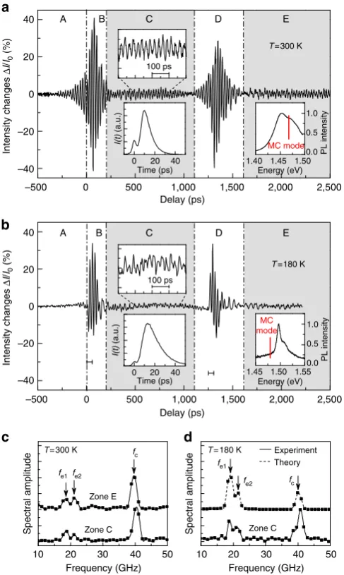
Lasing from the cavity with QWs. VCSEL1 was excited by femtosecond pulses originating from the same laser as used for strain pulse generation. The temporal shape of the resulting VCSEL emission pulsesI(t) was measured by a streak camera and is shown in the insets of Fig. 2. The duration of the emission pulses is several tens of picoseconds, which is much shorter than the spontaneous emission lifetime of carriers (B1 ns) in the studied VCSEL1. In the experiments with picosecond short emission pulses, the time-integrated intensity was measured by a photodiode as function of the delay t between the optical excitation of the laser emission and the picosecond strain pulse injection. We present here data recorded for an excitation far above the laser threshold. Figure 2 shows the measured signal
DI(t)/I0(I0is the signal in absence of the strain pulse) in the delay time interval when the strain pulse is travelling through the VCSEL. Figure 2a,b shows the measurements atT¼300 K, room temperature and at T¼180 K, respectively. By this temperature change, the QW emission is considerably shifted relative to the cavity mode, as seen from the lower right-hand insets in Fig. 2. These show the spontaneous emission spectra recorded from the edge of VCSEL1. The corresponding temporal evolutionsI(t) of the laser output pulses are given in the lower left-hand insets.
The intensity modulations DI(t)/I0 in Fig. 2a,b show prominent oscillations for whose assignment several time ranges, labelled A–E, are indicated with their borders shown by the vertical dash-dotted lines. These time ranges are defined by the momentary position of the broadband picosecond strain pulse. Maximum amplitude of the oscillations occurs in ranges B and D when the leading edges of the strain pulses pass the QWs in forward and backward directions, respectively, as highlighted also by the horizontal bars in Fig. 2b. Smaller amplitude oscillations of
DI(t)/I0are observed in the C and E ranges when the tail of the coherent phonon pulse initiated by the DBR is present in the cavity layer with the QWs. The Fourier spectra of DI(t)/I0 in these ranges in Fig. 2c,d exhibit several distinct resonance peaks. Most strikingly, these resonances coincide with the calculated frequencies for the zone-edge (fe1, fe2) and zone-centre (fc) resonant phonons with long cavity lifetimes because of their small group velocity in VCSEL1 (compare Fig. 2c,d with the inset in Fig. 1c). This excellent agreement between measured and calculated frequencies demonstrates that the laser emission is modulated by the resonant phonons of the active optomechanical device.
Lasing from the cavity with QDs. Our interpretation is corro-borated by the results obtained for VCSEL2, which was optically excited by a continuous wave laser with a wavelength of 532 nm. Here the impact of the picosecond strain pulses was monitored in real time by measuringI(t) with a streak camera, again well above the lasing threshold. For this sample, a temperature ofT¼10 K was chosen to have a vanishing detuning between the cavity mode atEc2¼1.351 eV and the QD emission and to obtain a low-lasing threshold (inset in Fig. 3a). The measured temporal evolution
DI(t)/I0of the modulation enforced by the incident strain pulse is shown in Fig. 3a. The modulation peak around time zero does not exploit the phonon band structure of the DBRs but can be understood by considering the VCSEL as an elastic continuum as discussed in earlier work17. The striking novel feature of interest here is the pronounced, long-lasting oscillating tail in I(t) extended over 550 ps. The Fourier spectrum of this tail is shown in Fig. 3b and it consists of a single resonant peak at 17.2 GHz, corresponding to the DBR zone-edge phonon around the stop band of VCSEL2 (compare with calculated spectrum in Fig. 1b). However, the splitting of 2.2 GHz between the lower and the higher energy DBR resonance at the band edges is not
VCSEL1 VCSEL2
VCSEL1
Frequency (GHz)
VCSEL2
1.00 0.95
1 0
0.0 0.5
Wave number (/D) 10
20 30 40
Frequency (GHz)
0
Wave number (/D)
0.5 10
10 20 30 40
Frequency (GHz)
0.95 1.00 19 20 21
39 0.05 0.00
40 41
16 17 18
19 0.00 0.05
34 35 36 37
0 10 20 30 40 50
Spectral amplitude
0
Time (ps)
500 1,000
–4 –2 0 2 4
Strain (a.u.)
Cavity Cavity
Aluminium
Active area
VCSEL1: quantum wells
QDs
DBR DBR
VCSEL2: quantum dots Strain
Emission Excitatio
n
4 QWs 4 QWs 4 QWs
fe1
fe2
fe1 fe2 fc
[image:3.595.48.290.48.443.2]resolvable within the lifetime of the oscillations, which yields a frequency resolution of 3.8 GHz. In addition, the lasing emission from VCSEL2 shows clear fingerprints of optomechanical
resonances, similar to VCSEL1. The absence of the peak corresponding to the zone centre in VCSEL2 is because of the acoustic matching in the DBR layers that results in the vanishing of the phonon stop band at the Brillouin zone centre (see Fig. 1b).
Discussion
Here we discuss the mechanisms responsible for modulating the laser emission by coherent phonons. We consider two major contributions: (1) modulation of the gain spectrum of QWs and QDs in VCSEL1 and VCSEL2, respectively, and (2) switching between different optical laser modes in VCSEL1.
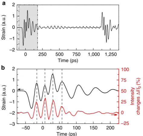
We use the deformation potential model to analyse the gain modulation and compare the results of the calculations with the signal measured in VCSEL1 at T¼180 K. In this case, the electron-hole transition is centred atEQW¼1,497 meV with a full
width at half maximum of B15 meV. In absence of the strain pulse, the cavity mode is detuned by 20 meV to lower energies. The dynamical strain changes the energy of the electron-hole transitions in the QWs, thereby modulating the detuning of the gain profile of the active medium relative to the MC optical resonance mode. The energy shift of the gain profile follows the shift of the band gap of GaAsdEQW¼Xe(with the deformation potentialXB10 eV). Thus, the gain decreases or increases for the compressive (eo0) or tensile parts (e40) of the strain pulse, respectively. The gain medium consists of 12 QWs located in the cavity layer and the first layers of the DBRs. Thus, the net effect of the gain modulation is given by the sum of the contributions to the gain from the individual QWs. Figure 4a shows the calculated strain evolution for a 1.5-ns time window, showing two similar sequential strain sequences corresponding to the incoming and the reflected components. The black line in Fig. 4b shows a close-up of the strain corresponding to the leading part of the incident strain pulse passing the active medium. Assuming that the gain is proportional to dEQW, which is true for eoB104, this evolution can be compared directly to the intensity changes in experiment, shown by the red curve. Sequence and phase of the
0 500 1,000
Delay (ps)
1,500 2,000 2,500
A B C D E
0 20
Time (ps) 40
I(t)
(a.u.)
1.40 1.45 1.50
Energy (eV) 1.0
0.5
0.0 PL intensity
0
–500 500 1,000 1,500 2,000 2,500
–20
–40 0 20 40 –20
–40
–500 0 20 40
A B C D E
Intensity changes
Δ
I
/
I0
(%)
Intensity changes
Δ
I
/
I0
(%)
Delay (ps)
0 20
Time (ps) 40
I(t)
(a.u.)
10 20
Frequency (GHz)
30 40 50 10 20
Frequency (GHz)
30 40 50
fc
T=300 K
Zone C
Spectral amplitude
Zone E
fe2
fe1
1.45 1.50 Energy (eV)
1.55 0.0 PL intensity
Experiment Theory
Spectral amplitude Zone C
fe2
fe1
T= 180 K
fc
100 ps
MC
mode 1.0
0.5
T=180 K
100 ps
MC mode
[image:4.595.46.290.48.456.2] [image:4.595.307.550.50.204.2]T=300 K
Figure 2 | Modulation of the lasing output in VCSEL1.(a,b) Time-integrated lasing output as function of the delay between laser cavity and strain pulse excitations measured for VCSEL1 atT¼300 K (a) and 180 K (b). The vertical dash-dotted lines indicate the borders between the temporal zones A–E. Zones C and E correspond to the ranges in which long-living resonant phonons of the active optomechanical device persist in the cavity layer containing the optically active medium. Close-ups of the temporal evolutions of the oscillating signals are shown in the upper insets in zone C. The lower insets in zone C show the time evolutions of the laser pulses; the small peak at the beginning corresponds to the optical excitation of the VCSEL1. The right insets in zone E show the spectral position of the MC optical modes relative to the PL spectrum, measured from the side of the VCSEL. (c,d) Fourier spectra (squares) obtained from the temporal evolutions in zones C and E shown ina,b, respectively. Their interpolations (solid curves) show peaks that are in excellent agreement with the resonant frequencies of the zone-edge (fe1andfe2) and zone-centre (fc) phonons in VCSEL1. The slight difference in frequencies (0.5 GHz) for zones C and E in c, observed also in the theoretical spectra, is related to the asymmetric design of the two DBRs surrounding the central cavity. The dotted curve in dis the calculated spectrum assuming the deformation potential mechanism for the strain-induced modulation of the lasing output from the 12 active QWs in VCSEL1.
0.0 0.5 1.0
0 0
–100 100 200 300 400
10
Frequency (GHz) 40 30 20
Emission intensity
Intensity changes
Δ
I
/
I0
(%)
T=10 K
Spectral amplitude
500 Time (ps)
1,000 Energy (eV)
1.34 1.36
Cavity mode
QDs
peaks show good agreement between experiment and theory. The calculated Fourier spectrum of the oscillating tail is shown in Fig. 2d by the dotted curve. Reasonable agreement is also obtained for VCSEL2, for which the inhomogeneous distribution of exciton resonances in the QDs20was included in the analysis of the deformation potential mechanism. The calculated amplitude spectrum is shown in Fig. 3b by the dashed line along with the experimental Fourier transform as solid line.
However, the deformation potential model cannot explain the modulation occurring for VCSEL1 in time range A before the strain pulse reaches the QWs, most prominent at 300 K (see Fig. 2a). In this interval, the strain pulse is travelling through the first DBR so that it cannot modulate the spectral profile of the QW gain medium. Here most likely the phonons modulate the optical mode distribution of the laser emission18.
In conclusion, our experiments evidence the interplay of the optical and acoustic dual resonance properties of VCSEL devices operated in the lasing regime, resulting in an emission modulation by resonant coherent phonons at 40 GHz frequency, even at room temperature. The modulation amplitude reaches significant values: up to 4% in VCSEL1 and 50% in VCSEL2. The wealth of underlying mechanisms (deformation potential coupling, optical mode switching and so on) offers a variety of tools for controlling the light emission, depending on the specific design of the active optomechanical device.
We want to emphasize that active optomechanical resonators are not limited to applications such as modulation of laser emission, which may be achieved also by other established techniques21. We rather believe that our study marks the starting point of using such devices also in nanophotonic circuits. Compared with passive devices, the interaction between
photons and phonons can be strongly increased because of the electron–phonon interaction in the active medium. Thereby, concepts of exploiting passive optomechanical devices in quantum computing and information technologies, widely discussed nowadays1–8,12, may be extended and amplified by embedding active optomechanical resonators into integrated photonic circuits. Nanomechanical control of single photon generation in microcavities containing a single QD is one prospective application of these resonators in quantum optical circuits. It is challenging to operate integrated circuits optomechanically as long as the strain pulse generation is based on femtosecond laser sources. However, besides the fact that nanophotonic elements with integrated microlasers are already produced industrially (for example, see http://www.oclaro.com/ solutions-100G.php), the generation of acoustic waves using electrical techniques (without external lasers) becomes feasible nowadays in semiconductor nanostructures22,23.
There is another appealing application field of active optomechanical devices that concerns novel techniques for generation of coherent sub-THz phonons. Excitation of pulsed microlasers such as VCSELs pumped with electrical current will provide optical excitation inside the optomechanical cavity, thus generating coherent phonons at the resonance frequencies of the mechanical resonator without massive external pulsed optical sources. A further concept, widely discussed by now, is based on bringing passive optomechanical resonators into the regime of parametric instability leading as well to the generation of coherent phonons24–27. In passive resonators, this generation is based on the photon pressure effect. By implementing electrons in the optomechanical system the electron–phonon interaction becomes additionally involved so that parametric generation of coherent phonons in the sub-THz frequency range may become more realistic than in passive devices. Implementation of these challenging tasks and insertion of active optomechanical resonators into complex integrated electronic and photonic circuits will allow one to explore high-frequency sound as miniature analogue of acoustic devices in traditional electronics and optics.
Methods
Samples and lasing parameters.Both devices were grown by molecular-beam epitaxy on n-doped [001]-oriented GaAs substrates. Three groups of 12-nm-wide GaAs QWs form the active region of VCSEL1. Each group consists of four QWs separated from each other by 4-nm-wide AlAs barriers. The middle group is located in the centre of thel/2-cavity, while the outer QW sets are placed in the first DBR layers, where the photon field has an antinode, as shown in Fig. 1a. The DBRs are built out of 58-nm-wide Al0.2Ga0.8As and 67-nm-wide AlAs double layers corresponding tol/4 optical thickness (27 and 23 periods in the bottom and top reflectors, respectively). The Q-factorB104of the optical cavity was deduced
from the calculated reflectivity spectrum and confirmed by local micro-photoluminescence studies at 10 K. In order to obtain the spectrum of the gain medium unfiltered by the MC, the QW photoluminescence was collected from the side of the sample. For excitation of VCSEL1, laser pulses from a Ti:sapphire oscillator were used (800-nm centre wavelength, 140-fs pulse duration and 100-kHz repetition rate). At room temperature, the lasing threshold is crossed at 600mJ cm2. AtT¼180 K, the threshold increases significantly to 1,600mJ cm2
because of the narrowing of the spectral profile of the electron-hole transition and its high-energy shift relative to the cavity mode (see the right inset in Fig. 2b). The angular aperture of the detection was about 2°, smaller than the beam divergence of common VCSELs28.
The DBR stacks sandwiching the GaAslcavity layer of VCSEL2 are composed of alternating 67-nm-wide GaAs and 80-nm-wide AlAs double layers (27 pairs at the bottom, 23 pairs at the top). A single sheet of In0.3Ga0.7As QDs in the centre of the cavity layer acts as active region, see Fig. 1a. The ensemble is inhomogeneously broadened with a spectral width of 11 meV atT¼10 K, much more than the cavity mode linewidth of 1.2 meV, which results in an inefficient coupling. VCSEL2 is optically excited using a Q-switched Nd:YAG laser emitting 23-ns pulses at 532 nm. The excitation pulse duration is much longer than the laser emission dynamics, so that the lasing intensity follows adiabatically and may be treated as stationary. At a peak excitation power density of 22 kW cm2, the lasing threshold
is crossed.
0 –50
Time (ps) 100
50 150 200
–3 0
–1
–2 1 2
Strain (a.u.)
–25 0 25 50 75 100
Intensity
changes
Δ
I
/
I0
(%)
0 250 500 750 1,000 1,250
–2 –1 0 1 2
Time (ps)
[image:5.595.49.286.48.274.2]Strain (a.u.)
Generation of picosecond strain pulses.A 100-nm-thick aluminium film was deposited on the GaAs substrate opposite to the MC. For generation of the strain pulses, it is illuminated by laser pulses from the same Ti-sapphire laser used for pushing VCSEL1 into lasing. The energy density per pulse isB10 mJ cm2,
resulting in injection of a strain pulse (schematically shown in Fig. 1a) with amplitude ofB103and duration ofB10 ps19.
References
1. Wiederhecker, G. S., Brenn, A., Fragnito, H. L. & Russell, P. St. J. Csoherent control of ultrahigh-frequency acoustic resonances in photonic crystal fibers. Phys. Rev. Lett.100,203903 (2008).
2. Weis, S.et al.Optomechanically induced transparency.Science330,1520–1523 (2010).
3. Lin, Q.et al.Coherent mixing of mechanical excitations in nano-optomechanical structures.Nat. Photonics4,236–242 (2010). 4. Arcizet, O., Cohadon, P.-F., Briant, T., Pinard, M. & Heidmann, A.
Radiation-pressure cooling and optomechanical instability of a micromirror. Nature444,71–74 (2006).
5. Teufel, J. D.et al.Sideband cooling of micromechanical motion to the quantum ground state.Nature475,359–363 (2011).
6. Chan, J.et al.Laser cooling of a nanomechanical oscillator into its quantum ground state.Nature478,89–92 (2011).
7. Aspelmeyer, M., Kippenberg, T. J. & Marquardt, F. Cavity Optomechanics. Preprint at http://arxiv.org/abs/1303.0733 (2013).
8. Fainstein, A., Lanzillotti-Kimura, N. D., Jusserand, B. & Perrin, B. Strong optical-mechanical coupling in a vertical GaAs/AlAs microcavity for subterahertz phonons and near-infrared light.Phys. Rev. Lett.110,037403 (2013). 9. Akimov, A. V.et al.Hypersonic modulation of light in three-dimensional
photonic and phononic band gap materials.Phys. Rev. Lett.101,033902 (2008). 10. Pennec, Y.et al.Simultaneous existence of phononic and photonic band gaps in
periodic crystal slabs.Opt. Express18,14301–14310 (2010).
11. Thomsen, C., Grahn, H. T., Maris, H. J. & Tauc, J. Surface generation and detection of phonons by picosecond light pulses.Phys. Rev. B34,4129–4138 (1986).
12. Gro¨blacher, S., Hammerer, K., Vanner, M. R. & Aspelmeyer, M. Observation of strong coupling between a micromechanical resonator and an optical cavity field.Nature460,724–727 (2009).
13. Iga, K., Koyama, F. & Kinoshita, S. Surface emitting semiconductor lasers.IEEE J. Quantum Electron.24,1845–1855 (1988).
14. Colvard, C., Merlin, R., Klein, M. V. & Gossard, A. C. Observation of folded acoustic phonons in a semiconductor superlattice.Phys. Rev. Lett.45,298–301 (1980).
15. Jusserand, B., Paquet, D., Mollot, F., Alexandre, F. & Le Roux, G. Influence of the supercell structure on the folded acoustical Raman line intensities in superlattices.Phys. Rev. B35,2808–2817 (1987).
16. Le´ger, Y. Double magic coincidence in an optomechanical laser cavity.Physics
6,6 (2013).
17. Bru¨ggemann, C.et al.Laser mode feeding by shaking quantum dots in a planar microcavity.Nat. Photonics6,30–34 (2012).
18. Chang-Hasnainet al.Dynamic, polarization, and transverse mode characteristics of vertical cavity surface emitting lasers.IEEE J. Quantum Electron.27,1402–1409 (1991).
19. Tas, G. & Maris, H. J. Electron diffusion in metals studied by picosecond ultrasonics.Phys. Rev. B49,15046–15054 (1994).
20. Bru¨ggemann, C.High Frequency Acousto-optics in Semiconductor and Metal Nanostructures. PhD thesis, Technische Uni. Dortmund (2013).
21. Deryagin, A. G., Kuksenkov, D. V., Kuchinskii, V. I., Portnoi, E. L. & Khrushchev, I. Y. Generation of 110 GHz train of subpicosecond pulses in 1.535mm spectral region by passively modelocked InGaAsP/InP laser diodes. Electron. Lett.30,309–311 (1994).
22. Maryam, W., Akimov, A. V., Campion, R. P. & Kent, A. J. Dynamics of a vertical cavity quantum cascade phonon laser structure.Nat. Commun.4,2184 (2013).
23. Mahboob, I., Nishiguchi, K., Fujiwara, A. & Yamaguchi, H. Phonon lasing in an electromechanical resonator.Phys. Rev. Lett.110,127202 (2013).
24. Grudinin, I. S., Lee, H., Painter, O. & Vahala, K. J. Phonon laser action in a tunable two-level system.Phys. Rev. Lett.104,083901 (2010).
25. Braginsky, V. B., Strigin, S. E. & Vyatchanin, S. P. Parametric oscillatory instability in Fabry–Perot interferometer.Phys. Lett. A287,331–338 (2001). 26. Zhao, C.et al.Three-mode optoacoustic parametric amplifier: a
tool for macroscopic quantum experiments.Phys. Rev. Lett.102,243902 (2009).
27. Kippenberg, T. J., Rokhsari, H., Carmon, T., Scherer, A. & Vahala, K. J. Analysis of radiation-pressure induced mechanical oscillation of an optical microcavity. Phys. Rev. Lett.95,033901 (2005).
28. Zhao, Y.-G.et al.Far-field and beam characteristics of vertical-cavity surface-emitting lasers.Appl. Phys. Lett.69,1829–1831 (1996).
Acknowledgements
This study was funded by the Deutsche Forschungsgemeinschaft (project BA 1549/14-1), the State of Bavaria and the Ukrainian State Fund for Fundamental Researches (programme SFFR-DFG). A.V.A. also acknowledges financial support by the Alexander von Humboldt Foundation. M.B. acknowledges partial financial support from the Rus-sian Ministry of Science and Education (contract No.14.Z50.31.0021).
Author contributions
A.V.A., D.R.Y. and M.B. developed the idea for the experiment; T.C., C.B., J.T. and A.V.A. performed the experiment; T.C. and C.B. processed the data and performed the calculations; T.C., C.B., A.V.A. and M.B. analysed the data and wrote the manuscript; S.B., C.S., M.K. and S.H. fabricated the samples; B.A.G. provided theoretical support.
Additional information
Competing financial interests:The authors declare no competing financial interests.
Reprints and permissioninformation is available online at http://npg.nature.com/ reprintsandpermissions/
How to cite this article:Czerniuk, T.et al.Lasing from active optomechanical resonators.Nat. Commun.5:4038 doi: 10.1038/ncomms5038 (2014).