Virtual network functions orchestration in wireless
networks
Roberto Riggio, Abbas Bradai, Tinku Rasheed, Julius Schulz-Zander,
Slawomir Kuklinski, Toufik Ahmed
To cite this version:
Roberto Riggio, Abbas Bradai, Tinku Rasheed, Julius Schulz-Zander, Slawomir Kuklinski, et
al.. Virtual network functions orchestration in wireless networks. CNSM 2015 11th
Interna-tional Conference on Network and Service Management, Nov 2015, Barcelone, Spain.
pp.108-116, 2015, 2015 11th International Conference on Network and Service Management (CNSM).
<
10.1109/CNSM.2015.7367346
>
.
<
hal-01292221
>
HAL Id: hal-01292221
https://hal.archives-ouvertes.fr/hal-01292221
Submitted on 22 Mar 2016
HAL
is a multi-disciplinary open access
archive for the deposit and dissemination of
sci-entific research documents, whether they are
pub-lished or not.
The documents may come from
teaching and research institutions in France or
abroad, or from public or private research centers.
L’archive ouverte pluridisciplinaire
HAL
, est
destin´
ee au d´
epˆ
ot et `
a la diffusion de documents
scientifiques de niveau recherche, publi´
es ou non,
´
emanant des ´
etablissements d’enseignement et de
recherche fran¸
cais ou ´
etrangers, des laboratoires
publics ou priv´
es.
Virtual Network Functions Orchestration in
Wireless Networks
Roberto Riggio
∗, Abbas Bradai
§, Tinku Rasheed
∗, Julius Schulz–Zander
†, Slawomir Kuklinski
‡, Toufik Ahmed
¶∗CREATE-NET, Italy; Email: rriggio,[email protected]
§XLIM Institute, University of Poitiers, France; Email: [email protected] †TU-Berlin, Berlin, Germany; Email: [email protected]
‡Orange Polska, Warsaw, Poland; Email: [email protected] ¶CNRS-LaBRI, University of Bordeaux, France; Email: [email protected]
Abstract—Network Function Virtualization (NFV) is emerging as one of the most innovative concepts in the networking landscape. By migrating network functions from dedicated mid-dleboxes to general purpose computing platforms, NFV can effectively reduce the cost to deploy and to operate large networks. However, in order to achieve its full potential, NFV needs to encompass also the radio access network allowing Mobile Virtual Network Operators to deploy custom resource allocation solutions within their virtual radio nodes. Such requirement raises several challenges in terms of performance isolation and resource provisioning. In this work we formalize the Virtual Network Function (VNF) placement problem for radio access networks as an integer linear programming problem and we propose a VNF placement heuristic. Moreover, we also present a proof–of–concept implementation of an NFV management and orchestration framework for Enterprise WLANs. The proposed architecture builds upon a programmable network fabric where pure forwarding nodes are mixed with radio and packet process-ing nodes leveragprocess-ing on general computprocess-ing platforms.
I. INTRODUCTION
Network Function Virtualization (NFV) promises to reduce the cost to deploy and operate large networks by migrating network functions from dedicated hardware appliances to software instances running on general purpose virtualized networking and computing infrastructures. This in time shall improve the flexibility and the scalability of the mobile net-work in that the deployment of new features and services will be quicker (software vs hardware life–cycles) and different network functions can share the same computing resources paving the way to further economies of scale. However an ef-fective management and orchestration framework is needed if the virtual resources made available by the NFV Infrastructure are to be used efficiently.
In this work, we set to investigate the concept of VNF management and orchestration in the radio access network (RAN) domain. In this scenario we expect mobile virtual network operators (MVNO) to specify their requests in terms of a chain, or a graph, of VNFs. Such VNF chain can include functions such as load–balacing and firewall, as well as virtual radio nodes. The latter type of components, i.e. virtual radio nodes, imposes several requirements. MVNOs must be allowed to deploy custom resource allocation schemes
within their virtual radio nodes while the system shall both
enforce strict performance isolation between MVNOs and ensure efficient resource utilization across the network.
This paper extends our previous work [1] by: (i) formal-izing the Virtual Network Function placement problem for radio access networks as an integer linear programming (ILP) problem; and (ii) proposing a new scalable VNF placement heuristic. Moreover, we report on a updated proof–of–concept VNF management and orchestration framework for enterprise WLANs and on the implementation and evaluation of a few VNFs. To the best of the authors knowledge, this is the first attempt at providing a formulation of the VNF placement prob-lem for radio access networks in such a way that performance isolation between multiple MVNOs is accounted for from the resource request phase.
The reminder of this paper is structured as follows. In Sec. II we discuss the related work. The physical network model, the VNF request model, and ILP problem formulation are presented in Sec. III. The VNF placement heuristic and its evaluation are presented in, respectively, in Sec IV and in Sec. V. The proof–of–concept is presented in Sec VI while a few sample VNFs and their evaluation are presented in Sec. VII Finally, Sec. VIII draws the conclusions pointing out the future work.
II. RELATEDWORK
The recent advances in general purpose computing plat-forms paved the way to a new generation of software routers. However, many of these solutions focus on improving the pure raw packet processing speed [2], [3], [4] but do not tackle the problem of deploying and orchestrating VNFs. In parallel there are significant efforts toward VNF management and orchestra-tion. In particular the European Telecommunications Standards Institute (ETSI) has recently tackled the NFV concept [5] while the OPNFV project [6] and the MANO [7] are working toward an open source carrier grade platform for NFV. - Virtual Network Embedding: The amount of literature on virtual network embedding (VNE) topic is considerable. Seminal works in this domain include VINEYard [8] for single domain VNE and PolyVINE [9] for multi–domain VNE. For a comprehensive survey on VNE algorithms we point the reader to [10]. However, to the best of the authors knowledge, none of these works formulate the VNE problem for hybrid wired/wireless networks with the goal of ensuring performance isolation between tenants.
- VNF Placement: The VNF placement problem is con-ceptually similar to component placement in data–centers and clouds. The amount of literature in this domain is thus humbling [11], [12], [13]. In [11] the authors study the problem of placing virtual machine instances on physical containers in such a way to reduce communication overhead and latency. In [12] the author propose a novel design for a scalable hierarchical application components placement for cloud resource allocation. The proposed solution operates in a distributed fashion, ensuring scalability, while providing performances very close to that of the centralized algorithm. This work is extended in [13] where several algorithms for efficient data management of component-based applications in cloud environments are proposed. A survey on resource management in cloud computing environments can be found in [14]. In [15] a joint node and link mapping algorithm is proposed. While the authors of [16], [17] tackle the problem of dynamic VNF placement. Targeting resource allocation in data-centers, these works do not tackle the problem of virtualized radio function placement.
- Wireless & Mobile Networks:The topic of radio resources virtualization has received significant attention in the literature. In [18], a WLAN virtualization approach namedVirtual WiFi
is proposed extending the virtual network embedding from the wired to the wireless domain. Kernel–based virtual machines are used as a virtual wireless LAN devices. Time domain multiplexing is used in order to provide isolation between the virtual wireless devices. In [19], [20], wireless network virtualization is applied to wireless mesh networks. A virtual network traffic shaper is introduced in [21], [22] for air time fairness in 802.16e networks. In [23], [24] the problem of virtualizing OFDMA–based wireless networks (i.e. WiMAX and LTE) is studied. The authors tackle the problem both at the radio and the core network level opening the way to interesting infrastructure sharing scenarios. Similar consideration can be also made for [25] where a framework for sharing a single WiMAX base station is proposed. Wireless Virtualization of 802.11 devices is the focus of [26]. In all the cases above, however, the channel–aware placement of VNFs over radio
andwired resources is not formulated nor is the performance
isolation challenge between multiple MVNOs tackled. III. NETWORKMODEL
In the VNF placement problem the input consists of Service Function Chains (SFC) consisting of a variable number of VNFs, whereas the substrate network, called Network Func-tion VirtualizaFunc-tion Infrastructure (NFVI), provides the physical constraints in terms of bandwidth and capacity. In this context the term capacity is not related only to pure computational resources, such as number of CPU cores and memory, instead it refers also to packet forwarding and radio processing capa-bilities. Before introducing the proposed solution we need to detail specific notations for the NFVI and the SFC requests.
A. Network Function Virtualization Infrastructure Model
Let Gnf vi= (Nnf vi, Enf vi)be a directed graph modeling
the physical network, where Nnf vi is the set ofn=|Nnf vi|
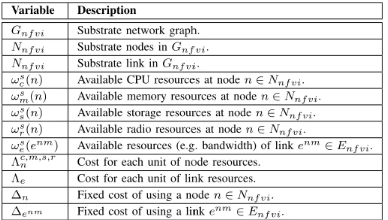
TABLE I: Substrate network parameters
Variable Description
Gnf vi Substrate network graph.
Nnf vi Substrate nodes inGnf vi.
Nnf vi Substrate link inGnf vi.
ωs
c(n) Available CPU resources at noden∈Nnf vi.
ωms(n) Available memory resources at noden∈Nnf vi.
ωs
s(n) Available storage resources at noden∈Nnf vi.
ωs
r(n) Available radio resources at noden∈Nnf vi.
ωs
e(enm) Available resources (e.g. bandwidth) of linkenm∈Enf vi.
Λc,m,s,rn Cost for each unit of node resources.
Λe Cost for each unit of link resources.
∆n Fixed cost of using a noden∈Nnf vi.
∆enm Fixed cost of using a linkenm∈Enf vi.
physical nodes that compose the substrate network andEnf vi
is the set of edges or links. An edgeenm∈E
nf viif and only
if a point–to–point connection exists between n∈Nnf vi and
m ∈ Nnf vi. With respect to the physical network, links are
actual wiring media, e.g., an Ethernet cable interconnecting the two nodes1. Four weights,ωsc(n), ωms(n), ωss(n), ωrs(n),
are assigned to each noden ∈Nnf vi : ωc,m,ss (n)∈ N+ and
ωrs(n) ∈ R+,0 ≤ ωrs(n) ≤ 1 representing the packet and
radio processing resourcesavailableon that node. Nodes with all weights equal to 0 (zero) are assumed to be pure packet forwarding nodes. Nodes with ωs
c > 0, ωms > 0, ωss > 0,
andωs
r= 0 are assumed to be pure packet processing nodes.
Finally, nodes with ωsc = ωsm = ωss = 0 and ωsr > 0 are
assumed to be pure radio access nodes. Another weight ωs
e(enm) assigned to each link enm ∈
Enf vi : ωes(e nm) ∈
N+ represents the capacity of the
link connecting two nodes. In order to avoid exceeding the nominal capacity of the substrate links, traffic shaping is implemented at the nodes with packet and/or radio processing capabilities. Finally, letPnf vibe the set of all substrate paths
andPnf vi(s, t)the shortest path between nodess, t∈Nnf vi.
Table I summarizes the NFVI parameters. The weightsωs
c,m,s(n)associated with the packet
process-ing nodes represent, respectively, the amount of CPU, memory, and storage resources available on that node, while the weights ωs
r(n) are specific to the radio access nodes and represent
the normalized amount of wireless resources available at that node. Notice, how with radio access nodes we refer to the generic nodes providing end–users terminals with wireless connectivity, e.g. Access Points (APs) in a 802.11 network or cellular eNodeBs (eNBs) in an LTE network.
For the sake of simplicity and without any loss of generality in this work we assume that all radio–enabled nodes initially have the same amount of resources ωs
r(n) = 1,∀n∈Nnf vi.
Notice how in this model we make no assumption on the type of radio resources that can be available at a certain node. In a 802.11–based network ωrs(n) could model the amount of airtime available for transmission in the downlink direction. Similarly, in an OFDMA–based network (e.g. LTE), ωs
r(n)
could be used to model the available radio resources in time
Forwarding + Processing Forwarding Forwarding + Radio Access 50,50,50 50,50,50
Fig. 1: NFVI network model. The figure shows the three basic virtual resources: forwarding, packet processing, and radio access.
and frequency on both the uplink and downlink directions. A sample substrate network is sketched in Fig. 1. The network is composed by 10nodes interconnected together. In order to improve readability link weights have been omitted. The substrate network in this example consists of 6 radio access nodes (at the bottom of the picture), and4switches, 2
of which supporting just basic forwarding capabilities.
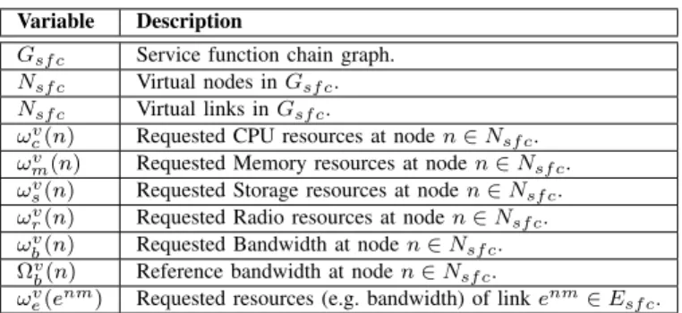
B. Service Function Chain Requests
Users are allowed to request SFCs as adirectedandacyclic
graphs Gsf c = (Nsf c, Esf c). Where Nsf c denotes the set
of nodes (i.e. VNFs) and Esf c ⊆ Nsf c×Nsf c denotes the
set of virtual links. An edge enm ∈ E
sf c if and only if
the packets from VNF n ∈ Nsf c must be forwarded to the
VNF m ∈ Nsf v Notice that as opposed to the previous
NFVI model, nodes in SFC requests represent virtual network functions through which packets must undergo before leaving the network. Packet processing nodes and links in the SFC request shares the same weights as for the NFVI substrate network (ωv
c, ωmv, ωsv, ωve). On the other hand, provisioning
of radio resources can be made either in terms of fraction of available radio resources (ωv
r) or in terms of bandwidth
(ωv
b). In the former case the users will specify the percentage
of radio resources they want assigned to a certain node, while in the latter case the users will specify the amount of bandwidth assigned to the node. A single SFC request can mix bandwidth–based and resource–based provisioning models.
Due to their stochastic nature, available bandwidth is a time–varying quantity in wireless networks. Channel fading, but also to the distribution of end–users, can greatly influence the network performance. For example, users at the center of the cell will be, in general, able to use more efficient modu-lations and coding schemes thus achieving higher throughput for a fixed amount of radio resources than users at the edges of the cell. As a result, when the bandwidth–based provisioning model is employed, also the actual channel conditions experi-enced by the end–users must be taken into account.
Let us callb(n)the actual aggregate throughput of the vir-tual radio noden∈Nsf cin the fraction of resources currently
assigned the the node. We can then introduce an additional parameter named reference throughput Ωvb(n)≥ωbv(n)upon which the bandwidth reservation ωv
b(n) is enforced. If we
name ω˜v
b(n) the effective target bandwidth for virtual radio
TABLE II: Service function chain request parameters
Variable Description
Gsf c Service function chain graph.
Nsf c Virtual nodes inGsf c.
Nsf c Virtual links inGsf c.
ωv
c(n) Requested CPU resources at noden∈Nsf c.
ωv
m(n) Requested Memory resources at noden∈Nsf c.
ωv
s(n) Requested Storage resources at noden∈Nsf c.
ωv
r(n) Requested Radio resources at noden∈Nsf c.
ωv
b(n) Requested Bandwidth at noden∈Nsf c.
Ωvb(n) Reference bandwidth at noden∈Nsf c.
ωev(enm) Requested resources (e.g. bandwidth) of linkenm∈Esf c.
noden, then we have:
˜ ωvb(n) = ( ωv b(n) ifb(n)≥Ω v b(n) ωvb(n)Ωbv(n) b(n) ifb(n)<Ωvb(n) (1)
The parameter Ωvb(n) represents a threshold above which the bandwidth reservation is respected. Otherwise ωv
b(n) is
linearly scaled down. Choosing a small value forΩvb(n)means that the network can utilize more resource in order to satisfy the bandwidth requirement, which in time could result in an higher pricing. Conversely, a high value forΩv
b(n)means that
the network will try to satisfy the bandwidth requirements only for the users that are experiencing good channel conditions.
If we define ωvr(n) =
˜
ωv b(n)
b(n) , then, in order for the SFC
request to be feasible, it must hold:
X n∈Nb sf c ˜ ωv b(n) b(n) + X n∈Nr sf c ωrv(n)≤ωrv(m) = 1 (2)
Which means that the sum of the fractions of radio resources allocated to virtual nodes must be less than or equal to the resources available at the substrate node m. Table II summarizes the SFC request parameters. A practical example for both the resource allocation model and the performance isolation mechanism can be found in Sec. VII-B.
A few sample SFC requests are sketched in Fig. 2. Notice that wireless terminals are not represented in that they are outside the control of the orchestration framework. The SFC request in Fig. 2b consists of three VNFs including a WiFi hotspot, a firewall, and a load balancer. The WiFi hotspot request will also include parameters such as the name of the network and the authentication parameters (e.g. type of encryption, RADIUS server to be used, etc.) however these kind of information are purely functional and are thus omitted in this section. The SFC request in Fig. 2a and 2c represents respectively a performance enhancing VNF and a wireless channel monitoring VNF. Notice how the SFC request in Fig. 2b is using bandwidth–based provisioning while the SFC request in Fig. 2a is using resource–based provisioning. Finally, being a pure passive SLA monitoring SFC, the request in Fig. 2c requires zero resources on the radio nodes.
C. Virtual Network Function Placement
In this section we shall provide the optimal ILP formulation for the SFC embedding problem, then in the next section we
Duplicate Filter WAN WiFi Hotspot WiFi Hotspot 6, 10 6, 10 50,0,0
(a) Uplink/Downlink decoupling. Bandwidth–based provisioning model is employed in this request.
Load Balancer
WAN
WAN WiFi Hotspot Firewall
6, 10 50,0,0 50,0,0
(b) Radio access network sharing. Bandwidth–based provisioning model is employed in this request.
TX Statistics Packet Sniffer
TX Statistics
Packet Sniffer Frame Counter 0 0 50,10,25 WAN 50,0,0 50,0,0
(c) SLA monitoring. Radio resources–based provisioning model is employed in this request.
Fig. 2: Sample Service Function Chains Requests.
will present an approximation algorithm. The overall objective is to periodically compute a new placement based on the estimation of the available radio resources while minimizing the cost of mapping virtual functions to substrate nodes. The chosen objective function is the following:
min X n∈Nnf vi h ∆nΨn+ X n0∈N sf c wvc(n0)Λcn+wvm(n0)Λmn+ wsv(n0)Λsn+wrv(n0)ΛrnΦnn0i+ X e∈Enf vi X e0∈E sf c ωve(e0)ΛeΦe 0 e
whereΨn∈0,1is a binary variable indicating if the physical
noden∈Nnf viis used in the mapping. Similarly,Φn
0
n ,Φe
0
e ∈
0,1are two binary variables indicating respectively if the VNF n0 ∈ Nsf v has been mapped to node n ∈ Nnf vi and if the
virtual link e0 ∈E
sf c has been mapped to the substrate link
e∈Enf vi.
A valid solution is the one where the resources utilized by the SFC request are at most equal to the available resources on the substrate network nodes:
X n0∈N sf c ωcv(n0)Φ n0 n ≤ω s c(n) ∀n∈Nnf vi (3) X n0∈N sf c ωmv(n0)Φnn0 ≤ωms(n) ∀n∈Nnf vi (4) X n0∈N sf c ωsv(n0)Φnn0 ≤ωss(n) ∀n∈Nnf vi (5) X n0∈N sf c ωvr(n0)Φn 0 n ≤ωrs(n) ∀n∈Nnf vi (6) and links: X e0∈E sf c ωve(e0)Φe 0 e ≤ωse(e) ∀e∈Enf vi (7)
Every VNF in the SFC request is mapped to a different substrate node:
X
n0∈N
sf c
Φnn0 ≤1 ∀n∈Nnf vi (8)
Every VNF in the SFC request is mapped only once:
X
n∈Nnf vi
Φnn0 = 1 ∀n0∈Nsf c (9)
In terms of radio resources requirements, the following con-strain, deriving from (1) and (2), enforces that for every radio processing noden∈Nnf via feasible request has been made:
X n0∈Nb sf c ωv b(n0) Ωv b(n0) Φnn0+ X n0∈Nr sf c ωrv(n0)Φnn0 ≤1 ∀n∈Nnf vi (10) Finally, the following constraint enforces that for each link enm∈Esf cthere must be a continuous path allocated between
the pair of physical nodes on top of which the VNFs n, m∈
Nsf c have been mapped. j>i X j∈Nnf vi Φeenmij − j<i X j∈Nnf vi Φeenmji = Φni −Φmi (11) ∀i∈Nnf vi ∀enm∈Esf c IV. HEURISTIC
The ILP formulation described in the previous section cannot be applied to realistic scenarios due to its limited scalability. For example, embedding an SFC request composed of 6 VNFs arranged in linear topology over a k = 4 fat– tree can take up tp 30 seconds of time on Intel Core i7 laptop (2.2 GHz CPU, 8Gb RAM) using the Matlab ILP solver (intlinprog). In this section we present an effective heuristic that can handle more complex requests in almost real–time.
The proposed heuristic is composed of three steps. In the first step for each virtual node n ∈ Nsf c, the heuristic
computes the list of candidate substrate nodes (see Alg. 1). In the second step, the virtual nodes n ∈ Nsf c are sorted
according to the number of candidate substrate nodes (see Alg. 2). The list is sorted in decreasing order, i.e. virtual nodes with the smallest number of candidate nodes are put on top.
We define the virtual edge mapping costW :Esf c×Nnf vi×
Nnf vi→Rbetween a virtual edgeenm∈Esf cand a pair of
substrate nodesp, q∈Nnf vi as follows:
W(enm, p, q) =∆p+ωc,m,s,rs (p)ω v c,m,s,r(n)+ ∆q+ωc,m,s,rs (q)ω v c,m,s,r(m)+ X e∈Pnf vi(p,q) ωes(e)ωve(enm)
Algorithm 1 Compute list of candidate substrate nodes 1: procedureFindCandidates(Nnf vi,Nsf c) 2: forn∈Nsf cdo 3: forp∈Nnf vido 4: ifωsc,m,s,r(p)>=ω v c,m,s,r(n)then 5: n.candidates.add(p) 6: end if 7: end for 8: end for 9: end procedure
Algorithm 2 Sort list of candidate substrate nodes
1: procedureSortCandidates(Nsf c)
2: sort(Nsf c)
3: end procedure
Algorithm 3 Nodes and links assignment
1: procedureNodeAndLinkAssignment(Gnf vi,Gsf c) 2: forn∈Nsf cdo 3: forp∈vi.candidatesdo 4: ifp.usedthen 5: continue 6: end if 7: form∈vi.neighborsdo 8: cost= +∞ 9: ifm.mappedthen 10: cost=W(enm, p, m.mapped) 11: else 12: forq∈m.candidatesdo 13: cost=min(cost, W(enm, p, q)) 14: end for 15: end if
16: mapping cost(p)+ =cost
17: end for 18: end for 19: p←argmin(mapping cost(p)) 20: n.mapped←p 21: p.used←T rue 22: form∈n.neighborsdo 23: ifm.mappedthen
24: Allocate pathPnf vi(n.mapped, m.mapped)
25: end if
26: end for
27: end for
28: end procedure
In the third step, for each virtual node n ∈ Nsf c and for
each candidate substrate nodem∈n.candidatesthe heuristic considers all the neighboring nodes m ∈ n.neighbors. The heuristic then computes how much it would cost to embed each virtual node pairs n, mincluding the cost to embed the virtual edge enm∈Esf c. The heuristic then assigns the node
n to the substrate node m ∈ n.candidates with the lowest virtual edge mapping cost (see Alg. 3).
V. EVALUATION
The goal of this section is to compare the relative perfor-mance of the ILP–based placement algorithm with the per-formance of our placement heuristic using different synthetic substrate network and different SFC requests. In this section we shall first describe the simulation environment and then the
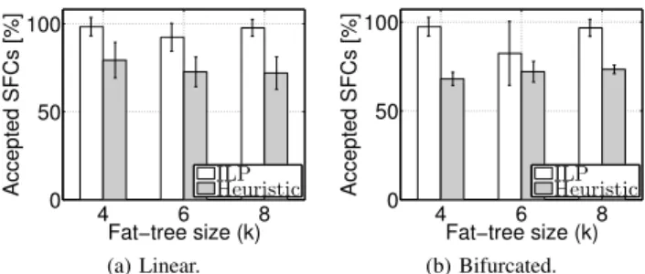
4 6 8 0 50 100 Accepted SFCs [%] Fat−tree size (k) ILP Heuristic (a) Linear. 4 6 8 0 50 100 Accepted SFCs [%] Fat−tree size (k) ILP Heuristic (b) Bifurcated.
Fig. 3: Number of successful embedding using the ILP–based algo-rithm and the heuristic with different virtual and substrate topologies.
performance metrics. Simulations are carried out in a discrete event simulator implemented in MatlabR.
A. Simulation Environment
The ILP–based placement algorithm and the proposed placement heuristic are evaluated in two different scenarios. In the first scenario, linear VNF requests, similar to the ones depicted in Fig. 2b, are considered. Conversely, in the second scenario, bifurcated VNF requests, similar to the ones depicted in Fig. 2a, are considered. The number of VNFs in each SFC request as well as the actual amount of radio, computational, memory, storage, and link resources are randomly generated for each request.
In this study we assume that SFC requests are embedded sequentially until the substrate network resources are ex-hausted. The reference substrate network isk–ary fat–tree with k = 4,6,8, where leaf nodes are WiFi Access Points (APs) rather than hosts. This results in a total of, respectively, 16,
54, and128 WiFi APs. The computational, memory, storage, radio, and link resources for the substrate network are initially set to, respectively, 100, 100,100,1,100. The fixed cost of using a node∆n is set to10while the cost of using each unit
of nodeΛc,m,s,r
n and link Λe resources is set to1.
The number of VNFs in each SFC request is uniformly distributed between [3,6]. The computational, memory, stor-age, radio, and link requirements for each SFC requests are uniformly distributed between, respectively,[1,5],[1,5],[1,5],
[0.1,0.5], and[1,5].
The metrics used in this study are standard ones adopted in several other related works (see, e.g., [8], [27], [28]). For each scenario the number of accepted requests, the average embedding cost, and the execution time using either the ILP– based placement or the proposed heuristic are considered. Reported results are the average of10simulations.
B. Simulation Results
Figure 3 and Fig. 4 shows the percentage of accepted SFC requests for different substrate networks and the average em-bedding cost. As expected the ILP–based placement algorithm is more efficient than the proposed heuristic in mapping the incoming requests. This can be seen in terms of both a higher number of successful embedding as well as a lower average embedding cost.
On the other hand, Fig. 5 shows that the average amount of time required to embed a single SFC request using the
4 6 8 0 10 20 30 40 Embedding Cost Fat−tree size (k) ILP Heuristic (a) Linear. 4 6 8 0 20 40 60 Embedding Cost Fat−tree size (k) ILP Heuristic (b) Bifurcated.
Fig. 4: Average embedding cost using the ILP–based algorithm and the heuristic with different virtual and substrate topologies.
4 6 8 0 20 40 Execution Time [s] Fat−tree size (k) ILP Heuristic (a) Linear. 4 6 8 0 20 40 60 80 Execution Time [s] Fat−tree size (k) ILP Heuristic (b) Bifurcated.
Fig. 5: Average execution time using the ILP–based algorithm and the heuristic with different virtual and substrate topologies.
ILP–based placement algorithm is significantly higher than the time required to embed the same request using our heuristic. The ILP problem becomes essentially intractable for substrate networks with more than a few tens of nodes (irrespective of the the number of VNFs in the request), while using our heuristic we can effectively embed complex SFC requests on substrate networks with hundreds of nodes in a limited amount of time. For example embedding a linear SFC request composed of 10 VNFs over a k = 24 fat–tree network (214
nodes) takes less than 30seconds using our heuristic. VI. IMPLEMENTATION
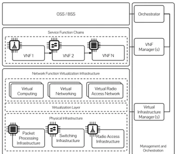
We implemented the VNF placement heuristic presented in this work in a proof–of–concept NFV management and orchestration framework. Notice that the prototype currently targets only wireless access networks based on the 802.11 family of standards and as a consequence the applications described in the next section targets mainly typical Enterprise WLAN and Campus network scenarios. Nevertheless, as seen in the previous section the provisioning model does not make any assumption about the particular link–layer technology and can be as well applied to any kind of radio access network including OFDMA networks such as LTE and LTE–Advanced. The prototype architecture is loosely modeled after the ETSI reference NFV Architecture [5]. As it can be seen in Fig. 6, the architecture is conceptually divided into three layers. The bottom layer represents the NFVI which includes both the physical resources as well as the virtualized resources exposed by a virtualization layer. In the second layer we have the actual VNFs which are the software implementation of a particular network function which is capable of being executed over the NFVI. Finally, in the third layer we have the
Service Function Chains
Management and Orchestration Network Function Virtualization Infrastructure
Physical Infrastructure
Packet Processing Infrastructure
Switching
Infrastructure Radio Access Infrastructure Virtualization Layer
Computing
InfrastructureComputing Virtual InfrastructureComputingNetworking Virtual Access Network InfrastructureComputingVirtual Radio
VNF 1 VNF 2 VNF N Virtual Infrastructure Manager (s) VNF Manager (s) Orchestrator OSS / BSS
Fig. 6: Reference network function virtualization architecture [5].
Operational Support System (OSS) and the Business Support System (BSS) used by the network administrators to operate and manage their virtual networks. The Management and Or-chestration plane covers the orOr-chestration and the management of physical and/or virtual resources that support the NFVI as well as the life–cycle management of the VNFs, i.e. creation, configuration, monitoring, and destruction.
Our architecture currently accounts for three kinds of NFVI resources, namely: basic forwarding nodes (i.e. OpenFlow switches), packet processing nodes, and radio access nodes. The latter, in addition to the features supported by the packet processing node, also embed specialized hardware in the form of one or more 802.11 Wireless NICs.
A. Management plane
As Virtual Infrastructure Managers (VIMs) we use a com-bination of frameworks. Ryu [29] is used to configure the switching fabric. The SD–RAN controller presented by the authors in [30] is used in the wireless access. A dedicated controller, named Programmable Network Fabric Controller, is used to manage the packet processing nodes. All three VIMs expose a RESTful interface implementing basic CRUD (Create, Read, Update, Delete) operations.
B. Orchestrator
From an architectural standpoint, the VNF placement al-gorithm resides in the Orchestrator which is in charge of deciding whether a particular request can be accepted or if it must be refused. If a request is accepted, then theOrchestrator
is in charge of mapping the request onto the substrate network, i.e., network resources must be allocated and configured on both the substrate nodes and the substrate links and the VNFs must be instantiated on the selected nodes.
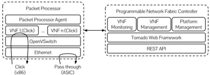
C. Programmable Network Fabric
We name Programmable Network Fabric the set of all packet processing nodes in the NFVI. As it can be seen in
Packet Processor
Pass through (ASIC) Click
(x86)
Programmable Network Fabric Controller
REST API VNF
Monitoring
Tornado Web Framework VNF
Management ManagementPlatform VNF n (Click)
OpenVSwitch Ethernet VNF 1 (Click)
Packet Processor Agent ...
Fig. 7:Programmable Network Fabric Controller.
Fig. 7 each packet processing node includes an OpenVSwitch instance, one or more VNFs, and one Packet Processor Agent. The latter is in charge of monitoring the status of each VNF as well as handling CRUD requests coming from the
Programmable Network Fabric Controller. In the current
implementation the monitoring features includes: number of packets/bytes transmitted and received as well as the amount of resources utilized (cpu time, memory, storage) by each VNF. Notice how wireless access is also a VNF.
In our prototype we use Click [31] as a single solution for advanced packet processing. Click allows to build complex VNFs using simple and reusable components, calledelements. Click includes over300elements supporting functions such as packet classification, access control, deep packet inspection. Elements can be composed in order to realize complex VNFs. Finally, Click is easily extensible with custom processing elements making it possible to support features that are not provided by the standard elements.
The Programmable Network Fabric Controller is build on
top of the Tornado Web Framework. Communications between packet processors and the Programmable Network Fabric
Controllers take place over a persistent TCP connection. The
Programmable Network Fabric Controller can run multiple
SFC requests on top of the same physical infrastructure. An SFC request consists of multiple VNFs deployed at one or more packet processors. Each VNF is defined by a number of attributes including: amount of allocated resources, the Click configuration, the OpenVSwitch port(s) to which the VNF should be connected, and the physical packet processor on top of which the VNF shall be deployed.
Finally, we implemented the packet processing nodes on top of general purpose and off–the–shelf components. In particular the packet processing capabilities are provided by embedded nodes based on the Soekris net6501–70 platform. Such platform consists of a standard Intel Atom CPU (x86 architecture, single core 1.6 GHz,2 Gb RAM) equipped with
12 Ethernet ports and running a standard Linux OS (Ubuntu 15.04 in our case).
VII. APPLICATIONS
In this section we shall describe three SFCs implemented and tested over a small scale testbed deployed at CREATE– NET premises. The testbed, depicted in Fig. 1, consists of two OpenFlow–switches, two packet processing nodes, and
20 programmable WiFi APs.
A. Uplink/Downlink Decoupling
Wireless, and in particular mobile networks, have been so far designed around the requirements of the downlink (i.e. cell or access point selection is performed using downlink signal strength measurements). In the recent years, however, we have witnessed a mushrooming of new uplink–centric applications such as Machine Type Communications (MTC), Internet of Things (IoT), and Vehicle to Infrastructure (V2I) as well as of symmetric mobile applications. This calls for a paradigm shift where the traffic originated from a wireless client is received by one node while the traffic destined to the same client is transmitted by another node. This kind of network setup is usually referred to as uplink/downlink decoupling and, in its most general form, can consists of two possibly non overlapping sets of transmitting and receiving nodes.
The previously introducedEmPOWERplatform [30] allows for mobility management policies whereby a wireless client downlink can be scheduled on one WiFi AP while the uplink can be scheduled on one or more WiFi APs. This feature allows to exploit the broadcast nature of the wireless medium and to opportunistically receive the same transmission at multiple in–range APs. However, if not properly controlled such a feature can lead to an overload in the network core. For example, a wireless client scheduled on N APs in the uplink direction could increase the load on the network core by a factor ofN. Moreover, a straightforward implementation of such a mechanism could generate a significant increase in the number of duplicate packets which in time could trigger at the transport layer.
In order to address this issue we implemented a VNF which filters out duplicate 802.11 frames based on their sequence number. Traffic originated from clients is received at one or more APs where it is encapsulated (802.11 over Ethernet) and then forwarded to a packet processing node where the frame filtering VNF is deployed. This VNF is also responsible for decapsulating the 802.11 frame and LLC header and encapsulation in an Ethernet header before forwarding it to its intended destination. The Click script implementing the duplicate filtering VNF is reported in the listing below2.
FromHost ( v n f 0 ) −> i n : : C o u n t e r ( ) −> S t r i p ( 1 4 ) −> d u p e : : W i f i D u p e F i l t e r ( ) −> W i f i D e c a p ( ) −> o u t : : C o u n t e r ( ) −> ToHost ( v n f 0 ) ;
Listing 1: Duplicate filtering VNF.
In order to evaluate this VNF we exploited a network setup composed of a single client and three APs. Traffic is injected from the wireless client as a single UDP stream. Packet transmission rate and payload are kept fixed at, respectively,
100packets/s and1472bytes. Impairments on the link between client and APs are simulated by randomly dropping received frames with probability p at all receiving APs. For all mea-surements a total of6000frames were generated. Confidence
2vnf0is a virtual interface attached to the OpenVSwitch instance running
1 2 3 0 50 100 Delivery Ratio [%] Number of uplinks PL=0.05 PL=0.2 PL=0.8
(a) Packet Loss.
1 2 3 0 1 2 3 Bandwidth [Mbps] Number of uplinks PL=0.05 PL=0.2 PL=0.8 (b) BW w/o VNF. 1 2 3 0 0.5 1 Bandwidth [Mbps] Number of uplinks PL=0.05 PL=0.2 PL=0.8 (c) BW w/ VNF.
Fig. 8: Packet loss (a) and network utilization (b and c) for a single client scheduled on multiple APs on the uplink direction.
intervals were very small for all the data points and have therefore be omitted in order to improve readability. Measure-ments have been taken using three packet dropping probability, namely:0.05(good channel conditions),0.2(medium channel conditions), and0.8 (poor channel conditions)
As it can be seen from Fig. 8a, the end–to–end packet delivery ratio increases with the number of available uplinks. The proposed uplink/downlink decoupling solution can pro-vide a small performance improvement even when the channel conditions are good (P L = 0.05). On the other hand the performance improvements are significant when the channel condition get worse. In particular this solution allows to turn an essentially broken channel (4out of5dropped packet) into an usable channel (1out of2dropped packets). Finally, in Fig. 8b and Fig. 8c we can see the impact of the duplicate filtering VNF on the bandwidth utilization. As expected without the VNF the bandwidth utilization increases with the number of uplink, while using the VNF filtering the bandwidth utilization does not exceed the nominal goodput.
B. Radio Access Network Sharing
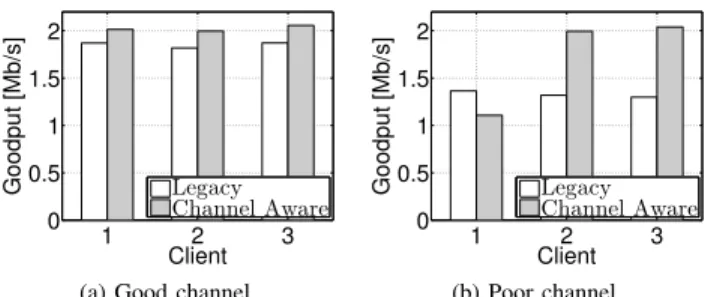
In this use case we aim at demonstrating the traffic isolation features enabled by our resource provisioning model. We consider two tenants each requesting an SFC similar to the one depicted in Fig. 2b. The bandwidth request coming from Tenant 1 and 2 is, respectively 4 and 2 Mb/s, while the reference bandwidth (Ωvb) was set to 6Mb/s for both tenants. The network setup used for the measurements consists of 3 clients. Clients 1 and 2 are using the Tenant’s 1 network, while Client 3 is in using Tenant’s 2 network. Traffic is generated from a server sharing the same backhaul with the AP and consists of three UDP stream (one for each client). Each stream has constant inter–departure time and packet size resulting in a transmission rate of 10 Mb/s for each stream. In order to simulate an hotspot with limited capacity the rate control algorithm used by the access point has been modified in order to always use the lowest transmission rate (6 Mb/s). Measurements have been carried in two different scenarios differentiated by the channel condition experienced by client number 1 which is positioned in such a way to experience channel condition raging from GoodtoPoor.
As it can be seen from Fig. 9a, when Client 1 is experiencing good channel conditions the proposed resource provisioning method is able to satisfy the bandwidth request for both tenants (notice that Tenant 1 request of 4 Mb/s has been equality partitioned among the two clients). On the other hand, when Client 1 starts experiencing poor channel conditions (see
1 2 3 0 0.5 1 1.5 2 Goodput [Mb/s] Client Legacy Channel Aware
(a) Good channel.
1 2 3 0 0.5 1 1.5 2 Goodput [Mb/s] Client Legacy Channel Aware (b) Poor channel.
Fig. 9: Isolation across clients in different networks. Client1and 2
are in Tenant1’s network, while Client3is in Tenant2’s network.
Fig. 9b) the legacy resource provisioning mechanism allocates the same bandwidth to all the clients. This behavior, known as IEEE 802.11 performance anomaly [32], allows a node which experiences poor channel conditions to monopolize the wire-less medium lowering the performance of the whole system. Conversely, the proposed resource provisioning mechanism can meet the bandwidth reservations made by the two tenants by linearly scaling down the amount of resources allocated to the tenant that is experiencing poor channel conditions.
C. Service Level Agreement Monitoring
In this use case we aim at demonstrating basic SLA moni-toring capabilities. The SFC is depicted in Fig. 2c. A Packet
Sniffer VNF is deployed on radio nodes. Notice that, since
the packet sniffing VNF is not allowed to transmit traffic, the radio resource requirements for this VNF are set to zero. The
Packet Sniffercollects all transmissions within decoding range
of the radio node and forwards them to a singleTX Statistics
VNF which tracks the meta–data associated to transmissions, in particular the following information are monitored:RSSI(in
dB),Transmission Rate(in Mb/s),Length(in bytes),Duration
(in µsec), and the number of retransmissions. The collected frames are then forwarded to a commonFrame Counter VNF which computes aggregate statistics. This VNF could serve as a basis for a QoE management solution.
VIII. CONCLUSIONS
Network function virtualization is rapidly emerging as a flexible solution to deploy and operate network services. However, in order to fully exploit the benefits of this paradigm, the concept of virtual network function must be extended to include also the radio access network, providing MVNOs with the highest level of flexibility in the definition of virtual radio access functions while at the same time allowing for an efficient use of the substrate network. In this paper we tackled this challenge by presenting a novel formulation of the VNF placement problem which encompass also the radio access network. We present then a ILP–based optimal solution for small networks and a scalable heuristic for larger de-ployments. We also report on a preliminary proof–of–concept implementation of a NFV Management and Orchestration framework for Enterprise WLANs and on a few VNFs. As future work we plan to investigate resiliency properties of such NFV architecture, VNF migration, and joint RAN resource allocation and VNF orchestration strategies.
REFERENCES
[1] R. Riggio, T. Rasheed, and R. Narayanan, “Virtual Network Functions Orchestration in Enterprise WLANs,” inProc. of IEEE ManFI, Ottawa, ON, Canada, 2015.
[2] M. Dobrescu, N. Egi, K. Argyraki, B.-G. Chun, K. Fall, G. Iannaccone, A. Knies, M. Manesh, and S. Ratnasamy, “Routebricks: Exploiting parallelism to scale software routers,” inProc. of ACM SOSP, 2009. [3] S. Han, K. Jang, K. Park, and S. Moon, “Packetshader: A
gpu-accelerated software router,” SIGCOMM Comput. Commun. Rev., vol. 40, no. 4, pp. 195–206, Aug. 2010.
[4] K. K. Ram, A. L. Cox, M. Chadha, and S. Rixner, “Hyper-switch: A scalable software virtual switching architecture,” inProc. of USENIX ATC, 2013.
[5] E. T. S. I. (ETSI),ETSI GS NFV 002 Network Functions Virtualisation (NFV); Architectural Framework, December 2014.
[6] “OPNFV: Open Platform for Network Function Virtualization.” [Online]. Available: https://www.opnfv.org/
[7] “OpenMANO.” [Online]. Available:
https://github.com/nfvlabs/openmano
[8] M. Chowdhury, M. R. Rahman, and R. Boutaba, “ViNEYard: Virtual network embedding algorithms with coordinated node and link map-ping,”Networking, IEEE/ACM Transactions on, vol. 20, no. 1, pp. 206 –219, February 2012.
[9] M. Chowdhury, F. Samuel, and R. Boutaba, “Polyvine: policy-based virtual network embedding across multiple domains,” inProc. of ACM VISA, 2010.
[10] A. Fischer, J. Botero, M. Till Beck, H. de Meer, and X. Hesselbach, “Virtual network embedding: A survey,”Communications Surveys Tuto-rials, IEEE, vol. 15, no. 4, pp. 1888–1906, Fourth 2013.
[11] D. Breitgand, A. Epstein, A. Glikson, A. Israel, and D. Raz, “Network aware virtual machine and image placement in a cloud,” in Proc. of IEEE CNSM, 2013.
[12] M. Barshan, H. Moens, and F. De Turck, “Design and evaluation of a scalable hierarchical application component placement algorithm for cloud resource allocation,” inProc. of IEEE CNSM, 2014.
[13] M. Barshan, H. Moens, S. Latre, and F. De Turck, “Algorithms for efficient data management of component-based applications in cloud environments,” inProc. of IEEE NOMS, 2014.
[14] B. Jennings and R. Stadler, “Resource management in clouds: Survey and research challenges,”Journal of Network and Systems Management, pp. 1–53, 2014.
[15] R. Guerzoni, R. Trivisonno, I. Vaishnavi, Z. Despotovic, A. Hecker, S. Beker, and D. Soldani, “A novel approach to virtual networks embedding for sdn management and orchestration,” inProc. of IEEE NOMS, 2014.
[16] S. Clayman, E. Maini, A. Galis, A. Manzalini, and N. Mazzocca, “The dynamic placement of virtual network functions,” in Proc. of IEEE NOMS, 2014.
[17] H. Moens and F. De Turck, “VNF-P: A model for efficient placement of virtualized network functions,” inProc. of IEEE CNSM, 2014. [18] L. Xia, S. Kumar, X. Yang, P. Gopalakrishnan, Y. Liu, S. Schoenberg,
and X. Guo, “Virtual wifi: Bring virtualization from wired to wireless,” SIGPLAN Not., vol. 46, no. 7, pp. 181–192, Mar. 2011. [Online]. Available: http://doi.acm.org/10.1145/2007477.1952706
[19] P. Lv, X. Wang, and M. Xu, “Virtual access network embedding in wireless mesh networks,” Ad Hoc Netw., vol. 10, no. 7, pp. 1362–1378, Sep. 2012. [Online]. Available: http://dx.doi.org/10.1016/j.adhoc.2012.03.016
[20] P. Lv, Z. Cai, J. Xu, and M. Xu, “Multicast service-oriented virtual net-work embedding in wireless mesh netnet-works,”Communications Letters, IEEE, vol. 16, no. 3, pp. 375–377, March 2012.
[21] G. Bhanage, R. Daya, I. Seskar, and D. Raychaudhuri, “Vnts: A virtual network traffic shaper for air time fairness in 802.16e systems,” in Communications (ICC), 2010 IEEE International Conference on, May 2010, pp. 1–6.
[22] G. Bhanage, D. Vete, I. Seskar, and D. Raychaudhuri, “Splitap: Lever-aging wireless network virtualization for flexible sharing of wlans,” in Global Telecommunications Conference (GLOBECOM 2010), 2010 IEEE, Dec 2010, pp. 1–6.
[23] R. Kokku, R. Mahindra, H. Zhang, and S. Rangarajan, “Nvs: A substrate for virtualizing wireless resources in cellular networks,” Networking, IEEE/ACM Transactions on, vol. 20, no. 5, pp. 1333–1346, Oct 2012. [24] ——, “Cellslice: Cellular wireless resource slicing for active ran
shar-ing,” inProc. of IEEE COMSNETS, 2013.
[25] G. Bhanage, I. Seskar, R. Mahindra, and D. Raychaudhuri, “Virtual basestation: Architecture for an open shared wimax framework,” inProc. of ACM VISA, 2010.
[26] G. Smith, A. Chaturvedi, A. Mishra, and S. Banerjee, “Wireless vir-tualization on commodity 802.11 hardware,” inProc. ACM WinTECH, 2007.
[27] Y. Minlan, Y. Yi, J. Rexford, and M. Chiang, “Rethinking virtual network embedding: substrate support for path splitting and migration,” SIGCOMM Comput. Commun. Rev., vol. 38, no. 2, pp. 17–29, Mar. 2008.
[28] Y. Zhu. and M. Ammar, “Algorithms for Assigning Substrate Network Resources to Virtual Network Components,” inProc. of IEEE INFO-COM, Barcelona, Spain, April 23-29 2006.
[29] “Ryu SDN Framework.” [Online]. Available: http://osrg.github.io/ryu/ [30] R. Riggio, M. Marina, J. Schulz-Zander, S. Kuklinski, and T. Rasheed,
“Programming abstractions for software-defined wireless networks,” Network and Service Management, IEEE Transactions on, vol. 12, no. 2, pp. 146–162, June 2015.
[31] E. Kohler, R. Morris, B. Chen, J. Jannotti, and M. F. Kaashoek, “The click modular router,” ACM Trans. Comput. Syst., vol. 18, no. 3, pp. 263–297, Aug. 2000.
[32] M. Heusse, F. Rousseau, G. Berger-Sabbatel, and A. Duda, “Per-formance anomaly of 802.11b,” in Proc. of IEEE INFOCOM, San Francisco, California, USA, 2003.