Supervisor
Environment: 90/25, 30, 30B, 40 Systems
L
This document contains the latest information available at the time of preparation. Therefore, it may contain descriptions of functions not implemented at manual distribution time. To ensure that you have the latest information regarding levels of implementation and functional availability, please consult the appropriate release documentation or contact your local Sperry Univac representative.
Sperry Univac reserves the right to modify or revise the content of this document. No contractual obligation by Sperry Univac regarding level, scope, or timing of functional . ) implementation is either expressed or implied in this document. It is further understood that in consideration of the receipt or purchase of this document, the recipient or purchaser agrees not to reproduce or copy it by any means whatsoever, nor to permit such action by others, for any purpose without prior written permission from Sperry Univac.
Sperry Univac is a division of the Sperry Corporation.
FASTRAND, SPERRY UNIVAC, UNISCOPE, UNISERVO, and UNIVAC are registered trademarks of the Sperry Corporation. ESCORT, PAGEWRITER, PIXIE, and UNIS are additional trademarks of the Sperry Corporation.
This document was prepared by Systems Publications using the SPERRY UNIVAC UTS 400 Text Editor. It was printed and distributed by the Customer Information Distribution Center (CIDC), 555 Henderson Rd., King of Prussia, Pa,, 19406.
PUBUcAflONs
UPDATE
Operating Systern/3 (0S13)
Supervisor
User Guide
This Library Memo announces the release and availability of Updating Package A to “SPERRY UNIVAC Operating System/3 (OS/3) Supervisor User Guide”, UP-8075 Rev. 3.
This update documents the following changes for release 8.0:
Enhancement of the OC STXIT routine
• Restrictions to the monitor routine
• Expansion of the Soft-Patch Symbiont debugging aid
• Enhancement of the job accounting facility
This update also includes minor technical corrections to material applicable to the supervisor prior to release 8.0.
Copies of Updating Package A are now available for requisitioning. Either the updating package only, or the complete manual with the updating package may be requisitioned by your local Sperry Univac representative. To receive only the updating package, order UP-8075 Rev. 3—A. To receive the complete manual, order UP-8075 Rev. 3.
Mailing Lists Mailing Lists ADO, AOl, 18, 18U, 19, l9U, 20, 2OU, Library Memo for
BZ, CZ and MZ 21, 21 U, 75, 75U, 76, and 76U UP-8075 Rev. 3—A
(Package A to UP-8075 Rev. 3, 75 pages plus Memo)
User Guide
UP4035 Rev, 3
This Library Memo announces the release and availability of “SPERRY UNIVAC® Operating System/3 (OS/3) Supervisor User Guide”, UP.8075 Rev. 3.
This revision of the OS/3 Supervisor User Guide completely replaces revision 2 and all its updates. For release 7.1 of 05/3, two new enhancements to the supervisor which this revision documents are:
Support of checkpoint files on SAT tapes; and
Workstation logging.
All other changes represent corrections to material that is applicable before release 7.1.
Destruction Notice: If you are going to OS/3 release 7,1, use this revision and destroy all previous copies. If you are not going to OS/3 release 7.1, retain the copy you are now using and store this revision for future use.
Copies of UP8075 Rev. 2, Updates A, B and C will be available for 6 months after the release of 7.1. Should you need additional copies of this edition, you should order them within 90 days of the release of 7.1. When ordering the previous edition of a manual, be sure to identify the exact revision and update packages desired.
Additional copies may be ordered by your local Sperry Univac representative.
Mailing Lists BZ, CZ and MZ
Mailing Lists 18, 18U, 19, 19U, 20, 20U, 21, 21U, 75, 75U, 76 and 76U
(Covers and 357 pages)
Library Memo for UP8075 Rev. 3 Operating System,...
Supervisor
8075 Rev. 3
UP-NUMBER SPERRY UNIVAC Operating System/3
A
UPDATE LEVEL PAGE PSS 1
PAGE STATUS SUMMARY
ISSUE: Update A — UP-8075 Rev. 3
RELEASE LEVEL: 8.0 Forward
11 1 Orig.
2 A 3,4 Orig. 5 A 6 Orig. 7,8 A 9 Orig. 10 A 11,12 Orig. Index 1 thru 10 Orig.
11 thru 13 A 14, 15 Orig. User Comment
Sheet
All the technical changes are denoted by an arrow(-0.-)in the margin. A down ward pointing arrow(
f
) next to a line indicates that technical changes begin at this line and continue until an upward pointing arrow (4)
is found. A horizontal arrow(-0.-)pointing to a line indicates a technical change in only that line. A horizontal arrow located between two consecutive lines indicates technical changes in both lines or deletions.Page Update
Part/Section Number Level
• Page Update . Page Update
Part/Section Number Level Part/Section Number Level
Cover/Disclaimer Orig. PART 4
Title Page Orig.
PSS 1 A
8 1 thru 6 Orig.
Preface 1, 2 Orig. 7 A
8 thru 48 Orig.
Contents 1 Orig. 49 A
2, 3 A 50 thru 63 Orig.
4thru6 Orig.
7, 8 A 9 1 thru 22 Orig.
9,10 Orig. 23 A
24 thru 26 Orig.
PART1 27 A
Title Page Orig. 28 Orig.
29 A
1 1 thru 3 Orig. 30 thru 34 Orig.
35 A
2 1 thru 8 Orig. 36 thru 42 Orig.
9 A 43 A
10,11 Orig. 44,45 Orig.
46,47 A
3 1 thru 10 Orig. 48 thru 57 Orig.
11 A 58,59 A
12 Orig. 60thru 63 A
PART 2
Title Page
10 Orig.
1 thru 23 Orig.
4 lthru3 A
4 Orig.
5 A
6 thru 14 Orig.
15 A
16 thru 18 Orig. l9thru22 A 23 thru 28 Orig.
29 A
30 thru 34 Orig. 35 thru 37 A
5 1 thru 18 Orig.
6 1 thru 7 Orig.
8 A
9 thru 24 Orig.
25 A
26 thru 55 Orig.
56,57 A
58 thru 63 Orig. PART 3
Title Page Orig.
7 1 thru 22 Orig,
8075 Rev, 3 UP-NUMBER
SPERRY UNIVAC Operating System/3
UPDATE LEVEL PAGE PSS 1
PAGE STATUS SUMMARY
. Page Update
Part/Section Number Level
Cover/Disclaimer
PSS 1
Preface 12 Contents I thru 10 PART 1
Title Page
1 lthru3
2 lthrull
3 lthrul2
PART 2
Title Page
4 lthru37
5 lthrul8
6 lthru63
PART 3
Title Page
7 lthru22
PART 4
Title Page
3 lthru63
J lthru59
10 1 thru 23
11 lthrul2
Index 1 thru 15 User Comment
heet
ISSUE: UP8O75 Rev, 3 RELEASE LEVEL: 7,1 Forward
Page-- Update
Page Update
Part/Section
Number Level
Part/Section Number Level
8075 Rev. 3 SPERRY UNIVAC Operating Systeml3 Preface 1
UP-NUMBER - UPDATE LEVEL PAGE
Preface
This manual is one of a series designed to instruct and guide the programmer in the use of the SPERRY UNIVAC Operating System/3 (OS/3). This manual specifically describes the OS/3 supervisor and its effective use. Its intended audience is the novice programmer with a basic knowledge of data processing, but with limited programming experience, and the programmer whose experience is limited to other than SPERRY UNIVAC systems.
Prerequisite to the use of this manual is a general knowledge of the OS/3 assembler, job control, and data management.
Two other manuals are available that cover the supervisor; one is an introductory manual and the other is a programmer reference manual (PRM). The introductory manual briefly describes the supervisor and its facilities. The PRM provides the characteristics of OS/3 supervisor in skeletal form and is intended as a quick-reference document for the programmer experienced in the use of the supervisor.
This user guide is subdivided into the following parts:
‘ PART 1. INTRODUCTION
Introduces the supervisor in terms of what it is, what it does, how it is structured, and how it is used. This part also states the general conventions for writing macro instruction statements which request services of the supervisor.
• PART 2. PHYSICAL INPUT/OUTPUT CONTROL
Describes the macro instructions and techniques by which you may write your own routines to control input/output devices and disk storage space, and to process sequential as well as random access files on disk.
• PART 3. MULTITASKING
8075 Rev. 3 SPERRY UNIVAC Operating System/3 Preface 2
UP-NUMBER UPDATE LEVEL PAGE
w PART 4. SUPERVISOR SERVICES
Describes the macro instructions and techniques bywhich you may request other services of the supervisor such as program loading, job and task termination, storage displays, etc.
8075 Rev. 3 SPERRY UNIVAC Operating System/3 Contents 1
UP-NUMBER UPDATE LEVEL PAGE
Contents
PAGE STATUS SUMMARY
PREFACE
CONTENTS
PART 1. INTRODUCTION
1. CONCEPT AND ORGANIZATION
1.1. GENERAL 1—1
1.2. FEATURES 1—2 1.2.1. Modularity 1—2 1.2.2. Minimum Main Storage Requirements 1—2 1.2.3. Multijobbing and Multitasking Capability 1—3 1.2.4. Minimum Operator Intervention 1—3
2. SUPERVISOR INTERFACES
2.1. INTERRUPT HANDLING 2—1
8075 Rev. 3 SPERRY UNIVAC Operating System/3 A Contents 2
UP-NUMBER UPDATE LEVEL PAGE
2.2.3. Transient Management 2—5
2.2.4. Console Management 2—6
2.2.5. Workstation Manager 2—6
2.2.6. Resource Allocation 2—6
2.2.7. Timer and Day Clock Services 2—7
2.2.8. Program and Machine Error Control 2—7
2.2.9. Spooling Operations 2—7
2.2.10. Diagnostic and Debugging Aids 2—8
2.2.10,1. Monitor and Trace 2—8
2.2.10.2. Snapshot Display of Main Storage 2—8
2.2.10.3. Main Storage Dumps 2—8
2.2.10.4. Standard System Error Message Interface 2—9
2.2.11. Automatic Volume Recognition 2—9
2.2.12. Main Storage Consolidation 2—9
2.2.13. Rollout/Rollin 2—10
2.2.14. Cochanneling 2—10
2.2.15. Disk Seek Separation 2—11
2.2.16. Error Logging 2—11
2.2.17. Interactive Services 2—11
3. MACRO INSTRUCTION CONVENTIONS
3.1. GENERAL 3—1
3.2. FORMAT ILLUSTRATION AND STATEMENT
CONVENTIONS 3—1
3.3. USE OF THE ASSEMBLER CODING FORM 3—5
3.3.1. Label Field 3—6
3.3.2. Operation Field 3—7
3.3.3. Operand Field 3—7
3.3.4. Comments Field 3—7
3.3.5. Continuation Column 3—7
3.3.6. Sequence Field 3—8
3.4. MACRO INSTRUCTIONS 3—8
3.4.1. Declarative Macro Instructions 3—8
3.4.2. Imperative Macro Instructions 3—8
3.4.3. Summary of Supervisor Macro Instructions 3—8
3.5. PROGRAMMING CONSIDERATIONS FOR MACRO INSTRUCTIONS 3—8
PART 2. PHYSICAL INPUT/OUTPUT CONTROL
- 4. PHYSICAL INPUT/OUTPUT CONTROL SYSTEM (PIOCS)
4.1. GENERAL 4—1
4.2. PHYSICAL I/O CONTROL 4—2
4.2.1. General 4—2
4.2.2. General I/O Usage Requirements 4—4
4.2.3. Generate Buffer Control Word (BCW) 4—5
4.2.4. Generate Channel Command Word (CCW) 4—15
4.2.5. Generate Command Control Block (CCB) 4—18
4.2.6. Generate Physical Input/Output Control Block (PIOCB) 4—24
4.2.7. Read File Control Block (RDFCB) 4—26
8075 Rev. SPERRY UNIVAC Operating System/3 A Contents 3
UP-NUMBER UPDATE LEVEL PAGE
4.3. INPUT/OUTPUT SYNCHRONIZATION 4—30 4.3.1. Wait for I/O Completion (WAIT) 4—31 4.3.2. Multiple I/O Wait (WAITM) 4—32
4.4. BLOCK NUMBERED TAPE FILES 4—33 4.4.1. Block Number Field 4—33 4.4.2. Tape Restrictions 4—35 4.4.3. Input/Output Buffer 4—35 4.4.4. Processing 4—35 4.4.5. PIOCS Requirements and Options 4—38
.-5. DISK SPACE MANAGEMENT
5.1. GENERAL
5.2. DISK SPACE MANAGEMENT ROUTINES 5—2 5.2.1. Allocate Routine 5—2 5.2.2. Extend Routine 5—3 5.2.3. Scratch Routine 5—3 5.2.3.1. Scratch Entire File 5—4 5.2.3.2. Scratch by Prefix 5—4 5.2.3.3. Scratch All by Date 5—4 5.2.4. Rename Routine 5—4 5.2.5. Obtain Routine 5—4
5.3 DISK MACRO INSTRUCTIONS 5—5 5.3.1. Assign Space to a New Disk File (ALLOC) 5—5 5.3.2. Assign Additional Space to an Existing Disk File (EXTEND) 5—7 5.3.3. Scratch a Disk File (SCRTCH) 5—9 5.3.4. Rename a Disk File (RENAME) 5—10 5.3.5. Access VTOC User Block (OBTAIN) 5—12
5.4. DISKETTE SPACE MANAGEMENT ROUTINES 5—14
5.5. DISKETTE MACRO INSTRUCTIONS 5—14 5.5.1. Assign Space to a New Diskette File (ALLOC) 5—14 5.5.2. Scratch a Diskette File (SCRTCH) 5—16 5.5.3. Obtain Diskette Label Information (OBTAIN) 5—17
5.6. SPACE MANAGEMENT ERROR CODES 5—18
6. SYSTEM ACCESS TECHNIQUE
6.1. GENERAL 6—1
6.2. DISK SAT FILE ORGANIZATION AND
8075 Rev. 3 UP-NUMBER
I
6.3. 6.3.1. 6.3.1,1. 6.3.1.2. 6.3.2. 6.3.3. 6.3,3,1. 6.3.3.2.SPERRY UNIVAC Operating
Systeml3
UPDATE LEVEL
j
PAGE6—10 6—10 6—12 6—13 6—14 6—17 6—18 6—18 Contents 4
6.5. SAT FOR TAPE FILES
6.6. 6.6.1. 6.6.2. 6.6.2.1. 6.6.2.2. 6.6.3. 6.7. 6.7.1. 6.7.2. 6.7.3. 6.8. 6.8.1. 6.8.2.
SYSTEM STANDARD TAPE LABELS Volume Label Group
File Header Label Group
First File Header Label Second File Header Label
File Trailer Label Group
TAPE VOLUME AND FILE ORGANIZATION Standard Tape Volume Organization
Nonstandard Tape Volume Organization Unlabeled Tape Volume Organization
TAPE SAT FILE INTERFACE Define a Magnetic Tape File
Define a Tape Control Appendage
(OPEN) (GET) (PUT) (WAITF) (READE/READH) (SEEK) (CLOSE) 6—19 6—19 6—20 6—21 6—22 6—23 6—24 6—24 6—25 6—26 6—27 6—29 6—29 6—31 6—33 6—37 6—38 6—42 6—44 6—45 6—45 6—46 6.9. 6.9.1. 6.9.2. 6.9.3. 6.9.4. 6.9.5. 6.9.6. 6.10. 6.10.1. 6.10.2. 6.10,2.1. 610.2.2. 7.1. GENERAL
7.1 .1. Multijobbing and Multitasking
(OPEN) (GET) (PUT) (WAITF) (CNTRL) (CLOSE) 6—51 6—51 6—52 6—53 6—54 6—54 6—55 6—56 6—57 6—57 6—58 6—58 7—1 7—1
DISK SAT FILE INTERFACE
Define a New File Filelocks
Shared Filelock Capability Defining a Partition
Processing Partitioned SAT Files Processing Blocks by Key
Processing by Relative Block Number
(DTFPF)
(PCA)
6.4. CONTROLLING YOUR DISK FILE PROCESSING
6.4.1. Open a Disk File
6.4.2. Retrieve Next Logical Block 6.4.3. Output a Logical Block 6.4.4. Wait for Block Transfer
6.4.5. Read by Key Equal/Read by Key Equal or Higher
6.4.6. Access a Physical Block 6.4.7. Close a Disk File
(HDR1) (HDR2)
(SAT) (TCA)
CONTROLLING YOUR TAPE FILE PROCESSING Open a Tape File
Get Next Logical Block Output Next Logical Block Wait for Block Transfer Control Tape Unit Functions Close a Tape File
BLOCK NUMBER PROCESSING
Facilities Required for Block Number Processing Specifications for Block Number Processing
Initialized Processing Noninitialized Processing
5
7.1,1,1, Primary Task 7—2
7,1.12. Subtask 7—2
7.2. TASK MANAGEMENT 7—2 7.2.1. General 7—2
7.2.2. Task Creation 7—3
7.2.3. Task Prior[ty 7—4
7.2,4. Task Termination 7—4 7.2,5, Queue Driven Task 7—4
7.2.6. Hierarchical Structure 7—4
7,3, TASK MANAGEMENT MACRO INSTRUCTIONS 7—5
7.3.1. Generate an Event Control Block (ECB) 7—6
7.3.2, Create an Additional Task (ATTACH) 7—9
7.3.3. Terminate a Task (DETACH) 7—10 7.3.4. Yield Until Task Completion (TYIELD) 7—11 7.3,5. Reactivate a Task (AWAKE) 7—1 2 7,3.6. Change a Priority (CHAP) 7—13
7,4, TASK SYNCHRONIZATION 7—15 7.4.1. General 7—15
7.4.2. Wait for Task Completion (WAIT) 7—16 7.4.3. Multiple Task Wait (WAITM) 7—17 7.4.4, Activate the Waiting Task (POST) 7—18 7,4,5, Deactivate a Task (TPAUSE) 7—20
7.4.6. Reactivate a Task (TGO) 7—21
PART 4. SUPERVISOR SERVICES
8. PROGRAM MANAGEMENT
8.1. GENERAL 8—1
8.1 .1. Program Initiation and Loading 8—1 8.2. PROGRAM LOADER 8—2 8.2.1. Block Loader 8—2
8.2.2. Relocation 8—3 8.2.3. Library Search Order 8—4 8.2.4. Read Pointer for Repetitive Loads 8—4 8.2.5. Loader Error Processing 8—5 8,2,6. Load a Program Phase (LOAD) 8—5 8,2,7, Load a Program Phase and Relocate (LOADR) 8—7 8,2.8. Locate a Program Phase Header (LOADI) 8—9
8,2,8,1, Program Phase Header 8—10 8.2.9. Load a Program Phase and Branch (FETCH) 8—11
8.3. PROGRAM TERMINATION 8—12 8,3,1, Normal Termination 8—13 8.3,2. Abnormal Termination 8—13
8.3,3, Printout 8—13 8.3.4. EndofJob Step (EOJ) 8—13 8,3,5. Cancel a Job (CANCEL) 8—14
System/3
UPDATE LEVEL
J
PAGE 68.4.2, Timer Interrupt Facilities 8—21
8.421 Set Timer Interrupt (SETIME) 8—22
8,4,2.2. Continue Processing Until nterrupt 8—23 8.42.3. Wait for Interrupt 8—25
8.4,2.4, Cancel a Previous Timer Interrupt Request 8—25
8.5. PROGRAM LINKAGE 8—26 8.5.1. Linkage Register Conventions 8—26 8.5,2. Linkage Procedure 8—27
8.5.3. Register Save Area 8—28
8.5.4. Call a Program (CALL/VCALL) 8—29
8.5.5. Generate an Argument List (ARGLST) 8—31
8.5.6. Save Register Contents (SAVE) 8—31
8,5,7. Restore Registers and Return (RETURN) 8—33
8.6. ISLAND CODE LINKAGE 8—35
8,6.1. Attaching Island Code to a Task (STXIT) 8—36
8.6.11. Attaching Program Check, Abnormal Termination,
and Interval Timer Island Code 8—36
8.6,1.2, Attaching Operator Communication Island Code 8—37
8.6.2. Detaching Island Code From a Task (STXIT) 8—39
8.6.3. Island Code Entrance 8—40
8.6.4. Island Code Exit (EXIT) 8—41 8.6.4.1. Exiting from Program Check and Operator Communication
Island Code 841
8.6.4,2, Exiting from Interval Timer Island Code 8—41 8.6.4.3. Exiting from Abnormal Termination Island Code 8—42 8.6.5. Program Check 8—43 8.6.6. Abnormal Termination 8—46
8.6.7. Interval Timer 8—48
8.6.8. Operator Communication 8—49
8.6,9. Use of Island Code With Multitasking 8—52
8,6,9,1. Program Check and Interval Timer With Multitasking 8—52
8.6.9.2, Abnormal Termination With Multitasking 8—54
8.6.9,3. Operator Communication With Multitasking 8—54
8.7. SYSTEM INFORMATION CONTROL 8—54
8.7.1. Get Data From Communication Region (GETCOM) 8—55
8.7.2. Put Data Into Communication Region (PUTCOM) 8—56
8.7,3. Get Data From System ControlTables (GETINF) 8—56
8.8. CONTROL STREAM READER 8—58
8.8.1. Embedded Data 8—59
8,8.2. Reading Embedded Data 8—59
8.8.3. Get File From Control Stream (GETCS) 8—60
8.8.4. Rereading Embedded Data 8—62
8.8.5. Reset Control Stream Reader (SETCS) 8—62
8.8.6. Minimizing Disk Accesses 8—63
9. DIAGNOSTIC AND DEBUGGING AIDS
9.1. STORAGE DISPLAYS 9—1 9,1,1. Snapshot Dumps (SNAP/SNAPF) 9—1
9.1.2. Normal Termination Dumps (DUMP) 9—5
8075 Rev. 3
SPERRY UNIVAC Operating System/3 A Contents 7
UP-NUMBER UPDATE LEVEL PAGE
9.2. CHECKPOINT AND RESTART CAPABILITY 9—10 9.2.1. How to Generate Checkpoint Records (CHKPT) 9—12 9.2.2. Using Magnetic Tape as the Checkpoint File 9—14 9.2.3. Using a SAT Disk or Tape as a Checkpoint File 9—15 9.2.3.1. Estimate Space Requirements for a Disk Checkpoint File 9—16 9.2.3.2. Define, Open, and Close a SAT Checkpoint File (DDCPF, DCPOPN,
DCPCLS) 9—17 9.2.4. Processing PIOCS Files (DCFLT) 9—18
9.3. MONITOR AND TRACE CAPABILITY 9—22 9.3.1. How to Call the Monitor Routine 9—23 9.3.1 .1. Monitoring From the Beginning of the Job 9—23 9.3.1.2. Monitoring After Execution Begins 9—25 9.3.2. Monitor Input Format 9—27 9.3.3. Defining What You Want to Monitor 9—29 9.3.4. Specifying Options 9—31 9.3.4.1. Storage Reference Option (S) 9—32 9.3.4.1 .1. Program Relative Address (fR) 9—32 9.3.4.1 .2. Base/Displacement Address (/D) 9—34 9.3.4.1 .3. Absolute Address (ABS) 9—34 9.3.4.2. Instruction Location Option (A) 9—35 9.3.4.3. Instruction Sequence Option (I) 9—36 9.3.4.4. Register Change Option (R) 9—37 9.3.4.5. No Option Specified? You Get a Default 9—37 9.3.5. Specifying Actions 9—38 9.3.5.1. Display Actions 9—38 9.3.5,1.1. Register Display (DR) 9—39 9.3.5.1 .2. Storage Display (D/,S) 9—40 9.3.5.1.3. Default Display 9—42 9.3.5.2. Halt Action (H) 9—43 9.3.5.3. Quit Action (Q) 9—44 9.3.6. Cancel of Monitor
9.4. SYSTEM DEBUGGING AIDS 9—45 9.4.1. Supervisor Debug Option 9—48 9.4.2. Mini Monitor 9—53 9.4.3. Console Debug Options 9—54 9.4.4. Transient Management Halts 9—56 9.4.5. Symbiont Halt 9—56 9.4.6. Shared Code Halts and Pauses 9—57 9.4.7. Soft-Patch Symbiont (PT) 9—58 9.4.7.1. Soft-Patching Using Card Input 9—58 9.4.7.2. Soft-Patching Using Console Input 9—60 9.4.7.3. Using the PT Command 9—61 9.4.7.4. Cancelling the PT Symbiont 9—61 9.4.7.5. PT Symbiont Error Messages 9—62
10. MESSAGE DISPLAY, LOGGING, AND OPERATOR COMMUNICATION
8075 Rev. 3 UP-NUMBER 10.2. 10.2.1. 10.2.2. 10.2.3.
SPERRY UNIVAC Operating System/3 A Conteñts8
UPDATE LEVEL PAGE
10—6 10—6 10—9 10—14 USER-OPERATOR COMMUNICATION General
Display a Message to the Operator (OPR)
11. OTHER SERVICES
11.2. 11.2.1. 11.2.2. 11.2.2.1. 11 .2.2.2. 11.2.3. 11.3. 11.3.1. 11.3.2. 11.3.3. 11.3.4. 11—2 11—3 11—4 11—4 11—5 11—6 11—6 11—6 11—7 11—8 11—9 11—11 11—11 11—11 11—11 11—12
USER COMMENT SHEET
FIGURES -- 4—1. 4—2. 4—3. 4—4. 4—5. 4—6. 4—7. 4—8. 4—9. 6—1. 6—2. 6—3. 6—4. 4—3 4—7 4—10 4—13 41 6 4—17 4—22 4—25 4—34 6—2 6—3 6—6 6—7
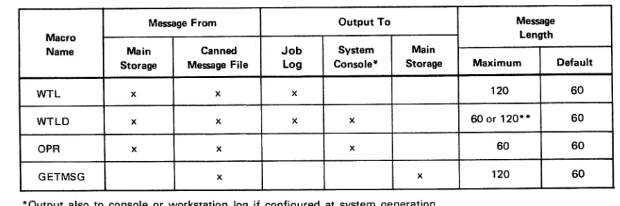
MESSAGE AND LOGGING MACRO INSTRUCTIONS Write to the Log
Display a Message and Write to the Log Get a Canned Message
10.3. 10.3.1. 10.3.2. (WTL) (WIlD) (GETMSG) 11.1. 11.1.1. 11.1 .1 .1.
11.1 .1.2. 11.1.1.3. 11.1.1.4. 11.1 .1 .5.
11.1.2. 11.1.3. 10—17 10—17 10—19 11—1 11—1 11—1 11—2 SPOOLING General Initialization Input Reader Spooler Output Writer Special Functions To Use Spooling
Create a Breakpoint in a Spool Output File
JOB ACCOUNTING General
Accounting Data Job Step Level Data Job Level Data Data Printout
SYSTEM ACTIVITY MONITOR General
Monitor
Report Producing Program
System Activity Monitor Statistics
(BRKPT)
INDEX
3—6 3—1. 9000 Series Assembler Coding Form
Relationship of Basic PIOCS Macro Instructions
Buffer Control Word (BCW) Format for Integrated Disk Adapter Buffer Control Word (BCW) Format for Integrated Peripheral Channel Buffer Control Word (BCW) Format for Multiplexer Channel
Channel Command Word (CCW) Format for Selector Channel Channel Address Word (CAW) Format
Command Control Block (CCB) Format
Physical I/O Control Block (PIOCB) and File Control Block (FCB) Format Tape Block Number Field Format
Partition Control Appendage (PCA) Table Format Record Formats for Disk Devices
8075 Rev. SPERRY UNIVAC Operating System/3 Contents 9
UP-NUMBER UPDATE LEVEL PAGE
Define the File (DTF) Table Format
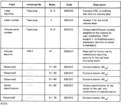
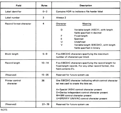
Tape Volume 1 (VOL1) Label Format for an EBCDIC Volume First File Header Label (HDR1) Format for an EBCDIC Tape Volume Second File Header Label (HDR2) Format for an EBCDIC Tape Volume Tape File EOF1 and EOV1 Label Formats for EBCDIC Tapes
Tape File EOF2 and EOV2 Label Formats for EBCDIC Tapes Reel Organization for EBCDIC Standard Labeled Tape Volumes Containing a Single File
6—12. Reel Organization for EBCDIC Standard Labeled Tape Volume: M ultifile Volume With End-of-File Condition
6—13. Reel Organization for EBCDIC Standard Labeled Tape Volumes: Multifile Volumes With End-of-Volume Condition
6—14. Reel Organization for EBCDIC Nonstandard Volumes Containing a Single File 6—15. Reel Organization for EBCDIC Nonstandard Multifile Volumes
6—16. Reel Organization for Unlabeled EBCDIC Volumes
6—17. Tape Volume 1 (VOL1) Label Format for an EBCDIC Volume With Block Numbers 6—18. First File Header Label (HDR1) Format for an EBCDIC Tape Volume With
Block Numbers
6—19. Second File Header Label (HDR2) Format for an EBCDIC Tape Volume With Block Numbers
6—20. Tape File EOF1 and EOV1 Label Formats for Block Numbered EBCDIC Files 6—21. Tape File EOF2 and EOV2 Label Formats for Block Numbered EBCDIC Files
7—1. Event Control Block (ECB) Format 7—8
Examples of GETIME Macro Instruction Example of SETIME Macro Instruction Register Save Area Format
Example of Program Check Island Code Linkage Using Symbolic Addresses Example of Program Check Island Code Linkage Using Register Addresses Example of Abnormal Termination Island Code Linkage Using Symbolic Addresses
8—7. Example of Interval Timer Island Code Linkage Using Symbolic Addresses 8—8. Example of Operator Communication Island Code Linkage Using Symbolic
Addresses
8—9. Example of Operator Communication Island Code Linkage Using Register Addresses
8—10. Example of Discrete Program Check Island Code for Each Task in a Job Step 8—11. Example of Common Program Check Island Code for All Tasks in a Job Step
9—1. Monitor Input Format 9—29
10—1. Canned Message Buffer Formats
10—2. Insertion of Variable Characters in a Canned Message
Relationship of Spooling Devices and Programs Job Accounting Table Format
Job Accounting Record Printout Format
TABLES
3—1. Supervisor Macro Instructions 3—10
6—1. Tape Volume 1 (VOL1) Label Format, Field Description for an EBCDIC Volume
8075 Rev.3 SPERRY UNIVAC Operating System/3 Contents 10
UP-NUMBER UPDATE LEVEL PAGE
6—2. First File Header Label (HDR1), Field Description 6—31 6—3. Second File Header (HDR2), Field Description 6—33 6—4. Tape File EOF1 and EOV1 Labels, Field Description 6—35 6—5, Tape File EOF2 and EOV2 Labels, Field Description 6—37
8—1. Register Save Area 8—29
9—1. Checkpoint/Restart Error Codes 9—13 9—2. Summary of Actions and Program Information Printed 9—45 9—3. Summary of System Debugging Aids 9—46
10—1. Summary of Message Macro Instructions 10—2
8075 Rev. 3 SPERRY UNIVAC Operating
Systeml3
1—1UP-NUMBER UPDATE LEVEL PAGE
1. Concept and Organization
1.1. GENERAL
The SPERRY UNIVAC Operating System/3 (OS/3) Supervisor (supervisor) is the component
that operates with problem programs (user programs) to provide the central control necessary
for optimum and continuous utilization of the system hardware and software. It provides the control, interface, coordination, and allocation of hardware and controlsthe initiation, loading, executing, and termination of user jobs. The efficient and flexible capabilities provided by the supervisor are particularly useful for small to medium sized disc-oriented computing systems. Within the context of this manual the following definitions apply:
Job
A total processing application comprising one or more processing steps. Each job is divided into job steps (programs) that are executed serially. With the exception of disk space, resources are allocated on a job basis.
Job Step
The unit of work associated with one processing program. Ajob step is an executable program consisting of one or more tasks that requires a specific amount of the hardware resources of the system.
Task
A unit of work capable of competing with other tasks for control of the central processor. A task
is
a logical point of control rather than a physical set of instructions. Each job step has at least one task and may create additional tasks (subtasks) all of which compete independently for processor time.Multitasking
The concurrent processing of manytasks asynchronously. Multitasking applies to the switching of processor control among two or more tasks on a priority or rotational basis. Job steps with more than one task are capable of using multitasking. Mu Itijobbing
8075 Rev. 3 SPERRY UNIVAC Operating
Systeml3
12UP-NUMBER UPDATE LEVEL PAGE
1.2. FEATURES
1.2.1. Modularity
The supervisor is designed around control modules, each representing functions or services to be provided. At system generation time, a supervisor program is produced with modules modified and combined to provide the specific combination of capabilities to meet the requirements and restrictions of the particular user installation and applications.
1.2.2. Minimum Main Storage Requirements
The modular design of the supervisor keeps the resident main storage requirement to a minimum. Modules that are frequently used and constitute an integral part of the supervisor are called resident routines because they require permanent residence in main storage. Modulesthat are not continuously required and are nottime critical to normal job execution are called transient routines and are kept on the system resident disk storage These transient routines are located and loaded from disk into main storage only when needed, and executed as an extension of the requesting program
The following modules are always part of the resident supervisor(except for timer and day clock services which are optional):
Supervisor Interface
The points at which control is passed to the supervisor by means of the supervisor call (SVC) instruction interrupt.
Task Switcher
The hub of the supervisor this routine controls allocation of the processor based upon internal priorities.
Transient Management
Schedules, locates, and loads the noncritical transients which perform the nonresident supervisor functions.
Supervisor Overlay Scheduler
Schedules critical supervisor overlays, Physical Input/Output Control
Controls the dispatching, queueing, and interrupt processing for all I/O devices directly connected to the system
Timer and Day Clock Services
Provides system clock and timer activities control. Error Control
8075 Rev. 3 SPERRY UNIVAC Operating System/3
UP-NUMBER UPDATE LEVEL PAGE
Other modules may be selected for inclusion within the resident supervisor at system generation. Such modules as clock control will be either resident or not available; whereas, most modules will be either resident or transient, depending upon system generation options.
1 .2.3. Multijobbing and Multitasking Capability
The supervisor provides multijobbing and multitasking capability through the submission of job control streams which represent the jobs to be performed. In multijobbing environments, from one to seven user jobs may be executed concurrently, with the jobs consisting of a series of job steps (programs). The job steps are executed in a serial manner within each job. Job steps may have from 1 to 256 tasks capable of executing concurrently with other tasks within the job step or system.
1 .2.4. Minimum Operator Intervention
8075Rev.3 SPERRY UNIVAC Operating System/3 21
UP-NUMBER UPDATE LEVEL PAGE
2. Supervisor Interfaces
2.1. INTERRUPT HANDLING
The OS/3 Supervisor is informed of an event, either within the supervisor complex or external to it, by an interrupt, Interrupts may be enabled (allowed> or disabled (held pending) to avoid simultaneous interrupts and to service interrupts based on their relative priorities. Upon recognizing an interrupt, the executing task is suspended and program control is transferred to the appropriate interrupt handler, The interrupt handler analyzes the cause of the interrupt and activates the appropriate interrupt servicing routine.
There are six classes of interrupts by which control is returned to the supervisor: • Supervisor call
• Interval timer • Input/output • Program errors • Hardware errors • Operator request
Of these six, the supervisor call and operator request interrupts provide the user with an interface to the supervisor and, therefore, the operating system. The rest of the interrupts are handled by the specific routines which are described on the following pages.
Tasks have access tothe supervisorvia the supervisorcall (SVC) instruction which is generated within system macro instructions. These supervisor macro instructions provide the access and generate the parameter list associated with the desired function.
8075 Rev. 3
SPERRY UNIVAC Operating System/3 22
UP-NUMBER UPDATE LEVEL PAGE
2.2. MODULAR FUNCTIONS
2.2.1. Task Control
Up to seven user jobs can be activated by the job scheduler for concurrent execution. Job steps
consist of one or more tasks which are asynchronously executed based on internal priority.
Each job step has one primary task generated by the system. This task is deleted at the
termination of the job step. When it is desirable to establish additional tasks for the program, supervisor requests are provided to attach additional tasks. Facilities to synchronize and detach tasks are also provided.
The allocation of processor time to a task is based on a system switch list which contains
information about switching priorities. The number of priorities is a parameter in the supervisor generation (SYSGEN).
2.2.2. Physical Input/Output Control
The physical input/output control system (PIOCS) is structured in function-oriented modules. This allows a user to have the minimUm usage of resident main storage needed for a particular
configuration. The following is a brief description of the functions performed by each of these modules.
2.2.2.1. Execute Channel Program Processor Module
The execute channel program (EXCP) processor is a primary module of PIOCS together with the
hardware interrupt processor. These modules access the remaining functional modules to complete their task.
The EXCP module receives control from the SVC decode routine, validates the request, queues
the request, and conditionally executes the request based on channel anddeviceavailability.
The modules accessed by the EXCP processor include the relocation module, the physical unit block (PUB) control module, the queue control module, and the various channel scheduler
modules.
In the case of certain error conditions, it relinquishes primary control to the hardwarejnterrupt
module.
The diagnostic adapter module interface and the error logging module interface is optional.
The standard entrance to the EXCP module is the SVC interrupt routine processing the EXCP
imperative macro instruction.
The standard exit of the module is the switcher.
The module exits to an error control routine in the event of a failure in the validation checks
8075Rev. 3 SPERRY UNIVAC Operating
Systeml3
2—3UP-NUMBER UPDATE LEVEL PAGE
The module accesses various special purpose modules in performing its function. These modules include:
• Physical unit block (PUB) control module
This module is accessed when the request is first submitted to validate the existence of the device being called. It is also accessed after retrieval of a CCB from the I/O queue. This is to validate that the contents of the CCB have not been inadvertently altered in the interim period between the time it is first submitted and the time it is retrieved from the I/O queue for execution.
• Queue control module
This module is accessed by the EXCP module to place the request in the I/O queue; to retrieve a request from the I/O queue; and, in the case of program errors detected by the channel schedulers, to delete a request from the I/O queue.
• Channel scheduler modules
There is a unique module for each channel type which performs the functions necessary to prepare a request for the start I/O operation. This includes the set-up of the low storage buffer control words (BCW) and the command address word (CAW),
2.2.2.2. PUB Control Module
The PUB control module has a number of primary functions: • Verification of a PUB associated with a CCB
• Location of the device associated with a hardware interrupt
• Location of the device associated with the execution of an REXCP imperative macro (answered operator communication)
• Location of a device with an interrupt held in abeyance in a communication environment
2.2.2.3. Queue Control Module
The queue control module is responsible for the maintenance of the queue list module. This includes adding to the I/O queues, searching and retrieving from the I/O queues, and deletion from the I/O queues. A queue head address is maintained for the system and each job for each I/O path (i.e., integrated disk adapter, each selector channel, each integrated peripheral subchannel, and each multiplexer subchannel). Requests are queued first-in, first-out by priority within the queue for the job. Retrieval from a given job queue is in the sequence in which the CCBs are queued.
8075 Rev. 3 SPERRY UNIVAC Operating System/3 2—4
UP-NUMBER UPDATE LEVEL PAGE
2.2.2.4. Address Adjustment Module
The CCW data address adjustment module converts all addresses in a command chain to absolute form prior to issuance of the start I/O (SIC) command to the hardware. The addresses are converted to relative form prior to returning the command chain to the caller. The module is accessed by the selector scheduler module to create absolute addresses, and by the selector interrupt module to create relative addresses.
2.2.2.5. Channel Scheduler Modules
The various channel scheduler modules prepare a command for execution on a particular channel. This function includes thevalidation of the command as it applies to a unique channel, and the preparation of the channel’s fixed low order storage locations. Additionally, they present a transparent interface to systems users. The integrated channel format is converted to multiplexer or selector channel format.
2.2.2.6, Interrupt Module
The interrupt modules perform processing common to the handling of all interrupts. These functions include:
accessing the I/O status tables (lOST) for an interrupt to be processed;
accessing the PUB control module for the device associated with the interrupt;
transferring control to the particular channel interrupt processing for further processing of solicited interrupts;
alerting the console manager for console unsolicited interrupts;
alerting automatic volume recognition (AVR) for other unsolicited interrupts; processing of answered console error communications for I/O; and
final processing of a CCB, which includes posting the CCB and transferring control to the EXCP processing module for further commands.
2.2.2.7. lOST Processor Module
8075Rev.3 SPERRY UNIVAC Operating System/3 2—5
UP-NUMBER UPDATE LEVEL PAGE
2.2.2.8. Channel Interrupt Processor Modules
The various channel interrupt processor modules perform functions unique to particular channels. They also access the common error control module on the occurrence of an error condition.
2.2.2.9. Error Control Module
This module performs error processing functions common to all error conditions. This includes processing an error action table of a particular channel and alerting the error editing transient when an operator communication becomes necessary.
2.2.2.10. Error Editing Root Overlay
This overlay performs preliminary processing common to all I/O error messages to the operator. The device and channel address, the device status, the channel status, and the sense information are prepared in a canned message format. The reply options are validated and prepared. The appropriate device or channel error mnemonic sense analysis is then called as an overlay.
2.2.2.11. Device Sense Analyzer Overlay
These various critical overlays convert the sense information of a particular error into an English language message to the operator. The operator communication critical overlay is then called to output the message to the operator.
2.2.2.12. Error Reply Overlay
This overlay processes an answered I/O error communication to the operator. It validates the reply and prepares resident control to perform final processing of the message reply.
2.2.3. Transient Management
Transient management consists of two routines, the transient scheduler and the transient loader. The transient scheduler receives control and executes as a supervisor criticalfunction. It allocates a transient area and schedules the transient loader to receive control as the task associated with this transient area. The transient loader computes the disk address based upon the transient identifier and initiates a read of the transient. Upon normal completion of the read, control is passed to the transient.
The transients will either request the overlay of themselves with subsequent phases or release the area when finished processing. The transient loader performs the read of the overlay or yields control to the task switcher.
System/3
LEVELj PAGE
2.2.4. Console Management
Console management provides for the displaying of messages on the CRT screen with responses and commands coming from the operator. The screen images are rolled upward with new display lines or operator input appearing on the bottom of the screen. These routines selectively delete messages not requiring responses from the top of the screen.
Console management is nonresident and is loaded as an overlay when requested. These requests come either as an SVC instruction from a program or as an attention interrupt from the operator.
2.2.5. Workstation Manager
The workstation manager provides the interface between the physical input/output control
systemand the workstation user. Workstations operate in either a workstation mode or system
mode, In the workstation mode, the workstation operator communicates with a program to
which the workstation has been allocated. In the system mode, the workstation communicates with the operating system. Mode selection is made from the workstation. However, a request for mode change may be initiated by the system. When operating in the system mode, the top two lines displayed on the workstation screen are dedicated for messages. Workstation messages to the system are displayed on the first line and system messages to the workstation
on the second line. In the system mode, an interface similar to that of a system console is
provided to the workstation user.
2.2.6. Resource Allocation
Resources are allocated by the supervisor or job control on a job basis. Main storage and
devices are allocated at job initiation for the job’s duration. Normally, disk storage should be allocated at job initiation. However, the capability is provided to allocate or extend permanent and temporary files on a dynamic basis during execution of a job step.
Disk space management routines provide an efficient and completely automatic space accounting and maintenance feature, which relieves you of the responsibility of knowing the precise contents of disk volumes. The routines also permit resolution of competing demands for allocation and establishment of standard interfaces.
Disk space management consists of service routine sets that allocate space to files on disk volumes. This is accomplished by maintaining the volume table of contents (VTOC), through standard procedures, for all files: system, temporary, and permanent.
8075 Rev. SPERRY UNIVAC Operating
Systeml3
2—7UP-NUMBER UPDATE LEVEL PAGE
Devices are allocated to job steps and particular volumes as the job steps are initiated The supervisor is not involved in device allocation to jobs.
2.2.7. Timer and Day Clock Services
The system hardware contains a high resolution timer. An interface is provided to allow a task to request an interrupt after any time period greater than 1 millisecond. The calling task may specify the wait interval in milliseconds or seconds.
The time of day is provided by a simulated day clock. In addition to providing the time to programs upon request, this time is used by the supervisor for time stamping of log messages and job accounting entries.
2.2.8. Program and Machine Error Control
Any error which causes a program interrupt is examined to determine the type of interrupt with the appropriate action being taken.
An interface is provided for processing error information by means of user-supplied island code. Island code is a closed subroutine, having the entry point defined to the supervisor by various action macro instructions, and is given control upon the occurrence of certain contingencies. Standard actions are initiated in the absence of user code. If the unrecovered error is in the system the system will terminate that task which initiated the action resulting in the error.
If any requester of a supervisor function provides a set of parameters which are inconsistent or invalid, the requester is abnormally terminated.
2.2.9. Spooling Operations
The supervisor uses a spooling technique which consists of a set of routines that buffer data files for low speed input and output devices to a direct access storage device. There are three types of routines used for spooling operations: job control stream and card disk readers, supervisor printer/punch spooling cooperative, and output printer/punch writers. In addition, you can utilize the data conversion utilities for converting slow speed media to high speed devices or reverse.
Output writers are provided for online devices, as well as those used in a remote batch environment. This allows user jobs to be unaware of whether they are operating with real devices or spooled files.
8075Rev.3 SPERRY UNIVAC Operating System/3 28
UP-NUMBER UPDATE LEVELJ PAGE
2.2.10. Diagnostic and Debugging Aids
Diagnostic and debugging aids provided in the supervisor include monitor mode, snapshot display of main storage, main storage dumps, standard system error message interface, uniform error responses to user programs and program checkpoint restart. Descriptions of these aids are provided in the following subsections.
2.2.10.1. Monitor and Trace
The monitor routine enables you to trace the execution of a program by a hardware monitor interrupt so that errors can be located and corrected. You can monitor an entire
task or part of a task. In your input to the monitor routine, you can specify actions to be
performed at specific points in the program. The monitor routine interrupts each
instruction before it is executed and tests for the conditions specified in your monitor
input. For each condition, you can request a monitor printout of current program information (PSW contents, next instruction to execute, etc), and continue program execution under monitor control, suspend program execution, or continue program execution without monitor intervention.
2.2.10.2. Snapshot Display of Main Storage
The capability is provided for requesting a partial storage printout at given points in a program by means of a SNAP or SNAPF macro instruction within the program itself. It is also possible to enable or disable these dumps at run time by means of job control. This enables a program to be tested without recompilation to include and disable SNAP or SNAPF requests.
2.2.10.3. Main Storage Dumps
A main storage dump may be provided for programs under the following conditions:
Abnormal termination dump for user job provides a main storage dump of the region in
hexadecimal plus a formatted display of error codes, job-oriented tables, and supervisor information to assist the user in debugging.
Program or operator request dump provides an orderly capability for the operator or any program to request a main storage dump in the same format as the normal termination dump.
8075 Rev. SPERRY UNIVAC Operating System/3 A 2—9
UP-NUMBER UPDATE LEVEL PAGE
2.2.10.4. Standard System Error Message Interface
An error message service routine provides complete and specific error messages without requiring each system module to contain alphanumeric error information. This routine locates the message in a disk file and transfers control to the system console handler for message display or system logging.
2.2.11. Automatic Volume Recognition
Automatic volume recognition allows the console operator to premount magnetic tapes and disk packs before the devices are required for a job step. This reduces time lost due to job step setup and console responses. The automatic volume recognition function is performed during supervisor initialization and as a result of an attention interrupt being received from an online I/O device. This attention interrupt is caused by physically activating the device online, or, in the case of a device that does not have an attention interrupt capability, by the operator issuing an AVR console command.
Using the physical unit block (PUB) for the devices, automatic volume recognition checks to see if the required tape and disk volumes are already mounted. In addition, it performs special processing to handle unique characteristics of various devices. For example, when required at supervisor initialization, it distinguishes between an 8418 disk pack with high density and an 8418 disk pack with low density or an 8416; it performs special interrupt processing for the 841 5 disk; it identifies an 0776 printer configured as an 0770 printer. It then marks the device type in the PUB for that device. It also distinguishes between block numbered and unnumbered tapes. If a tape is not at Ioadpoint, it rewinds the tape so that
it can read the label and the volume serial number.
The automatic volume recognition function displays console messages to the operator to indicate such conditions as a disk or tape not prepped, an I/O error, or a duplicate volume serial number.
A system generation option incorporates a retry on the attention interrupts feature in the AVR function. This permits automatic retry of a recoverable error when an attention interrupt is received on a printer, card reader, or card punch that has an unanswered PIOCS error message. The operator can initiate the recovery retry at the device by placing it online, instead of having to return to the console to respond to the error message.
2.2.12. Main Storage Consolidation
Main storage consolidation is a system generation option that repositions jobs and
8075 Rev. SPERRY UNIVAC Operating
Systeml3
2—10UP-NUMBER UPDATE LEVEL PAGE
When a job or a symbiont terminates, the next job to be run is evaluated to determine
whether there is enough space available or whether main storage consolidation is
necessary and which jobs must be moved. If this job is scheduled and consolidation is required, the jobs are moved down one by one, starting with those farthest from the supervisor. Each job to be moved is brought to an idle state, then moved down. Addresses are adjusted and the job is reactivated. When all these jobs have been moved, the next scheduled job is read in and initiated.
Main storage consolidation does not move symbionts because they do not have an associated relocation register. Nor does main storage consolidation move jobs with open interfaces to the integrated communications access method (ICAM), because these jobs may be reading or writing directly into or out of user main storage. This restriction is minimized if ICAM is loaded first, then ICAM user jobs next, in order to retain the maximum continuous main storage region for further allocation.
2.2.13. Rollout/Rollin
The rollout/rollin function is a system generation option that temporarily transfers jobs-from main storage to disk to make room for a job with a preemptive scheduling priority. Jobs currently in main storage are suspended and written to the job’s run library. The preemptive job is then read into main storage and initiated. As enough space becomes available, the rolled-out jobs are read back into main storage and allowed to continue processing.
When a job or a symbiont terminates and there is a preemptive job in the job queue the preemptive job is evaluated to determine whether there is enough existing main storage available, or whether main storage consolidation or rollout is necessary to make space available. If the job is scheduled and rollout is required, the rollout function brings each job marked for rollout to an idle state, delinks the TCBs from the switch list, and writes the job’s image from the job region to disk. These rolled-out jobs have asterisks appended to their names on the top line of the display on the system console. If the needed I/O devices are available, the preemptive job is read into the freed main storage and initiated.
As space becomes available and if there are no other preemptive jobs, the job scheduler tries to bring in the rolled-out jobs one by one The job slots and I/O devices remain in effect from the time the jobs were rolled out. The job scheduler ignores any jobs on the high- or normal-priority job queues until all of the rolled-out jobs have been rolled back in and reactivated.
2.2.14. Cochanneling
Cochanneling is the capability of accessing a single peripheral device through either of two physica[ paths. Under OS/3, it provides for the support of both the dual access and dual channel capabilities of the 90/30 hardware.
Dual access cochanneling permits simultaneous I/O operations (read/read, read/write,
write/write) on any two devices using two control units and two selector channels. Each
input/output device is connected to both control units, one control unit on each selector
8075 Rev. 3 SPERRY UNIVAC Operating System/3 2—11
UP-NUMBER - UPDATE LEVEL PAGE
SPERRY UNIVAC 8414, 8424, 8425, 8430, and 8433 Disk Subsystems and UNISERVO 10, 12, 16, and 20 Magnetic Tape Subsystems on selector channels.
Dual channel cochanneling provides for nonsimultaneous access to a single control unit from either of two selector channels. The devices are connected to one control unit, which is connected to both selector channels. When one channel is busy, the second channel is used to access the device, thereby avoiding a waitfor the busy channel. Depending on the control units used, dual channel cochanneling is applicable to SPERRY UNIVAC 8414, 8424, 8425, 8430, and 8433 Disk Subsystems, and UNISERVO 10, 12, 14, 16, and 20 MagneticTape Subsystems on selector channels.
2.2.15. Disk Seek Separation
This feature provides for the execution of seek commands to the requested devices before executing the data transfer command, thereby freeing the I/O channel during the device positioning time. This is accomplished by executing seek commands to all devices that have queued requests whenever the channel is free (channel end status received). The data transfer (reads and writes) on the channel are executed as soon after the positioning of the head (device end status) is completed.
Seek separation will increase the number of I/O requests that can be completed in a given time frame when multiple devices are in use on a channel. It will not change the sequence of a job I/O request, but it may change the sequence of various job I/O requests with regard to execution.
2.2.16. Error Logging
The error logging function records hardware errors for later statistical and historical use by Sperry Univac customer engineers. It is a default feature of all OS/3 supervisors above the minimum PIOCS configuration and can be turned on and off, and suspended and resumed, by system console commands. At the time the error occurs, pertinent information is stored temporarily in the error log file on the system resident volume. The customer engineer can read these records from the error log file into main storage for processing and permanent record, assisting him in maintaining customer equipment.
2.2.17. Interactive Services
If your OS/3 system has workstations, they can be used as input and output devices by means of interactive services. This feature lets you use workstations with either system or user programs. These services include:
• Interactive job control
• Interactive data utilities
• General editor
8075 Rev. 3
UP-NUMBER SPERRY UNIVAC Operating System/3 UPDATE LEVEL PAGE
3.1. GENERAL
3. Macro Instruction Conventions
The OS/3 provides a complement of macro instructions to facilitate service requests between a user program and the supervisor. This set of macro instructions is available only when using the assembler language and cannot be directly evoked when using
-higher-level languages.
Conventions used in this manual to illustrate the supervisor macro instruction formats and some general rules for writing macro instruction statements are contained in 3.2.
General rules and conventions for writing programs using the SPERRY UNIVAC 9000 Series assembler coding form are contained in 3.3.
3.2. FORMAT ILLUSTRATION AND STATEMENT CONVENTIONS
The general format of a macro instruction is:
n A symbolic name can appear in the label field. It can have a maximum of eight characters and must begin with an alphabetic character.
m The appropriate macro instruction mnemonic must appear in the operation field and identifies the operation or service requested.
• When parameters are specified in the operand field, they must be positional parameters or keyword parameters as required by the particular function.
• Parameters must not be separated by blanks.
• Assembler rules regarding blank columns and continuation of the operand field must be followed
LABEL tOPERATI0N symbolic
name
macro mnemonic
8075 Rev. 3
SPERRY UNIVAC Operating
Systeml3
3-2UP..NUMBER UPDATE LEVEL PAGE
The conventions used to delineate the supervisor macro instructions are as follows:
• Capital letters, commas, parentheses, and equal signs must be coded exactly as
shown.
Examples:
R ALL (1) SIZE=
• Lowercase letters and words are generic terms representing information that must be
supplied by the user. Such lowercase terms may contain hyphens and acronyms (for
readability) Acronyms that form part of the variable symbolic name remain
capitalized.
Examples
symbol start-addr
number-of-bytes param-1
CCB-name
• Information contained within braces represents mandatory entries of which one must
be chosen.
Examples:
(PC IT
tAB
$
input-area‘I. (1)
• Information contained within brackets represents optional entries that (depending
upon program requirements) are included or omitted. Braces within brackets signify that one of the specified entries must be chosen if that parameter is to be included
Examples:
[,entry-nurnber] [,R]
CCB-name
HALL
}
L
(18075 Rev. 3 SPERRY UNIVAC Operating System/3
UP-NUMBER UPDATE LEVEL PAGE
The optional entries (1) and (0) refer to registers 1 and 0. The optional entry (r) refers to a register (other than 1 or 0) to be designated by you in the macro instruction statement. For example, the instruction:
LABEL LOPERATIONt OPERAND
1 10 16
I
ISpecifies the input area (positional parameter 1) as WORK and the error address (positional parameter 3) as ERRADDR. It also specifies that, at the time this macro instruction is executed, register 0 will contain the number of records to be read (positional parameter 2).
Note the use of the shaded entry 1, which means that an entry of one as the number of records is assumed if you omit positional parameter 2; and the shaded entry 80, which means a record image of 80 bytes is to be read if you omit positional parameter 4.
3.3. USE OF THE ASSEMBLER CODING FORM
To convert your written program to a form that can be conveniently inputted to the computer, your written work is keypunched into 80-column cards. To make the job of the programmer, keypunch operator, and any other person who may reference this program easier, there are conventions for writing and reading programs and reference materials. A useful tool is the 9000 Series assembler coding form. (See Figure 3—i.)
Theoretically, you could write your program on a plain sheet of paper, as long as you observe the assembly language formatting rules. Using an assembler coding form, however, will ease the job, both for you and for the keypunch operator, who must prepare the punched card deck from your written program.
8075 Rev. 3
SPERRY UNIVAC Operating System/3 3—8
UP-NUMBER
UPDATE LEVEL PAGE
-3.3.6. Sequence Field
Columns 73 through 80 may be used for entering sequence numbers. This is done by assigning consecutive numbers to each line of coding and is useful for reassembling the card deck if it should be dropped. It is good practice to number the lines in multiples of 10,
or even 100. This allows you to insert additional coding lines without having to renumber
the cards when they have been keypunched prior to the modification. Some programmers use letters in addition to the numbers. This is useful in identifying the deck from which cards have come if they have been removed for any reason.
3.4. MACRO INSTRUCTIONS
3,4.1. Declarative Maàro Instructions
Declarative macro instructions generate nonexecutable code sequences in the user
program and are used to allocate areas in main storage containing control information for various system services.
3.4.2. Imperative Macro Instructions
Imperative macro instructions generate executable code sequences in the user program. These code sequences make up the interface between the user program and the supervisor. Imperative macro instructions are used to request services of the supervisor or to direct the operation of the user program.
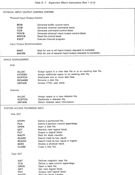
3.4.3. Summary of Supervisor Macro Instructions
Table 3—i. is a list of the OS/3 supervisor macro instructions and a brief statement of the service performed by each. In this list, ARGLST, BCW, CCW, CCB, PIOCB, DTFPF, PCA,
SAT, TCA, ECB, DDCPF, and DCFLTare declarative macro instructions; the remainder are
imperative macro instructions. Complete descriptions of the macro instructions are
contained in Sections 4 through 11 of this manual in the same functional groups as indicated in the table.
3.5. PROGRAMMING CONSIDERATIONS FOR MACRO INSTRUCTIONS
8075 Rev. 3 SPERRY UNIVAC Operating
Systeml3
UP-NUMBER UPDATE LEVEL PAGE
A macro instruction, especially if it is a request to the supervisor for some service, will usually generate a supervisor call (SVC) instruction. When the program is later executed, the SVC will either be processed by the resident supervisor, or a transient will be called. The actual processing of the request is then performed by the supervisor; the inline expansion code generated by your program is normally just used to set up parameters. Because SVC instructions are processed in the supervisor region and not in your program region, you can use macro instructions freely, without having to allocate extra main storage to your job.
LATE
PAGETable 3—1 Supervisor Macro Instructions (Part 1 of 3)
PHYSICAL INPUT/OUTPUT CONTROL SYSTEM
Physical Input/Output Control
BCW Generate buffer control word. CCW Generate channel command word, CCB Generate command control block.
PIOCB Generate physical input/output control block, RDFCB Read file control block.
EXCP Execute channel program. Input/Output Synchronization
WAIT Wait for one or all input/output requests to complete. WAITM Wait for one of several input/output requests to complete. SPACE MANAGEMENT
Disk
ALLOC Assign space to a new disk file or to an existing disk file. EXTEND Assign additional space to an existing disk file.
SCRTCH Deallocate one or more disk files. RENAME Rename a disk file.
OBTAIN Access VTOC user block. Diskette
ALLOC Assign space to a new diskette file. SCRTCH Deallocate a diskette file.
OBTAIN Obtain diskette label information. SYSTEM ACCESS TECHNIQUE (SAT)
Disk SAT
DTFPF Define a partitioned file.
PCA Define a partition control appendage. OPEN Open a disk file,
GET Retrieve next logical block. PUT Output a logical block. WAITF Wait for block transfer. READE Search track by key, equal.
READH Search track by key, equal or higher. SEEK Access a physical block.
CLOSE Close a disk file, Tape SAT
SAT Defines magnetic tape file. TCA Define a tape control appendage. OPEN Open a tape file.
8075 Rev.3 SPERRY UNIVAC Operating System/3 A 3—11
UP-NUMBER UPDATE LEVEL PAGE
Table 3—1. Supervisor Macro Instructions (Part 2 of 3)
MULTITASKING
Task Management
ECS Generate an event control block. ATTACH Create and activate an additional task. DETACH Terminate a task normally.
TYIELD Deactivate a task.
AWAKE Reactivate an existing nonactive task. CHAP Change the priority of a task.
Task Synchronization
WAIT Wait for a task request to complete.
WAITM Wait for one of several task requests to complete. POST Activate the waiting task.
TPAUSE Deactivate one or more tasks other than the issuing task. TGO Reactivate one or more tasks other than the issuing task. PROGRAM MANAGEMENT
Program Loader
LOAD Load a program phase and return control.
LOADR Load a program phase, relocate address-constants, and return control. LOADI Locate a program phase and store its phase header in a work area. FETCH Load a program phase and branch.
Job and Task Termination
EOJ Terminate a job step normally. CANCEL Terminate a job abnormally.
Timer Services
GETIME Obtain current time and date.
SETIME Set an elapsed time counter for the requesting task.
Program Linkage
CALL/VCALL Call a program.
ARGLST Generate an argument list. SAVE Save register contents. RETURN Restore registers and return. Island Code Linkage
8075 Rev. SPERRY UNIVAC Operating System/3 3—12
UP-NUMBER UPDATE LEVEL PAGE
Table 3—i. Supervisor Macro Instructions (Part 3 of 3)
PROGRAM MANAGEMENT (cont) System Information Control
GETCOM Retrieve data from job communication area. PUTCOM Place data into job communication area. GETINF Retrieve data from system control tables. Control Stream Reader
GETCS Retrieve embedded data file submitted in job control stream. SETCS Reset pointer to embedded data file.
DIAGNOSTIC AND DEBUGGING Storage Displays
SNAP/SNAPF Print out portions of main storage and return control. DUMP Print out the job main storage and terminate the job step. Checkpoint Facility
+
CHKPT Record a checkpoint. DDCPF Define a SAT checkpoint file. DCPOPN Open a SAT checkpoint file. DCPCLS Close a SAT checkpoint file.4
DCFLT Generate a file list table.Monitor and Trace
1/ OPTION TRACE Monitor from start of job.
(This is a job control statement, not a macro instruction.) MESSAGE DISPLAY, LOGGING, AND OPERATOR COMMUNICATION
WTL Write a message into system log file.
—- WILD Write a message into system log file after displaying on system console or workstation.
GETMSG Retrieve message from canned message file.
OPR Display a message on system console or workstation. OTHER SERVICES
Spooling
8075 Rev. 3 SPERRY UNIVAC Operating Systeml3 A 4—1
UP-NUMBER UPDATE LEVEL PAGE
+
4. Physical Input/Output Control
System (PIOCS)
4.1. GENERAL
The resident supervisor of OS/3 contains a set of routines called the physical input/output control system (PIOCS) that controls the activity between the processor and all peripheral devices connected to the mutliplexer, selector, and integrated channels. These input/output (I/O) channels operate independently of the processor and allow I/O operations on a channel to overlap with processing and with operations on other I/O channels.
PIOCS:
B schedules I/O requests to maintain optimum I/O throughput without burdening the problem program;
• initiates I/O operations;
B tests for error or other exceptional conditions pertinent to the actual physical transfer of data; and
• activates error recovery procedures in the event of peripheral device errors.
Problem program interface to the IOCS
is
provided at two levels: data management (logical I/O control system) and PIOCS macro instructions.Data management routines substantially reduce programming effort, especially for jobs requiring a great amount of I/O processing. The routines, by handling the foregoing I/O functions for the programmer automatically, enable you to concentrate on the logical record, because the applicable PIOCS macro instructions are contained in the data management macro routines and you need only limited knowledge of the peripheral device. The data management macro instructions are described in the data management user guide, UP-8068 (current version>.
8075 Rev. 3 SPERRY UNIVAC Operating
Systeml3
A 4—2UP-NUMBER UPDATE LEVEL PAGE
constructing the actual I/O commands processed bythe device as well as constructing the control blocks used by PIOCS for issuing the I/O order;
• ensuring the desired sequence of I/O commands bythe proper use of I/O synchronization
macro instructions;
• blocking/deblocking logical records;
• alternating I/O buffer areas;
• detecting wrong-length records;
• handling end-of-file (EOF) or end-of-volume (EOV) conditions;
• processing labels;
• translating ASCII data to EBCDIC on input, or EBCDIC data to ASCII on output; and
• handling unique error conditions.
4.2. PHYSICAL I/O CONTROL
4.2.1. General
Detailed tabular information pertaining to each request must be supplied if the problem program is to communicate effectively with the IOCS facilities of the resident supervisor through the PIOCS macro instructions.
The following PIOCS macro instructions are available for establishing the tabular information
and for requesting services of the supervisor and the IOCS:
• Table generation macro instructions (declarative)
BCW
Constructs a buffer control word (BCW), which is used by the integrated I/O channels and multiplexer channel.
ccw
Constructs a channel command word (CCW) which is used by the selector I/O channel and the physical device.
CCB
Constructs a command control block (CCB), which is used as a bidirectional communications medium between the problem program and the IOCS routines in the supervisor.
PIOCB
Constructs a physical input/output control block (PIOCB), which is used as a buffer