Implementation of Distributed Power FlowController to advance
Power Quality
B.Ranjeeth Kumar
M.Tech, Electrical Power Systems
Talla Padmavathi College Of Engineering,Kazipet,Warangal
Mr.D.Bheemaiah
Associate Professor,EEE
Talla Padmavathi College Of Engineering, Kazipet,Warangal
Abstract:In the last few decades the usage of electricpower is increasing day by day, the operation of powermethods has become complex because of developing consumption and multiplied quantity of non-linear loads because of whichcompensation of a couple of power great issues has grow to be a compulsion. As a consequence the power organizations areconcentrating no longer only on variety of the power but additionally the quality of the power with develop in complexity in method.Right here the brand new element within the flexible AC-transmission system (FACTS) household, called distributed power-flow controller (DPFC) is offered in this paper. The important power exceptional problems like voltage sag and swell are studied inthis paper. The DPFC is modified from UPFC, by way of taking away normal DC hyperlink between series and shunt convertersfrom UPFC. The three-phase sequence converter is cut up into number of single-segment series dispensed converters throughthe line. The energetic energy is exchange between the series and shunt converter at third harmonic frequency by way oftransmission line in DPFC.The model of transmission line with andwithout DPFC is modelled in MATLAB/Simulink. From the model, it is seen that the power quality improved with thehelp of DPFC with higher controllability and reliability compare to other FACTS devices.
KEYWORDS-FACTS, Distributed Power Flow Controller, Power Quality, Sag and Swell Mitigation.
I. INTRODUCTION
Recent developments in the electric utility industry are encouraging the entry of power quality issue [1]. Extendingfrom the generation units to the utility customers, power quality is a measure of how the elements affect the system asa whole [2]. From
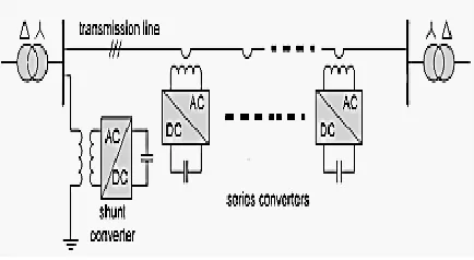
customer point of view, the power quality issue is concerned about current, voltage or frequencydeviation which results in power failure [3]. To solve the power quality problem in such a situation, the powerelectronic devices such as flexible alternating-current transmission system (FACTS) and custom power devices(DVR) which are used in transmission and distribution control, respectively, should be developed [4], [5], [6]. Theimpact of transient parameters in majority of transmission lines problems such as sag (voltage dip), swell (overvoltage) and interruption, are also considerable [1]. To mitigate the mentioned power quality problems, the utilizationof FACTS devices such as power flow controller (UPFC) and synchronous static compensator (STAT-COM) can behelpful [7] , [8]. In [9], the distributed power flow controller (DPFC) is presented which has a similar configuration toUPFC structure. As shown in Fig. 1, the DPFC is composed of a single shunt converter and multiple independentseries converters which is used to balance the line parameters, such as line impedance, transmission angle and busvoltage magnitude [9], [10]. To detect the voltage sags and determine the three single-phase reference voltages ofDPFC, the SRF method is also proposed as a detection and determination method.
P a g e | 3055 The shunt converter is similar tothe STATCOM
while the series converter employs the D-FACTS concept. The DPFC has same capability as UPFC tobalance the line parameters, i.e., line impedance, transmission angle, and bus voltage magnitude [4].
II. DPFC PRINCIPLE
In the Unified Power Flow Controller (UPFC) is structured from SSSC and STATCOM. Both are coupled by DCstorage capacitor via a common DC link. In comparison with UPFC, the main advantage offered by DPFC iseliminating the huge DC-link and instate using 3rd-harmonic current to active power exchange [2]. Theoretically thethird, sixth, and ninth harmonic frequency can be used to exchange active power in the DPFC, which are generally zerosequence frequencies. The capacity of a transmission line to deliver power depends on its impedance. The transmissionline impedance is inductive and proportional to the frequency, so the high transmission frequencies will cause highimpedance. Because of this the third harmonics frequency is selected which is lowest zero sequence harmonicfrequency. In the following subsections; the DPFC basic concepts are explained.A. DC Link Elimination and Power Exchange: In the DPFC, instead of common DC link, the transmission line is usedas a connection between the terminal of series converters and DC terminal of shunt converter, for power exchangebetween converters [2] [6]. The power theory of non-sinusoidal components is used to exchange power in DPFC. Anon-sinusoidal voltage or current can be presented as the sum of sinusoidal components at different frequencies isbased on Fourier series. The multiplication of current and voltage components gives the active power. Since theintegral of some terms with different frequencies are zero, so the active power equation is given as:
∑ ………... (1)
Where and are the voltage and current at the
harmonic, respectively, and is the angle between
the voltageandcurrent at the same frequency. Equation (1) expresses theactive power at different frequency components isindependent.
From the above equation (1), the current and voltage in one frequency has no influence on the active
power at otherfrequencies. The active power at different frequencies is isolated from each other.
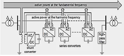
So by this concept the shunt converter in DPFC can absorb active power from the grid at the fundamental frequencyand inject the current back into the grid at a harmonic frequency. Based on this fact, a shunt converter in DPFC canabsorb the active power in one frequency and generates output power in another frequency, and also according to theamount of active power required at the fundamental frequency, the DPFC series converter generate the voltage at theharmonic frequency there by absorbing the active power from harmonic components.
Figure-2: Active Power Exchange
Figure-3: Utilize grounded Y-∆ transformer to filter zero-sequence harmonic
The third-harmonic is selected to exchange the active power in the DPFC and a high-pass filter is required to make aclosed loop for the harmonic current. The third harmonic current is trapped in trapped in Δ-winding of transformer.Hence, no need to use the high-pass filter at the receiving-end of the system. In other words, by using the thirdharmonic, the high-pass filter can be replaced with a cable connected between delta winding of transformer and ground.This cable routes the harmonic current to ground as shown in figure 4.
Figure- 4: Route the harmonic current by using the grounding of the Y-∆ transformer
The DPFC Advantages:
The DPFC has some advantages as comparison to other FACTS devices, given as follows:
i. High Control Capability: The DPFC similar to UPFC, it can control all parameters of transmission network,like transmission angle line impedance, and bus voltage magnitude.
ii. High Reliability: The division of series converters in number of part increases the DPFC reliability duringconverters operation. It means that if one of series converters fails, the others can continue to work.
iii. Low Cost: The single-phase series converters rating are lower than one three-phase converter. Furthermore,the series converters do not need any high voltage isolation in transmission line connecting; single-turntransformers can be used to hang the series converters. Reference reported a case study to explore thefeasibility of the DPFC, where a UPFS is replaced with a DPFC in the Korea electric power corporation[KEPCO].To achieve the same
UPFC control capability, the DPFC construction requires less material.
1. Control Strategies:
The DPFC has three control strategies
a. Central Control: In this control strategy, the reference signal sends by DPFC to both series and shuntconverter. The central control gives corresponding reactive current signal for the shunt converter and voltagereference signals for the series converters as per requirement. All the reference signals are generated bycentral control are at the fundamental frequency.
Figure- 5: Central Controls
P a g e | 3057 Figure- 6: Block diagram of the series converters in
Matlab/Simulink
c. Shunt Control:The shunt converter includes a three-phase converter connected back-to-back to a single-phaseconverter. The three-phase converter absorbs active power from grid at fundamental frequency and controlsthe dc voltage of capacitor between this converter and single-phase one. Other task of the shunt converter is toinject constant third-harmonic current into lines through the neutral cable of Δ-Y transformer.Each converter has its own controller at different frequency operation (fundamental and third-harmonic frequency). Theshunt control structure block diagram is shown in Fig. 7.
Figure- 7: The shunt control configuration(a) For fundamental frequency (b)For third-harmonic
frequency
III. POWER QUALITY
IMPROVEMENT
To find the improvement in power quality by using DPFC, case study of original transmission line from Bhusawal toDhule is taken, which is 220KV 100 KM
line. The system contains a three-phase source connected to a nonlinear RLCload through parallel transmission lines with the same lengths. The DPFC is placed in transmission line, which theshunt converter is connected to the transmission line in parallel through a Y-Δ three-phase transformer, and seriesconverters is distributed through this line. To simulate the dynamic performance, a three phase fault is considered nearthe load. The time duration of the fault is 0.2 seconds [3][8]. The MTLAB simulation model is develop for the line andfind the power quality improvement by DPFC. The MATLAB model with DPFC is shown in fig.8.
Fig.8: MATLAB simulation model of 220KV transmission line with DPFC
IV. CONCLUSION
To improve power quality in the power transmission system, there are some effective methods. In this paper, thevoltage sag and swell mitigation, using a new FACTS device called distributed power flow controller (DPFC) ispresented.The DPFC has a high control capability to balance the line parameters like transmission angle, lineimpedance and bus voltage magnitude. Also the DPFC has some advantages, such as high reliability, high controlcapability and low cost. The DPFC is modelled and three control loops, i.e., central controller, series control, and shuntcontrol are design.
REFERENCES
2. E. Emanuel and J. A. McNeill, “Electric power quality,” Annu. Rev. Energy Environ, 1997.
3. N. R. Patne and K. L. Thakre “Factor affecting characteristics of voltage sag due to fault in the power system,” Serbian Journal of Electricalengineering. vol. 5, no.1, 2008.
4. J. R. Enslin, “Unified approach to power quality mitigation,” in Proc. IEEE Int. Symp. Industrial Electronics (ISIE ’98), vol. 1, 1998.
5. B. Singh, K. Al-Haddad, and A. Chandra, “A review of active filters for power quality improvement,” IEEE Trans. Ind. Electron. vol. 46, no. 5,pp. 960–971, 1999.
6. M. A. Hannan and A. Mohamed, member IEEE, “PSCAD/EMTDC simulation of unified series- shunt compensator for power qualityimprovement,” IEEE Transactions on Power Delivery, vol. 20, no. 2, 2005.
7. L. Olimpo and E. Acha, “Modeling and analysis of custom power systems by PSCAD/EMTDC,” IEEE Trans. Power Delivery, vol. 17, no.1,pp. 266–272, 2002.
8. P. Pohjanheimo and E. Lakervi, “Steady state modeling of custom power components in power distribution networks,” in Proc. IEEE PowerEngineering Society Winter Meeting, vol. 4, Jan, pp. 2949–2954, 2000.
[9] zhihui yuan,sjoerd W.H de haan and Braham Frreira and Daliborcevoric “A FACTS DEVICE: Distributed power flow controller(DPFC) ” IEEE transaction on power electronicsvol.25,no.10october 2010.
[10] zhihui yuan,sjoerd W.H de haan and Braham Frreira “DPFCcontrol during the shunt converter failure” IEEE transaction onpower electronics 2009
Authors:
B.Ranjeeth Kumar pursing M.Tech in