Design And Simulation Of Dvr Using Sinusoidal Pulse Width
Modulation And Hysteresis Voltage Control For Power
Quality Improvement
G.Ujwala
1, Y.Priyanka
2Department of Electrical and Electronics Engineering, G.Narayanamma Institute of Technology & Science Email: [email protected], [email protected]
Abstract: Dynamic Voltage Restorer (DVR) is one of the custom power devices that are used as an effective solution for the protection of sensitive loads against voltage disturbances in power distribution system. The efficiency of the DVR depends on the performance efficiency of the control technique involved in switching the inverters. This paper gives a systematic approach of the design of dynamic voltage restorer using sinusoidal pulse width modulation and unipolar hysteresis voltage control. . DVR is a series connected device used for compensating voltage sags and swells on the distribution side. In this work, a step by step procedure is given to figure out the components that are required for the design and simulation of DVR. The detection of sags/swells is carried out with the help of dqo theory, whereas the control of the voltage source inverter is done with the help of SPWM and bipolar hysteresis voltage control. The simulation of the proposed work is carried out with the help of MATLAB/ SIMULINK and the results were found to be in accordance with theory.
Keywords: Dynamic Voltage Restorer (DVR), Sinusoidal Pulse width modulation (SPWM), Hysteresis voltage
Control, dqo theory,Voltage sag/swell.
1. INTRODUCTION
The term electric power quality (PQ) is generally used to assess and maintain the good quality of power at the level of generation, transmission, distribution, and utilization of AC electrical power. In modern distribution system, there are a number of voltage-based power quality (PQ) problems caused by substantial pollution and abnormal operating conditions. These power quality problems at point of common coupling (PCC) occur due to the voltage drop in feeders and transformers, various kinds of disturbances, faults, use of unbalanced lagging power factor consumer loads, and so on. Some of these voltage-related power quality problems are voltage spikes, surges, flickers, sags, swells, notches, fluctuations, voltage imbalance, waveform distortion, and so on. These power quality problems are classified as voltage and current quality problems in distribution systems. According to IEEE 1159 voltage sag is defined as the decrease in RMS voltage to a level of 0.1 to 0 .9 p.u of nominal value. On the other hand voltage sells are defined to be the short duration increase in RMS voltage to a level of 1.1 to 1.8 p.u. of nominal value. Based on duration sag and swell are classified as instantaneous (½ cycle to 30 cycles), momentary (30 cycles to 3 seconds), and temporary (3 seconds to 1 minute) [1]. Voltage sags are caused by abrupt increase in loads such as short circuits or faults, motors starting, or electric heaters turning on, or they are caused by abrupt increases in source impedance, typically caused by a loose connection. Voltage swells are almost always caused by an abrupt reduction in load on a circuit
with a poor or damaged voltage regulator, although they can also be caused by a damaged or loose neutral connection. These voltage problems can be solved using a series connected custom power device called dynamic voltage restorer (DVR). In this paper, the implementation of DVR and its simulation are discussed in detail. The emphasis has been given for switching control strategy i.e. pulse width modulation scheme and their detailed results are presented.
2. DVR BASICS
2.1 Principle Of DVR
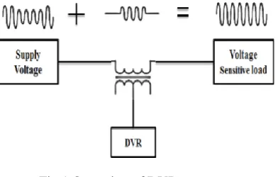
The principle of DVR is simple i.e. whenever the source voltage is unbalanced or distorted the DVR restores the load side voltage to the desired amplitude by injecting a voltage of required magnitude. In other words we can say that the main function of the DVR is to regulate the load voltage In short, the principle of DVR can be explained with the help of the following equation which has to be satisfied for all the time [3].
Fig.1 Operation of DVR
2.2 Operating Modes Of DVR:
The DVR has to work only when there is a sag/swell in the source voltage. Depending on that the operating modes of DVR can be classified as below [4] :
2.2.1 Protection mode:
Whenever there is a fault on the line, very high fault currents will be flowing through the line. Since the DVR is series connected, the fault currents will be flowing through the DVR also which is not desired. The DVR should be protected from these over currents or large inrush currents. The bypass switches remove the DVR from system by supplying another path through switch for current as shown in Fig. 2.
Fig.2. Configuration of switches in protection mode
2.2.2 Standby mode:
In standby mode, the DVR may either go into short circuit operation or inject small voltage to compensate the voltage drop for transformer reactance or losses as shown in Fig. 3. Short circuit operation of DVR is the general preferred solution in steady state.
Fig.3. Configuration of switches in standby mode
2.2.3 Injection mode:
The DVR goes into injection mode as soon as the sag is detected. Three single-phase ac voltages are injected in series with required magnitude, phase and wave shape for compensation. The types of voltage sags, load conditions and power rating of DVR will determine the possibility of compensating voltage sag.
3. FUNDAMENTAL COMPONENTS OF DVR
The fundamental components of DVR are 1. Injection or Booster transformer 2. Harmonic filter
3. Voltage Source Inverter (VSI)
[image:2.612.316.566.211.427.2]4. DC Energy Storage Device and charging circuit 5. Control system
Fig.4. DVR Block Diagram
4. EQUATIONS RELATED TO DVR
The equivalent circuit of DVR is shown in Fig. 5. On detection of any reduction in the supply voltage Vsource from any set value, the DVR injects a voltage, VDVR, in series through the injection
transformer such that the desired load voltage, VLoad
[image:2.612.101.266.398.502.2]can be maintained at the load end.
Fig.5. Equivalent Circuit of DVR
The DVR injection voltage can be written as in equation (1)
VDVR= VLoad+ZLineILoad-VSource --- (1)
Where
[image:2.612.343.550.559.638.2]Zline = Line impedance
Iload = Load current
Vsource = System voltage during any fault
condition
VDVR = DVR injected voltage
In case if the supply voltage is not sagged or swelled then Vload will be equal to Vsource and the DVR injected voltage will be a very small quantity (Zline Iload) which is required to compensate for the line voltage drop.
5. VOLTAGE COMPENSATION METHODS
OF DVR:
Compensation is achieved by real power or reactive power injection. Based on the compensation level required there are three types of compensation methods[6]:
5.1 Presag Compensation:
Non linear loads need both magnitude as well as phase angle compensation. In presag compensation technique DVR supplies the difference between pre-sag and sag voltage restoring the voltage magnitude as well as the phase angle to that of the pre-sag value. Therefore this method is suited for nonlinear loads. However this technique needs a higher rated energy storage device and voltage injection transformers.
5.2 InPhase Compensation:
The DVR compensates only for the voltage magnitude in this particular compensation method, i.e. the compensated voltage has the same phase as that of sagged voltage and it only compensates for the voltage magnitude. Therefore this technique minimizes the voltage injected by the DVR. Hence it is suited for the linear loads, which do not need phase angle compensation.
5.3 Energy-Optimization technique:
In this particular control technique the use of real power is minimized (or made equal to zero) by injecting the required voltage by the DVR at a 90° phase angle to the load current. However in this technique the injected voltage will become higher than that of the in-phase compensation technique. Hence this technique needs a higher rated transformer and an inverter compared with the earlier cases. Further the compensated voltage is equal in magnitude to the presage voltage, but with a phase shift.
6.PROPOSED CONTROL SCHEME
The Control scheme implemented here is with the help of dqo transformation. Once the voltage disturbance occurs, the output of the inverter can be adjusted in such a way that it is in phase with the
incoming ac source while the load voltage is regulated. The output of inverter is equipped with inductors and capacitors for filtering purpose. The role of DVR controller is recognition of voltage sag/swell issues, calculating the compensating voltage, trigger pulse creation for sinusoidal PWM inverter, correction of any errors in the series voltage injection and extinction of the trigger pulses once the fault is cleared.
The simulation block diagram based on dqo theory is shown in fig.6
Fig.6. Simulation Block Diagram
The dqo transformation or otherwise called Park’s transformation is implemented in DVR controller. The quantities are expressed as instantaneous space vectors. The voltage is converted from abc reference frame to dqo reference. We ignore zero sequence components for simplicity. The control is implemented by comparing a set of reference voltage and measured load phase voltages.
The error signal obtained is used as a control signal to generate a sequence pattern for power switches of the voltage source inverter using pulse width modulation technique (SPWM). The phase locked loop (PLL) is used for the generation of a unit sinusoidal wave in phase with mains supply voltage.
The equations that transform the three phase a-b-c system to stationary dqo is given by
with q-axis. The theta (θ) is defined by the angle between phase A and the d-axis.
Sinusoidal Pulse Width Modulation:
In this paper, sinusoidal pulse width modulation (SPWM) is used as the switching strategy for the inverter. The following reasons will justify the selection of SPWM as the control strategy for the VSI.
The following reasons will justify the selection of SPWM as the control strategy for the VSI.
i. The output of the inverter should be same as the reference voltages generated by the control block.
ii. From the concept of SPWM, we know that the fundamental of the output of the inverter will be same as the modulating waveform used to compare the triangular carrier.
Hysteresis Voltage Control:
In this paper, hysteresis voltage control is used to improve the load voltage and determine switching signals for inverters gates. A basic of the hysteresis voltage control is based on an error signal between an injection voltage (Vinj) and a reference voltage of DVR (Vref) which produces proper control signals. There is Hysteresis Band (HB) above and under the reference voltage and when the difference between the reference and inverter voltage reaches to the upper (lower) limit, the voltage is forced to decrease (increase) as shown in Fig.7 [2].
Fig.7. Hysteresis band voltage control T1 + T2 = Tc =1/fc
Where HB and fc are Hysteresis Band and switching frequency respectively.
The HB that has inversely proportional relation to switching frequency is defined as the difference between VH and VL (HB=VH-VL).
Hysteresis Voltage Control Based On Bipolar Switching Technique:
In bipolar switching scheme, there are two bands (HB1) and the controller turn on and turn off the switch pairs (S1, S4 or S2, S3) at the same time to generate +Vdc or -Vdc at the output of the inverter. As shown in Fig.7, for the bipolar hysteresis voltage
control technique, difference between Vinj and VRef is applied to a hysteresis controller to turn on and off the switch pairs (Sl, S4 or S2, S3).
7. SIMULATION RESULTS
Fig.10. Simulink Model of SPWM
Fig.11. Generation of Pulses for Phase-A using SPWM
Fig.13. Generation of Pulses for Phase-A using unipolar Hysteresis Voltage control
Fig 14: Reference voltage waveform of DVR system
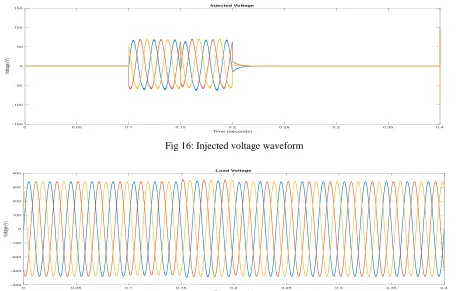
[image:7.612.87.530.489.636.2]Fig 16: Injected voltage waveform
Fig 17: Load voltage waveform of compensated system
8. CONCLUSIONS
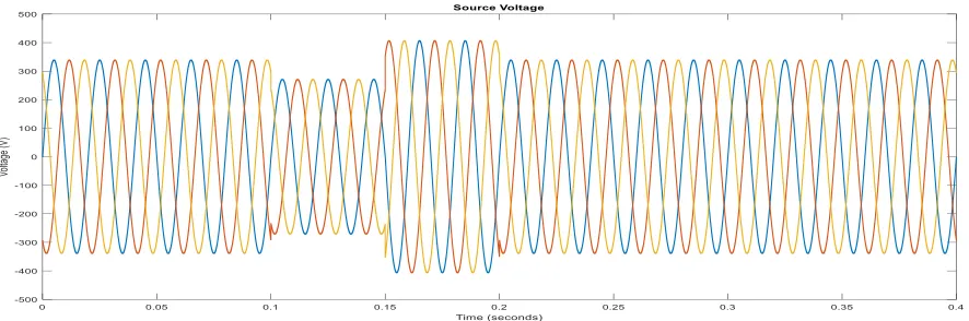
The main contribution of this paper is to sum up different approaches proposed to take care of power quality issues and to provide a comparison between up-to-date approaches using various simulations for combined system. The designed system for compensating sags/swells is working well and has been verified using Simulink. The voltage source inverter was implemented with the help of both SPWM & Bipolar Hysteresis Voltage control. The results were in accordance with theory (SPWM). The designed DVR can compensate any sag of magnitude between 0.1-0.9 pu (in simulation). But in reality a DVR can compensate maximum sag of 0.5 pu.
REFERENCES
[1] M. H. J Bollen, Understanding Power Quality Problems, Voltage Sags and Interruption, Piscataway, NJ: IEEE Press, 1999.
[2] Ezoji, H. Sheikholeslami,A. lessan,S. “Hysteresis Voltage Control of DVR Based on Unipolar PWM” accepted in International Conference on Industrial Technology (IEEE-ICIT09), Australia,2008.
[3] [3] Chellali Benachaiba, Brahim Ferdi, “Voltage Quality Improvement Using DVR,” Electrical
Power Quality and Utilisation, Journal Vol. XIV, No. 1, 2008.