Article
In Vitro Study of a Superhydrophilic Thin Film
Nitinol Endograft that Is Electrostatically
Endothelialized in the Catheter Prior to the
Endovascular Procedure
Mahdis Shayan 1, Yanfei Chen 2, Puneeth Shridhar 2, Colin P. Kealey 3 and Youngjae Chun 1,2,4,*
1 Department of Industrial Engineering, University of Pittsburgh, Pittsburgh, PA 15260, USA; [email protected](M.S.)
2 Department of Bioengineering, University of Pittsburgh, Pittsburgh, PA 15260, USA; [email protected](Y.C.); [email protected] (P.S.)
3 Business Development, NeuroSigma, Inc., Los Angeles, CA 90024, USA; [email protected] (C.K.) 4 McGowan Institute for Regenerative Medicine, Pittsburgh, PA 15219, USA
* Correspondence: [email protected]; Tel.: +1-412-624-1193
Abstract: Electrostatic endothelial cell seeding has evolved as an exceptional technique to improve the efficiency of cell seeding in terms of frequency of attached cells and the amount of cell adhesion for the treatment of vascular diseases. In the recent times, both untreated and superhydrophilic thin film nitinol (TFN) have exhibited strong prospect as substrates for creation of small-diameter endovascular grafts due to their hallmark properties of superelasticity, ultra low-profile character, grown hemocompatible oxide layer with the presence of a uniform endothelial layer on the surface. The purpose of the current study is to understand the effects of endothelial cell seeding parameters (i.e., applied voltage, incubation time, substrate chemistry and cell suspension solution) to investigate the cell seeding phenomenon and to improve the cell adhesion and growth on the TFN surface under electrostatic transplantation. Both parallel plate and cylindrical capacitor models were used along with the Taguchi Design of Experiment (DOE) methods to design in vitro test parameters. A novel in vitro system for cylindrical capacitor model was created using a micro flow pump, micro incubation system, and silicone tubings. The augmented endothelialization on thin film nitinol was developed to determine the effect of cell seeding and deployed in a 6 Fr intravascular catheter setup. Cell viability along with morphology and proliferation of adhered cells were evaluated using fluorescent and scanning electron microscopy. Our results demonstrated that the maximum number of cells attached on STFN in the catheter was observed in 5V with the 2 hr exposure of in the cell culture medium (CCM) solution. The condition showed 5V voltage with 0.68×10⁻⁶ µCelectrostatic charge and 5.11 V·mm-1 electric field. Our findings have first demonstrated that the electrostatic endothelialization on the superhydrophilic thin film nitinol endograft within the catheter prior to the endovascular procedure could enhance the biocompatibility for low-profile endovascular applications.
Keywords: thin film nitinol; electrostatic cell seeding; biocompatibility; endovascular devices
1. Introduction
in luminal diameter [1-3]. One of the examples is bypass surgery, which is the typical treatment used to restore the blood flow in occluded small blood vessels by use of one or more healthy blood conduits. While both arterial and venous allogenic grafts have been used as substitutes for small vascular grafts, the inflammatory reaction and calcification, as well as the limited availability are the major restricting factors for allografts [4] . Occurrence of thrombosis and restenosis result in the failure of vascular grafts in short term such that nearly 25-40% of initially successful of these procedures fail within one year [5].
To address these issues, synthetic materials including expanded polytetrafluoroethylene (e-PTFE) and Polyethylene terephthalate (Dacron©) polyester were recently tested and used to develop vascular grafts in order to overcome the problems. E-PTFE is an inert polymer with an electronegative charged luminal surface (similar to endothelium layer in the native blood vessel) that is antithrombotic and demonstrated successful results for lower limb bypass grafts (7–9 mm). Dacron© polyester has demonstrated an excellent result in large-diameter vascular grafts in thoracic and aortic regions. However, both e-PTFE and Dacron© polyester showed poor patency rates if used for small-caliber vascular grafts [4]. In a randomized trial to compare the e-PTFE with saphenous vein for femoro-popliteal bypass, the patency rate for e-PTFE and saphenous vein is reported 37% and 70% after 54 months, respectively even though both of these showed 92% patency after 1.5 month [4]. Implanted e-PTFE and Dacron© graft do not develop a well-grown confluent endothelialized lumen spontaneously, leading to adhesion of platelets and development of a luminal fibrin layer that can lead to thrombosis. In addition to thrombosis, other causes of vessel narrowing, such as intimal hyperplasia expedite the occlusion. As a result, restenosis results in critical narrowing in 30% to 50% of patients after these synthetic vascular grafts implantation [5]. Recent new studies showed the biocompatibility enhancement for e-PTFE and Dacron© polyester grafts by covering a layer of endothelial cells in a similar structure of the native blood vessel’s luminal surface in order to minimize or to prevent any potential thrombogenic or renarrowing issue [6-8].
conductor comprised of a stainless steel cylinder was placed around the graft such that the internal electrode was placed at the center. Temporary positive electrical charges were induced on the e-PTFE surface as the positive electrically charged electrode and the temporarily negatively charged endothelial cells by the applied voltage were attracted to the surface of e-PTFE. It was found that the optimal electrostatic transplantation conditions are +1 V voltage and 1 6min leading to seeding efficiencies of up to 90% [14]. These results are encouraging and point to significant time savings, however, the fact that ePTFE is a non-conducting material poses, which led difficulties for developing an apparatus due to the non-uniform contact between the metal electrode and non-conducting scaffold materials. If one could use a conducting scaffold covered with a uniform dielectric layer, the production of a positive surface electric charge is achieved by simply connecting it to a positive charge. In addition, typical synthetic polymer grafts are too bulky to be used in small vascular applications, such as neurovascular and coronary artery bypass applications.
Our group has recently recently developed a novel endovascular graft that is covered by a ultra low-profile superhydrophilic thin film nitinol (STFN). While the superhydrophilic thin film nitinol has demonstrated an excellent hemocompatiblity both in vitro and in vivo, there were still concerns about the long-term biocompatibility of this new material. Therefore, we applied the electrostatic endothelialization method on our STFN graft membrane, which contains a grown oxide layer (insulator) on conductive thin film nitinol layer. The oxide layer works as an insulator that generates positive surface charges in a similar way of the synthetic polymer graft. The endothelialization is intended to conduct prior to the endovascular procedure. The aim of the present study is to demonstrate that a superhydrophilic thin film nitinol (STFN) endograft which electrostatically endothelialized in the catheter prior to the procedure represents an endovascular device that is non-thrombogenic and is ideally suited for treating various small vascular diseases.
2. Materials and Methods
2.1. Electric Field Analysis of the Parallel Plate Capacitor Model
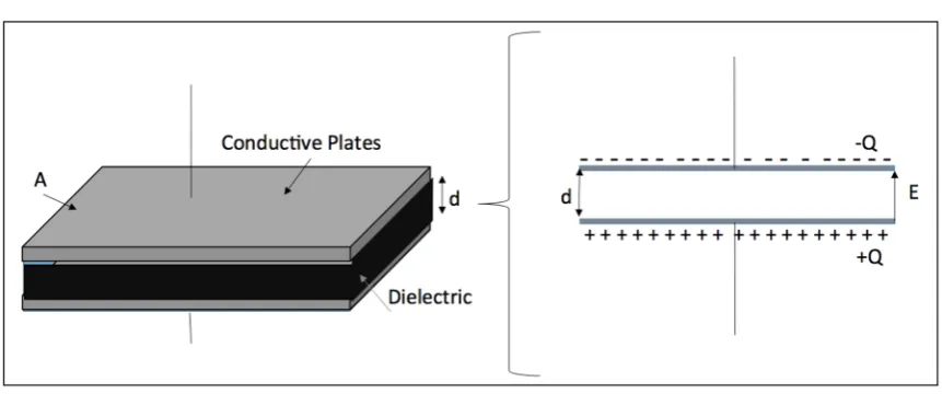
For parallel plate capacitor, the induced electric charge (Q) on the electrode surface and the induced electric field (E) (Figure 1) were calculated using the following Equations:
(1)
(2)
where V is the applied voltage, d is the distance between two electrodes and C is the total capacitance defined by:
(3) where ε0is the permittivity constant (8.85×10⁻¹² F·m-1), A is the surface area of electrodes and k is
the dielectric constant which is around 80 for the cell culture medium [16]. Because no current was recorded during the experiment, the cell culture medium was assumed as dielectric material. We also ignored the capacitance of both the native and newly grown oxide layers due to the minimal thickness of these layers (i.e., nanometer scale) compared with 2 mm distance between two electrodes. The induced electric charge and electric field in each experiment were calculated based on the above Equations.
V
C
Q
=
×
d
V
E
=
Figure 1. The schematic diagram of the induced electric charge (left) and electrical field in a parallel capacitor model (right)
2.2. Electric Field Analysis of the Cylindrical Capacitor Model
For the practical applications the thin film nitinol (TFN) will be placed in the delivery catheter, which has 4-6Fr catheter sizes (i.e., inner diameter of 1.3mm to 2mm). Figure 2 shows a schematic of the deployed TFN for electrostatic cell seeding inside the catheter before the device delivery.
Figure 2. The schematic diagram of the electrostatic cell seeding with thin film nitinol with the
endovascular device delivery catheter
For the cylindrical capacitors composed of an inner cylinder with radius a enclosed by an outer cylinder with radius b (b>a), Gauss’ law was used to evaluate the induced electric field (E) and electric charge (Q) between the electrodes in cylindrical capacitors:
(4)
(5)
=
0
ε
Q
EdA
0
2
π
rL
ε
(6)
(7)
where A is the cylindrical surface with length L and diameter r, V is the electrical potential and C is the capacitance. In our settings, radii a and b was measured as 0.19 mm and 5 mm, respectively and cylindrical surface length L is 8mm.
2.3. In Vitro Cell Seeding Setup
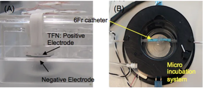
Both untreated TFN (UTFN) and surface-treated TFN (STFN) have been used for the experiment. Briefly, TFN was created by a DC sputter deposition [17]. While the sputtered TFN contains ~10nm thick native oxide layer, thicker insulating layer is important for the electrostatic cell seeding in order to generate surface charged on the insulating layer. Therefore, superhydrophilic surface treatment has been subsequently performed only for the STFN generating approximately 100nm thick titanium oxide layer on TFN with the Hydrogen Peroxide based chemical surface treatment process [18, 19]. Both UTFN and STFN were used as a positive electrode. As can be seen in Figure 3(A) the 3mm x 3mm size TFN was suspended in the cell culture medium working as a positive electrode (cathode). The TFN was placed in the cell culture medium with the distance of 2mm from the bottom negative electrode (anode) in a 24-well tissue culture plate. Similar setup was applied to the cylindrical shape cell seeding experiment. The TFN was deployed inside the endovascular device delivery catheter (here, 6Fr) with the negative electrode, then submerged in the micro incubation system (DH-40iL, Warner Instruments, CT) as shown in Figure 3(B). Both catheter ends were connected to the circulation loop of the cell culture medium. Both temperature and CO2 levels were precisely controlled with the Heater Controller (TC-324C, Warner Instruments, CT) and CO2 Gas/pH Controller (70-2116, Harvard Apparatus, MA). Electric fields were applied using a Laboratory DC Power Supply (GPS-4303, Tecpel Co., Ltd, Taiwan).
Figure 3. The experimental setup for (A) parallel capacitor model and (B) cylindrical catheter based
model.
a
b
Q
Edr
V
b
a
ln
2
0
=
=
πε
a
b
L
k
C
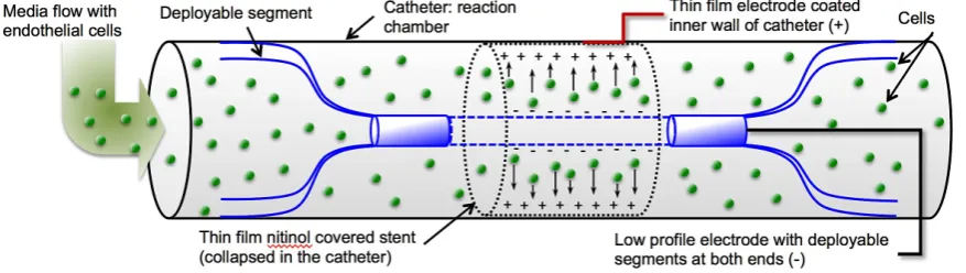
Figure 4 represents the schematic for more details of the cylindrical shape electrostatic cell seeding experimental setup in order to show the mechanism. A TFN sample was deployed in the middle of the 6Fr size catheter, then, a fine nitinol wire (0.014” diameter, Nitinol.com, CA) was placed in the middle of the tube working as a negative electrode (anode). The nitinol wire has two deployable segments, which help positioning this wire accurately in the middle of the tube in order to maintain
Figure 4. A schematic of the cylindrical shape cell seeding experimental setup.
same distance between the TFN and wire. A cell culture media that contains endothelial cells flowed into the catheter and subsequently electric field was applied to the system. The catheter was placed in a micro incubation system in order to maintain the cell culture medium at 37 °C and 5% CO2.
2.4. Design of Experiement (DOE)
To simultaneously evaluate multiple factors which can affect the level of cell seeding and behavior of seeded cells, the Taguchi method was used to design the experiments. The parameters that can potentially affect this EECS process include: the cell suspension solution, the substrate chemistry, applied voltage and the incubation time. The voltage value determines both induced electric field and electrostatic charge. The range of values of these parameters is given in Table 1. For both voltage and time parameters, four levels were selected and for each suspension solution and substrate chemistry parameters, two levels were considered.
Table 1. Electrostatic cell seeding (EECS) parameters and their levels
Level Time (hr) Voltage (V) Suspension solution Substrate
1 0 0.1 PBS UTFN
2 2 1 Cell Culture Medium
(CCM)
STFN
3 6 3
4 24 6
explained above, were performed in 1V, 5V and 15V in cell culture medium. These experiments were done on STFN substrate for 30 min duration and analyzed right after the experiment (i.e., no incubation time). Analysis of variance (ANOVA) technique was utilized to identify the significant factors that affect the number of attached cells.
2.5. Testing the Morphology, Attachment and Viability of Seeded Endothelial Cells
Bovine Aortic Endothelial Cell (Lonza, NJ, USA) were grown in the medium consisting of Endothelial Cell Basal Medium (EBM)-2 (Lonza, NJ, USA) and EGM-2 SingleQuot Kit Suppl. & Growth Factors including (Hydrocortisone 0.02%, FBS 2%, VEGF 0.05%, hFGF-B2%, IGF-1 0.05% and HEGF 0.05%, GA-1000 0.05%) (Lonza, NJ, USA). These cells at passage number 9 at a density of 2×10⁵ cells/cm2 were suspended in the cell culture medium (CCM) or PBS solution. After EECS, the samples were rinsed thoroughly with PBS and stained with Calcein AM (Life Technologies, NY, USA). Three samples in each condition were used and in each sample five spots were randomly picked and the number of attached live cells were counted and used for the analysis (i.e., total of 15 images).
Besides, LIVE/DEAD® cell viability assay (Life Technologies, NY, USA) was done to determine the live attached and dead cells using fluorescent microscopy (Olympus, PA, USA). Both morphology and proliferation of adhered cells were evaluated using SEM after sputtering a thin palladium layer. For SEM imaging, cells were fixed with 2.5% glutaraldehyde (Sigma-Aldrich, MO, USA), dehydrated in a series of ethanol/DI water mixtures including 30%, 50%, 75%, 90% and 100% ratios, then, subjected to drying with hexamethyldisilazane (HMDS) (Alfa Aesar, MA, USA)/ethanol in 3:1, 1:1 and 1:3 volume ratios. The samples were then dried in the chemical hood overnight at room temperature.
2.6. Statistical Analysis
The general linear model (GLM) can be written as:
(8)
where, Y is a matrix with response measurements (i.e., attached number of cells), X is our design matrix (i.e., time duration, voltage, suspension solution and substrate type), B is a matrix of the linear coefficient parameters to be estimated and U is the error matrix and assumed to be uncorrelated and follow a multivariate normal distribution. ANOVA then studies the significance of each predictor variable and R2 statistic estimated the percentage of variation explained by the model.
Standard statistical analysis was conducted using Minitab 16 (Minitab Inc., PA, USA) through calculation of the average factor effect (main effect), analysis of variance (ANOVA) using general linear model and testing the significance of factor’s influence. Using a main effects plot in Minitab examined the differences between level means for one or more factors.
U
XB
3. Results and Discussion
3.1. Electrostatic Endothelial Cell Seeding in Parallel Capacitor-Like Set-up
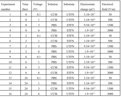
Since there were two 4-level control factors (i.e., time and voltage) and two 2-level control factors (i.e., CCM and substrate), L-16 array was selected without considering the interactions. Experimental plan can be found in Table 2, each row of this table shows an experiment with different combination of the parameter levels. The results of induced surface electrostatic charge in each of Taguchi designed experiments have been calculated based on the Equations (1-3).
Table 2. Experimental plan using L-16 orthogonal array along with induced electrostatic charge
and electrical field in the designed experiments.
Experiment number
Time (hrs)
Voltage (V)
Solution Substrate Electrostatic charge (µC)
Electrical field (V/m)
1 0 0.1 CCM UTFN 3.18×10⁻⁷ 50
2 0 1 CCM UTFN 3.18×10⁻⁶ 500
3 0 3 PBS STFN 9.54×10⁻⁶ 1500
4 0 6 PBS STFN 1.9×10⁻⁵ 3000
5 2 0.1 CCM STFN 3.18×10⁻⁷ 50
6 2 1 CCM STFN 3.18×10⁻⁶ 500
7 2 3 PBS UTFN 9.54×10⁻⁶ 1500
8 2 6 PBS UTFN 1.9×10⁻⁵ 3000
9 6 0.1 PBS UTFN 3.18×10⁻⁷ 50
10 6 1 PBS UTFN 3.18×10⁻⁶ 500
11 6 3 CCM STFN 9.54×10⁻⁶ 1500
12 6 6 CCM STFN 1.9×10⁻⁵ 3000
13 24 0.1 PBS STFN 3.18×10⁻⁷ 50
14 24 1 PBS STFN 3.18×10⁻⁶ 500
15 24 3 CCM UTFN 9.54×10⁻⁶ 1500
16 24 6 CCM UTFN 1.9×10⁻⁵ 3000
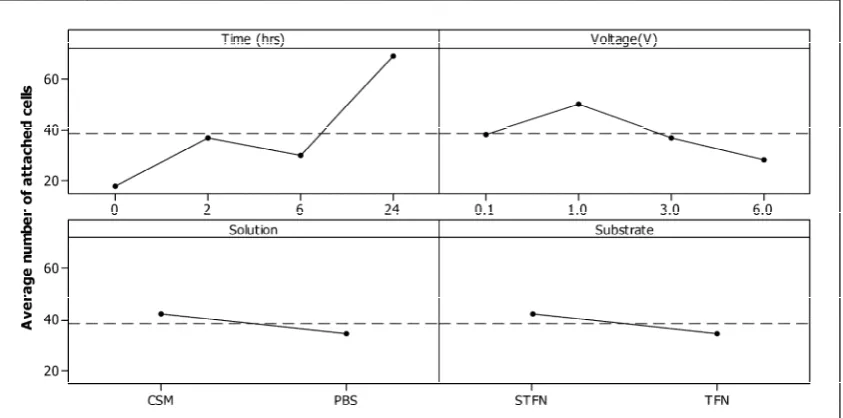
number of attached cells per mm2 slightly increased on STFN (~43) compared to untreated TFN (~35) (Figure 5D). Figure 5 also identified two dominant factors (i.e., time duration and voltage) since these two plots showed relatively higher slopes compared to the variables including suspension solution and substrate type.
Figure 5. Diagram of the average effect: A) time duration, B) voltage, C) cell suspension solution and
D) substrate on the number of attached cells per mm2. The dashed line represents the overall mean of all the levels.
Analysis of variance (ANOVA) technique was performed to identify the significant factors that affect the number of attached cells. Thus, time and voltage with F-ratio of 42.67 (p-value < 0.001) and 7.12 (p-value = 0.016) were respectively identified as the two dominant factors. While solution and substrate parameters had F-ratio of 5.42 (p-value = 0.053) and 5.75 (p-value = 0.048), respectively. The adjusted R-square was 91.05%, suggesting a high correlation between the number of attached cells and predictor variables including time duration, voltage, cell suspension solution and substrate type,
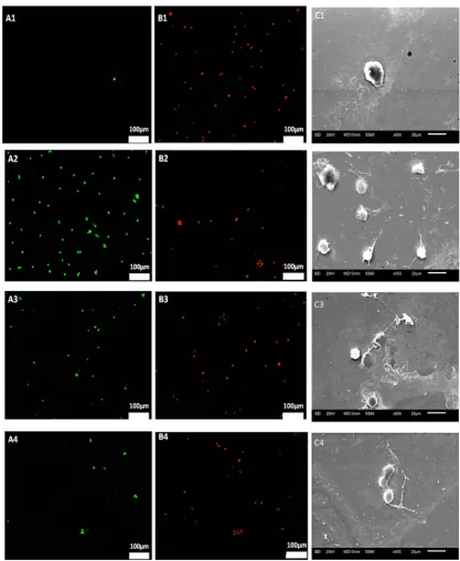
SEM images showed endothelial cells attached on STFN substrate after 2 hrs incubation in the cell medium exhibiting a few nanospikes emerging on the rounded-up cell bodies but upon applying 0.1V, the number and length of these nanospikes significantly increased while under 1V with the same condition, these cells become noticeably flat on the surface (Figure 6).
Figure 6. Representative SEM images of attached endothelial cells on STFN substrate in the cell
The ideal time for endothelialization could be maximum a few hours in the catheter prior to the endovascular procedure. By increasing the incubation time from 2 hrs to 6 hrs, the cell morphology presumably became more flat and the nanospikes emerging on the surface remarkably lengthened. Applying 3V caused cells to become more flat but cell membrane pitting significantly occurred indicating cell damage. By increasing the voltage up to 6V, the level of disintegration and pitting in cell membrane significantly increases. Similar to STFN substrate, the cell membrane damage (i.e., cell membrane disintegration and pitting) under 6V has also been observed in UTFN substrate in both PBS and cell culture medium while no cell membrane damage was observed in UTFN substrate under 3V.
3.2. Electrostatic Endothelial Cell Seeding in Intravascular Catheter
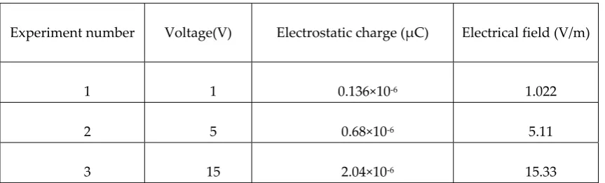
Table 3 represents the value of applied electrical voltage, induced electrical field and the induced electrostatic charge on the STFN substrate placed in the cylindrical capacitor setup of the intravascular catheter. Induced electrostatic charge and electric field was noticeably higher in the parallel capacitor set-up compared to the cylindrical capacitor setup of the intravascular catheter, for instance, under 1V voltage, the induced electric field in parallel capacitor set-up and intravascular catheter set-up was 500 V/m, 1.022 V/m, respectively.
Table 3. Electrostatic cell seeding (EECS) experiments in intravascular catheter.
Experiment number Voltage(V) Electrostatic charge (µC) Electrical field (V/m)
1 1 0.136×10⁻⁶ 1.022
2 5 0.68×10⁻⁶ 5.11
3 15 2.04×10⁻⁶ 15.33
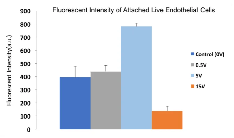
Figure 8. Fluorescent intensity of attached live Calcein AM stained endothelial cells under applying 0V, 0.5V, 5V and 15V conditions.
Cell is the basic structural unit of all living organisms, which contains a watery cytoplasmic solution and surrounded by a cell membrane. One of the important features of biological cells is having electrical nature due to the exchange of electrically charged ions across the cell membrane and showing the electrical potential of its interior relative to the exterior. Cell membranes consist of phospholipid bilayer structure and ion channels (i.e., Kand Cl ion channels) and proteins are embedded across this phospholipid bilayer. Phospholipid bilayer in the cell membrane is an insulator layer that acts as the dielectric separating two electrically conductive regions of the cytoplasm and the extracellular fluid. Therefore, the cell can be modeled by a capacitor. Electric fields exist in many biological systems and influence cell signaling as well as many cellular behaviors and biological events. Therefore, electrophysiological features of cells vary with the surrounding physiological environment. At rest, most cells have typically a potential around -40 to -80 mV indicating that they are dominated by K or Cl permeability. In a study by Jongsma et al., the membrane potential, capacitance and input resistance of isolated human vascular endothelial cells were measured as -16.3±12.7 mV, 53.9±5.5 pF and 2.3±1.3 GΩ [20].
In this study, the effects of four factors (i.e., voltage, substrate, solution, and incubation time) in the parallel EECS setup were studied using Taguchi Design of Experiment (DOE) method. Since parallel capacitor setup is simpler to perform the EECS experiments compared to cylindrical capacitor intravascular setup, it was first used to study the effects of EECS parameters [25]. Design of experiment method allows evaluating multiple factors simultaneously and finding the optimal condition for accelerating and improving the EECS on the various TFN substrates.
Both PBS and cell culture medium (CCM) solutions were used for testing the electrostatic cell seeding effectiveness of TFN materials. While dielectric constants of these two solutions are not significantly different, the main difference between them is the presence of proteins in the cell medium. Our results demonstrated that the average number of attached cells was higher when the cell medium solution was used. Proteins in biological serum effectively play a role in the cell adhesion process such that proteins and biomolecules first adsorb on the surface of materials and then cells attach on these pre-adsorbed proteins. Proteins are large biomolecules and contain multiple functional groups with electrostatic charge; therefore, the electrostatic charge of the substrate can affect the type and the arrangement of the deposited proteins and subsequently impact their function, the ligand binding and cell signaling. The estimation of average effect of voltage showed that increasing voltage up to an optimal range can enhance cell attachment but increasing it beyond this point decreased the number of attached cells.
The applied voltage also affects both the induced electric field and substrate electrostatic charges. McCaig et al., showed electric fields in the range of 75–100 mV·mm−1 with voltage of 1.5– 2.0mV enhanced the elongation and migration of endothelial cells [26], which would be beneficial for better endothelialization. If the applied voltage across the capacitor becomes too large, the dielectric breaks down and results in a short circuit. In addition, high voltage and high electric field can damage the cell membrane. For instance, the number of attached cells was decreased above 15V applied voltage in the cylindrical capacitor test setup compared to the control (0V applied voltage) or the voltage below 15V.
The incubation time did not significantly influence the number of endothelial adhered, however, qualitative evaluation of the adhered cells by SEM images showed that the cells became flatter and lengthened on all TFN materials. The average number of attached cells was slightly higher on the STFN substrate compared to the UTFN.
4. Conclusions
The results demonstrated that the number of attached endothelial cells increased by applying voltage and the detachment did not occur over time. It is also concluded that number of attached cells increased on the STFN substrate and in the cell culture medium solution (i.e., with the presence of serum protein) compared to UTFN substrate and PBS solution, respectively. 1V applied voltage with induced electrostatic charge of 3.18×10⁻⁶ µC and induced electric field of 500 V/m showed the highest endothelial cell attachment in parallel plate capacitor model test.
The condition of 5V voltage with induced electrostatic charge of 0.68×10⁻⁶ µCand induced electric field of 5.11 V/mm-1 (i.e., much lower amount compared to the parallel plate capacitor setup) showed the highest endothelial cell attachment in cylindrical setup with an intravascular catheter. Therefore, the collapsed STFN endograft within the 6 Fr size intravascular catheter can be successfully endothelialized under 5V for 2hrs. In future work, the phenotypic features of attached endothelial cells and the in vivo studies of implanted electrostatic endothelial cell seeded TFN will be evaluated in detail to understand the mechanism for utilization of electrostatic endothelial cell seeding in endovascular device arena.
Acknowledgments: The authors most gratefully appreciate funding provided for this work by Central
Research Development Fund at the University of Pittsburgh
Author Contributions: Mahdis Shayan, Youngjae Chun, and Yanfei Chen have jointly written the paper.
Conflicts of Interest: The authors declare no conflict of interest.
References
1. Bortnick, A.E.; Epps, K.C.; Selzer, F.; Anwaruddin, S.; Marroquin, O.C.; Srinivas, V.; Holper, E.M.; Wilensky, R.L. Five-year follow-up of patients treated for coronary artery disease in the face of an increasing burden of co-morbidity and disease complexity (from the NHLBI Dynamic Registry). The American journal of cardiology, 2014, 113, 573-9. [CrossRef] [PubMed]
2. Criqui, M.H.; Aboyans, V. Epidemiology of peripheral artery disease. Circulation research, 2015, 116, 1509-26. [CrossRef] [PubMed]
3. Behrouz, R.; Malek, A.R; Torbey, M.T. Small vessel cerebrovascular disease: the past, present, and future. Stroke research and treatment, 2012. [CrossRef] [PubMed]
4. Sabik, J.F. Understanding saphenous vein graft patency. Circulation, 2011, 124, 273-5. [CrossRef] [PubMed]
5. Loscalzo, J. Vascular Matrix and Vein Graft Failure Is the Message in the Medium? Circulation, 2000, 101, 221-3. [CrossRef] [PubMed]
6. Stanley, J.C.; Graham, L.M.; Burkel, W.E. Endothelial cell seeded synthetic vascular grafts. Vascular Graft Update: Safety and Performance Philadelphia: ASTM, 1986, 33-43. [CrossRef]
7. Belden, T.; Schmidt, S.; Falkow, L.; Sharp, W. Endothelial cell seeding of small-diameter vascular grafts. ASAIO Journal, 1982, 28, 173-7. [CrossRef] [PubMed]
8. Stanley, J.C.; Burkel, W.E.; Ford, J.W.; Vinter, D.W.; Kahn, R.H.; Whitehouse, W.M.; Graham, L. M. Enhanced patency of small-diameter, externally supported Dacron iliofemoral grafts seeded with endothelial cells. Surgery, 1982, 92, 994-1005. [CrossRef] [PubMed]
9. Herring, M.B.; Dilley, R.; Jersild Jr, R.A.; Boxer, L.; Gardner, A.; Glover, J. Seeding arterial prostheses with vascular endothelium. The nature of the lining. Annals of surgery, 1979, 190, 84. [CrossRef] [PubMed] 10. Seeger, J.M.; Klingman, J. Improved in vivo endothelialization of prosthetic grafts by surface modification
with fibronectin. Journal of vascular surgery, 1988, 8, 476-82. [CrossRef] [PubMed]
11. Zheng, W.; Wang, Z.; Song, L.; Zhao, Q.; Zhang, J.; Li, D.; Wang, S.; Han, J.; Zheng, X.L.; Yang, Z.; Kong, D. Endothelialization and patency of RGD-functionalized vascular grafts in a rabbit carotid artery model. Biomaterials, 2012, 33, 2880-91. [CrossRef] [PubMed]
13. Bowlin, G.L.; Rittgers, S.E. Electrostatic endothelial cell seeding technique for small diameter (< 6 mm) vascular prostheses: feasibility testing. Cell transplantation, 1997, 6, 623-9. [PubMed]
14. Bowlin, G.L.; Rittgers, S.E.; Milsted, A.; Schmidt, S.P. In vitro evaluation of electrostatic endothelial cell transplantation onto 4 mm interior diameter expanded polytetrafluoroethylene grafts. Journal of vascular surgery, 1998, 27, 504-11. [CrossRef] [PubMed]
15. Bowlin, G.L. Apparatus and method for endothelial cell seeding/transfection of intravascular stents. Google Patents; 2000.
16. Sears, F.W.; Zemansky, M.W.; Young, H. University Physics–6th Edition: Addison. Westley Publishing Company, 1982.
17. Ho, K.K.; Carman, G.P. Sputter deposition of NiTi thin film shape memory alloy using a heated target. Thin Solid Films , 2000, 370, 18-29. [CrossRef]
18. Chun, Y.; Levi, D.S.; Mohanchandra, K.; Carman, G.P. Superhydrophilic surface treatment for thin film NiTi vascular applications. Materials Science and Engineering: C ,2009, 29, 2436-41. [CrossRef]
19. Mohanchandra, K.P.; Chun, Y.; Prikhodko, S.V.; Carman, G.P. TEM characterization of super-hydrophilic Ni–Ti thin film. Materials Letters, 2011, 65, 1184-7. [CrossRef]
20. Van Rijen, H.; Van Kempen, M.; Analbers, L.; Rook, M.; Van Ginneken, A.; Gros, D.; Jongsma, H.J. Gap junctions in human umbilical cord endothelial cells contain multiple connexins. American Journal of Physiology-Cell Physiology, 1997, 272, 117-30. [CrossRef] [PubMed]
21. Seuss, S.; Boccaccini, A.R. Electrophoretic deposition of biological macromolecules, drugs, and cells. Biomacromolecules, 2013, 14, 3355-69. [CrossRef] [PubMed]
22. Avgustinik, A.; Vigdergauz, V.; Zhuravlev, G. Electrophoretic deposition of ceramic masses from suspensions and calculation of deposit yields. J Appl Chem(URSS), 1962, 35, 2090-93.
23. Boccaccini, A.; Keim, S.; Ma, R.; Li, Y.; Zhitomirsky, I. Electrophoretic deposition of biomaterials. Journal of The Royal Society Interface, 2010, 7, 581-613. [CrossRef] [PubMed]
24. Besra, L.; Liu, M. A review on fundamentals and applications of electrophoretic deposition (EPD). Progress in materials science, 2007, 52, 1-61. [CrossRef]
25. Rao, R.S.; Kumar, C.G.; Prakasham, R.S.; Hobbs, P.J. The Taguchi methodology as a statistical tool for biotechnological applications: a critical appraisal. Biotechnology journal, 2008, 3, 510-23. [CrossRef] [PubMed]
26. Zhao, M.; Bai, H.; Wang, E.; Forrester, J.V.; McCaig, C.D. Electrical stimulation directly induces pre-angiogenic responses in vascular endothelial cells by signaling through VEGF receptors. Journal of cell science, 2004, 117, 397-405. [CrossRef] [PubMed]