MITIGATION OF VOLTAGE SAG USING
DYNAMIC VOLTAGE RESTORER (DVR)
WITH HYSTERESIS VOLTAGE CONTROL
TECHNIQUE
K.Swaroop Paul Kumar
1, P.Gowthami
2, P.Manjusha Roseline
3PG Student [APS], Dept. of EEE, JNTUK-UCEV, Vizianagaram, Andhra Pradesh, India.1
PG Student [PID], Dept. of EEE, Sri Sai Aditya Institute of Science and Technology, Surampalem, East Godavari,
Andhra Pradesh, India.2
PG Student [PS], Dept. of EEE, Korangi Institute of Engineering and Technology, Korangi, East Godavari, Andhra
Pradesh, India.3
ABSTRACT: In the Power system, maintaining power quality is prominent for a healthy environment between
customer end and generation. Voltage swell, voltage sag or voltage dip, harmonic content are the most frequent terms of power quality problems. These power quality problems distributed power system and effect the customer equipment badly. In order to tackle and mitigate such power quality problems some equipment are used. Such equipment are also called as custom power devices (CPD). Dynamic voltage restorer (DVR) is also commercially called as static series compensator (SSC) is one of the custom power devices. This DVR is a device which enhance the voltage stability in the system. In the sense, it maintains the quality of power by its deliberate action of operation with respective to the voltage sag or voltage swell. Hysteresis voltage control technique is used to operate and control the DVR in this paper.
KEYWORDS: custom power devices (CPD), Dynamic voltage restorer (DVR), hysteresis voltage control technique.
I INTRODUCTION
Today, large usage of sensitive and non-linear loads at the customer end is increasing day by day and hence the power quality is an important aspect that to be considered. Power quality is a set of electrical boundaries that allows a piece of equipment to function in its intended manner without significant loss of performance or life expectancy. Power quality problems like transients (both impulsive transients and oscillatory transients), interruptions, voltage sag, voltage swell, waveform distortion, voltage fluctuations, and frequency variations are frequent in the system [6]. There are two approaches to control the power quality problems. One solution is to done from customer side or from the utility end. This approach is called load conditioning. The other approach is to install the line conditioning system or devices that depress or counter act with the power quality problems. Here the DVR we use is to be placed at the point of common coupling i.e., at the customer side. So that the quality of power that is fed to sensitive equipment increases [1].
In this paper working of DVR for mitigating voltage sag and inducing or boosting the dropped voltage in to the system by DVR using hysteresis voltage control technique is discussed. Among the several control techniques that are used to operate and control the DVR, hysteresis voltage control technique is the most simplest and effective control technique to use. The proposed system is modelled in MATLAB software and the results were discussed about the operation of DVR that helped in improving the quality of power in distribution system.
II FACTS DEVICES AND CUSTOM POWER DEVICES (CPD)
transfer capability.” Static Synchronous Series Compensator (SSSC), Interline Power Flow Controller (IPFC), Unified Power Flow Controller (UPFC), Thyristor Controlled Phase Shifting Transformer (TCPST,)Thyristor Controlled Series Capacitor (TCSC), Thyristor Switched Series Reactor (TSSR), Thyristor Switched Series Capacitor (TSSC), Thyristor Controlled Series Reactor (TCSR),Static Synchronous Compensator (STATCOM), Static Synchronous Generator (SSG), Static Var Compensator (SVC), Thyristor Controlled Reactor (TCR), Thyristor Switched Reactor (TSR), Thyristor Switched Capacitor (TSC), Static Var Generator (SVG) are some FACTS devices.
Custom power devices (CPD) are the devices which customise the power to improve the power quality accordingly. Distribution Statcom (D-STATCOM), Dynamic Voltage Restorer (DVR), Unified power quality conditioner (UPQC), Active Power Filters, Surge Arresters (SA), Uninterruptible Power Supplies (UPS), Solid State Fault Current Limiter (SSFCL), and Solid-State Transfer Switches (SSTS) are some custom power devices. These are either connected in series or in parallel or in combination of both connections [5].
III DYNAMIC VOLTAGE RESTORER (DVR)
A DVR is a system or device composed of a voltage source converter (VSC), DC power bank or a battery system and a booster or injection transformer connected with the distribution line in series and induces or compensates for the voltage disturbances on the distribution bus bar [11]-[21]. From the Fig 1, we can clearly pictures the DVR in a distribution system [3].
Fig 1: A dynamic voltage restorer (DVR) in a distribution system
IV WORKING PRINCIPLE OF DVR
The supply voltage is VS and load voltage is VL, dynamically controlled voltage VDVR is generated by the forced
commutation of converter which is in series with the line voltage by the booster transformer. The control system is nothing, but a hysteresis voltage control model which operates and controls the VSC with the triggering pulses. The harmonic contents are decreased by the filters [7],[9].
From the above fig.2 it is clear that the DVR consists of a VSC for generation of Voltage, a control system to control the DVR with the triggering pulses, filter for harmonics reduction and a Transformer which is connected in series with the system.
V OPERATING MODES OF A DVR
In general DVR has two modes of operations. They are standby mode and boost mode. In the standby mode VDVR is
zero. The booster transformer does not inject voltage in to the line. As there is no sag condition in the line. Most of the time DVR will be in this standby mode only. In the boost mode, VDVR is greater than zero. When there is a detection of
sag in supply voltage, DVR comes in to operation dynamically and boosts up the drop voltage in to the line [2].
VI HYSTERESIS VOLTAGE CONTROL TECHNIQUE
Initially to workout with this hysteresis voltage control technique, a voltage detection method is to be considered. In general different voltage detection methods are used to detect the initial forming and end of the voltage sag and/ or the associated dip depth and the phase shift. Some of the methods are [4]-[8]:
a. Monitoring peak values of supply voltage. b. Phase locked-loop (PLL) for each phase. c. Monitoring of Vd in a vector controller.
d. Fourier Transform (standard but slow process). e. Wavelet Transformer method to each phase.
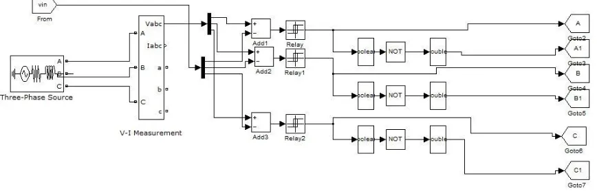
Phase locked loop method is associated with the hysteresis voltage control technique. Figure3 gives the Simulink representation of hysteresis voltage control technique and generating of the triggering pulses that area used to operate and control the voltage source converter (VSC) [9].
VII TEST SYSTEM
A test system is modelled for DVR implementation. The system data is as follows: 415 V, base value 25KVA, feeder length 5 km, 23.8 KVA load, System frequency 50 Hz, feeder impedance 0.05+j0.3 PU, load impedances: 2.0+j1.5 PU (phase-a), 2.5+j2.0 PU (phase-b), 1.0+j2.5 PU (phase-c), desired load voltage 1.0 PU [10].
Fig 3: Hysteresis voltage controller model
The fig.3 represents the Hysteresis voltage control technique model which is used to generate the triggering pulses for the switching devices in the Voltage Source Converter (VSC). The fig.4 represents the Simulink model of a system
Fig 4: Simulink model of a system with DVR
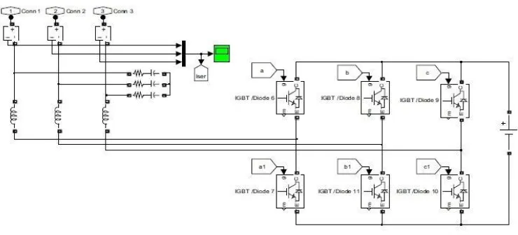
The below fig.5 represents the Voltage Source Converter (VSC) that is an integral part of DVR to produce the required amount of voltage and induces in to the system line accordingly with the help of series transformers.
Fig 5: Simulink model of a voltage source converter (VSC) in DVR
The voltage thus obtained contains harmonics which are eliminated by filters and this VSC can be also used to mitigate Voltage Swell.
VIII RESULTS
Fig 5: Voltage Response (Voltage sag) of system during fault occurrence.
Here in the above given fig.5 the Voltage sag occurred at a period from 0.2 seconds to 0.5 seconds due to occurrence of fault in the system.
Fig 6: Voltage Response at the load (after DVR voltage injection
When in the presence of DVR, it injects the voltage that is required in order to make the reliable and continuous Voltage profile in the system there by making the system with supply of quality power.
IX CONCLUSION
The proposed model of Dynamic voltage restorer (DVR) which is controlled and operated by hysteresis voltage control technique is modelled using MATLAB Simulink. This paper explains a better solution for mitigating the power quality problems since these problems will have an ultimate impact on the customer sensitive equipment. For fast switching frequency MOSFET can be used instead of IGBT. Form the family of custom power devices, this dynamic voltage restorer with hysteresis voltage control shows the better results in mitigating the voltage sag, and even voltage swell, harmonics.
REFERENCES
[1] C. Sankaran, "Power quality," (CRC Press, New York, 2001)
[2] Benachaiba Chellali, FERDI Brahim, “Voltage Quality Improvement Using DVR,” Electrical Power Quality and Utilizations, Journal Vol. XIV, No. 1, 2008
[3] H. Hingorani “Introducing custom power” IEEE spectrum, vol.32 no.6 June 1995 p 41- 48.
[4] C. Fitzer, M. Barnes and P. Green, “Voltage Sag Detection Technique for a Dynamic Voltage Restorer”, IEEE Trans. Industry Applications Vol. 40(1), Jan. 2004, pp. 203 - 212.
[5] H. Hingorani “Introducing custom power” IEEE spectrum, vol.32 no.6 June 1995 p 41- 48.
[6] M. Bollen. “Understanding Power Quality Problems, voltage sags and Interruptions.” IEEE press, 1999.
[7] Understanding of Dynamic Voltage Restorers Through MATLAB Simulation. Thammasat Int. J. Sc. Tech. Vol. 11,N o. 3, July-September 2006 [8] Hysteresis Voltage Control Technique in DVR fed Induction Motor Drive. ISSN No: 2348-4845 International Journal & Magazine of
Engineering Technology, Management and Research.
[9] Dynamic voltage restorer for compensation of voltage sag and swell. ISSN: 2231-1963. International Journal of Advances in Engineering & Technology, July 2012.
[10] Arindam Ghosh, Avinash Joshi “Design of a Capacitor-Supported Dynamic Voltage Restorer (DVR) for Unbalanced and Distorted Loads” IEEE Transactions on Power Delivery, Vol. 19, No. 1, January 2004.
[11] Fawzi AL Jowder “Modeling and Simulation of Dynamic Voltage Restorer (DVR) Based on Hysteresis Voltage Control” The 33rd Annual Conference of the IEEE Industrial Electronics Society (IECON) Nov. 5-8, 2007.
[12] N. H. Woodley, L. Morgan. , and A. Sundaram, "Expenience With An Inverter Based Dynamic Voltage Restorer,," IEEE Tranis. Power Delivery, vol.14, No. 3 pp. 549-557, July 1999.
[14] J.G Nielsen and F. Balaabjerg," Comparison system topologies for dynamic voltage restorer," in Proc. IEEE/IASO] Conf., 2001, pp. 2397-2403.
[15] John Godsk Nielsen, Frede Blaabjerg and Ned Mohan," Control Strategies for Dynamic Voltage Restorer Compensating Voltage Sags with Phase Jump."in Proc. IEEE 16th AppI. Power Electron. Conf. Expo., Anaheim, C.A, 2001,pp. 1267-1273.
[16] Changjiang Zhan, Vigna Kumaran Ramachadaramurthy, Atputharajah Arulampalam, Chris Fitzer, Stylianos Kromlidis, Mike Barns and Nicholas Jenkins, "Dynamic Voltage Restorer Based on Voltage-Space Vector PWM Control," ," IEEE Trans. Induistrial Applications, vol. 37, No.6 pp. 1855-1863, November/December 2001.
[17] Anindam Ghosh, Amit Kumar Jindal and Avinash Joshi. "Design of a Capacitor-Supported Dynamic Voltage Restorer (DVR) for Unbalanced and Distorted Loads," IEEE Trans. Power Delivery, vol. 19, No.1 pp. 405-413, January 2004.
[18] Poh Chiang, D Mahinda Vilathgamuwa, Seng Khai Tang and Hian Lih Long, "Multilevel Dynamic Voltage Restorer," IEEE Trans. Power Electronics Letters, vol. 2, No.4 pp. 125-130, December 2004.
[19] D. D Solin, T. E. Grebe, M. F. Granaghan and A. Sundarm," Statistical Analysis of Voltage DIP's and Interruption-Final results from the EPRI distribution system power quality monitoring survey.," in Proc. CIRED'99,ch.2 1999.
[20] Chnis Fitzer, Mike Barns and Peter Green, "Voltage Sag Detection Technique for a Dynamic Voltage Restorer," IEEE Trans. Power Delivery, vol. 40, No.1 pp. 203-212, January/February 2004.