ABSTRACT
This paper proposes a short current control method to eliminate the short current by regulating the switching frequency to approach the inherent frequency. When system running in force resonant mode, there will exist dangerous short current between the resonant network and the switching network when switching frequency drifts away from inherent frequency of the resonant network. A novel frequency tracking method based on short current detection is proposed for IPT applications. In addition, an instantaneous short current detection method utilizing cheap comparator is proposed. Furthermore, a fast and accurate tracking method is proposed to calculate the frequency mismatch and make a correction. The method can realize accurate frequency correction in several oscillation periods.
Keywords- Electromagnetic coupling, frequency control, inductive power transfer (IPT).
I. INTRODUCTION
Inductive power transfer (IPT) technology realizes efficient energy transfer across large air gap from power supply to electrical equipment. With its rapid development, more and more applications have been emerging in recent years such as mobile phone, electrical vehicle material handling, and biomedical implants. For a typical IPT system, resonant tanks are very commonly used to produce low-distortion sinusoidal oscillation and increase the system reactive capability. However, the inherent parameters of the resonant tanks may dynamically drift away from the designed parameters due to load variation and mutual coefficient change. It is because the mutual coupling between the primary and secondary sides will produce dynamical reflection impedance in the primary resonant tank and cause its inherent frequency drifting. In order to realize soft switching, the topology switching signal must keep up with the inherent frequency variation. It should be noted here that the inherent frequency refers to the inherent soft switching frequency of the primary inverter, which transforms dc input to high-frequency ac output. Typical frequency tracking method is a passive tracking method, which completes topology switching by detecting the zero crossing points of resonant variables. This method is efficient to produce a self-sustained oscillation. However, it normally requires start-up control to produce initial oscillation, and the oscillation may fail in the low-quality-factor condition. Most important of all, this method cannot realize accurate frequency tracking. There inevitably exists a short-time lag in the topology switching due to the time delay and disturbance on gate driver and detection circuit in the feedback loop. The switching time lag will result in resonant waveform distortion and augment of switching loss. In particular, according
to the first wireless power standard “Qi” the oscillation frequency in commercial IPT product should be set in the frequency range from 110 to 205 kHz. In the high-frequency range, the system becomes more complex and sensitive because many parasite parameters will affect system performance. A tiny time delay or disturbance in the feedback path may cause the system performance to fall drastically. However, due to the inherently passive running property, it is impossible to eliminate the switching time lag and disturbance so that the frequency tracking error will always exist. Compared with the passive tracking method, an active tracking method which completes topology switching by external switching signal is seen to be a good alternate to solve these problems. However, it is greatly relied on the tracking accuracy and speed. Since the inherent frequency is determined by an implicit high-order differential equation set, it is difficult to obtain its accurate value. Furthermore, even if the inherent frequency can be calculated, the time consuming will be unaffordable for real-time tracking. Therefore, instead of the complex calculation, a simple and real-time tracking method with unknown inherent frequency is needed. In the IPT system, its well known that the short current is adverse which should be avoided. The short current occurs when resonant tank is shorted by the switching network. It is caused by mismatch between the driving frequency and the inherent soft switching frequency of the resonant tank. A large mismatch can produce dangerous high current which may cause the switching devices to fail. It has been found that the short current occurs almost instantaneously while the mismatch appears. Therefore, it can be utilized as a fast and accurate ruler to measure the frequency error.
II. OBJECTIVE
A tiny time delay or disturbance in the feedback path may cause the system performance to fall drastically. However, due to the inherently passive running property, it is impossible to eliminate the switching time lag and disturbance so that the frequency tracking error will always exist. Compared with the passive tracking method, an active tracking method which completes topology switching by external switching signal is seen to be a good alternate to solve these problems.In the IPT system, its well known that the short current is adverse which should be avoided. The short current occurs when resonant tank is shorted by the switching network. It is caused by mismatch between the driving frequency and the inherent soft switching frequency of the resonant tank. A large mismatch can produce dangerous high current which may cause the switching devices to fail. It has been found that the short current occurs almost instantaneously while the mismatch appears. Therefore, it can be utilized as a fast and accurate ruler to measure the frequency error.
PREETI V. HAZARE Prof. R. Babu
Vivekananda Institute of Technology and Vivekananda Institute of Technology
Science, Karimnagar and Science, Karimnagar
III. SINGLE-PHASE TRANSFORMERS
Transformers are made up from primary and secondary coils (called windings) that are made from turns of insulated wire. The coils are arranged on a core of magnetic material that increases the amount of magnetic flux set up by one coil and will make sure that most of it links with the other coil; in this way mutual inductance is increased. A simple transformer is illustrated in figure 1 a) and the corresponding circuit diagram is shown in figure 1 b). The primary winding has a voltage of U1 across it and is made of N1 turns of wire. The secondary coil has a voltage of U2 across it and is made from N2 turns. An alternating current in the primary coil will set up an alternating magnetic flux in the core and the primary's self inductance induces an EMF which opposes the supply voltage that is driving the current. The induced EMF will almost be the same magnitude as the supply voltage and although there will be a small difference, this is normally ignored. The changing EMF from the primary coil links with the second coil and mutual inductance causes an EMF to be induced. It is normally assumed that all of the flux from the primary links with the secondary, and although this is not strictly true it is a good approximation and the induced EMF per turn in the primary is taken to be the same as the induced EMF per turn in the Secondary
Fig1 (a) simple transformer; (b) the circuit diagram for a simple transformer
III. SHORT CURRENT PRINCIPLE
In terms of structures of resonant network at primary side, there are normally two types. One is parallel resonant, and the other is series resonant. The short current typically appears in parallel resonant structure. A typical parallel-resonant-type ICPT system is shown in Fig. 2. As can be shown, the inductively coupled power transfer (ICPT) system can be divided by primary and secondary sides. At the primary side, the dc input Edc and filter compose a quasi current source. In addition, the switching network consists of two switch pairs (S1, S4) and (S2, S3) and their inherent inverse parallel diodes (SD1–SD4).The two switch pairs operate complementarily at the forced switching frequency, transform dc current input to high-frequency square-wave current, and inject it into the resonant network, which is composed of resonant inductor LP , capacitor CP , and equivalent series resistance (ESR) resistance RLP . The resonant network converts the square-wave current to sinusoidal current for primary coil to produce alternating magnetic field. At the secondary side, the secondary coil will pick up energy from the magnetic field and produce resonance in the parallel resonant network composed of resonant inductor LS and capacitor CS. With the rectifier and filter network (Lf, Cf ), ac energy is transformed to dc output to the load (RL). Secondary coil will pick up energy from the magnetic field
and produce resonance in the parallel resonant network composed of resonant inductor LS and capacitor CS. With the rectifier and filter network (Lf, Cf ), ac energy is transformed to dc output to the load (RL).
IV. OPERATION OF SWITCHES A. Higher Case
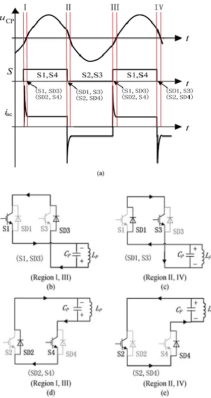
The higher case can be illustrated in Fig. 3. As it can be seen from 3(a), the waveforms from up to down are resonant capacitor voltage uCP, switching signal S, and the input current of
the resonant tank, respectively. For the switching frequency is higher than the inherent frequency, the switching instants will appear before the zero switching points of uCP. In addition, the
mismatches will produce four short current regions (Region I–IV). In each region, the short current has different path and can be illustrated from 3(b) to 3(e), respectively. In Regions I and III, the switch pair (S1, S4) turns on and the switch pair (S2, S3) turns off. However, as the resonant voltage uCP is below zero, two short
current loops will form in the inverter bridge. The one shown in 3(b) is the upper short current loop including S1 and SD3. The other shown in 3(d) is the lower loop include SD2 and S4. In Regions II and IV, the switch pair (S1,S4) turn on and (S2, S3) turn off. However, the resonant voltage uCP is above zero.
Similarly, there are two short current loops. The one shown in 3(c) is the upper one including SD1 and S3, and the other shown in 3(e) is the lower one including S2 and SD4. As the total resistance in the short current path is approaching zero, the short current can be very large and result in the sharp peak of input current Iac shown in
Fig 3: Switching frequency higher case. (a) Operating waveforms when short current occurs. (b) (Regions I and III) Upper short current loop. (c) (Regions II and IV) Upper short current loop. (d) (Regions I and III) Lower short current loop. (e) (Regions II and IV) Lower short current loop.
B. Lower Case
When the switching frequency is lower than inherent frequency, the short current will appear as well. However, it is different from the higher case in nature. The lower case can be illustrated in Fig. 4. As it can be seen from 4(a), since the switching frequency is lower than the inherent frequency, the switching instants will lag behind the zero crossing points of uCP.
Furthermore, the mismatches will produce four short current regions (Regions I–IV). In Regions I and III, when the resonant voltage uCP crossing the zero, the switching pair (S2, S3) still
maintains ON STATE because the switching signal is lagged behind. Two short current loops will form in the upper and lower bridges, respectively. The one including SD1 and S3 is shown in 4(b), and the other including S2 and SD4 is shown in 4(d). In Regions II and IV, the switch pair (S1, S4) will maintain ON
STATE. Similarly, the upper short current loop including S1 and SD3 is shown in 4(c), and the lower one including SD2 and S4 is shown in 4(e). However, it should be noted that the short current is driven by resonant inductor LP instead of capacitor CP as the resonant voltage is clamped to zero. Therefore, the short current peak of input current iac shown in (a) is much lower than that of the higher case. In addition, in higher case, the short current appears at the front end of the switching signal, while in the lower case, it appears at the back end.
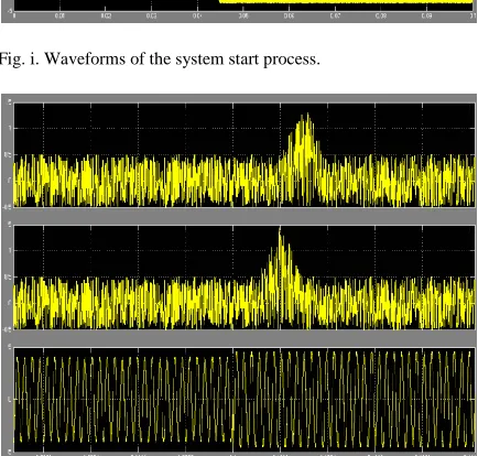
V. SIMULATION WAVEFORMS
Fig. i. Waveforms of the system start process.
Fig. ii. Waveforms of load change from R2 to R1 (from light to heavy load conditions).
Fig. iii. Waveforms of load change from R1 to R2 (from heavy to light load conditions).
VI. CONCLUSIONS
In this paper, a novel accurate frequency tracking method based on short current detection has been proposed for an IPT system. An instantaneous short current detection method utilizing cheap comparator is proposed. Furthermore, a fast and accurate method is proposed to calculate the frequency mismatch and make a correction. Compared with the conventional autonomous oscillation method, this method is an active one which can overcome the common problems such as feedback delay, resonant failure, and additional start-up circuit. Furthermore, the tracking strategy is simple and economic for hardware implementation. It is particularly useful for realizing soft switching in high-frequency IPT applications.
REFERENCES
[1] Xin Dai, Member, IEEE, and Yue Sun “An Accurate Frequency Tracking Method Based on Short Current Detection for Inductive Power Transfer System”. IEEE TRANSACTIONS ON INDUSTRIAL ELECTRONICS, VOL. 61, NO. 2, FEBRUARY 2014
[2] M. Budhia, J. T. Boys, G. A. Covic, and H. Chang-Yu, “Development of a single-sided flux magnetic coupler for electric vehicle IPT charging systems,” IEEE Trans. Ind. Electron., vol. 60, no. 1, pp. 318–328, Jan. 2013.
[3] M. Drader, “Shared coil for inductive charging and hearing-aidcompliance requirements in mobile phones,” European Patent 2 450 840 A1, May 9, 2012
[4] S. Hasanzadeh, S. Vaez-Zadeh, and A. H. Isfahani, “Optimization of a contactless power transfer system for electric vehicles,”IEEE Trans. Veh. Technol., vol. 61, no. 8, pp. 3566– 3573, Oct. 2012.
[5] J. U. W. Hsu, A. P. Hu, and A. Swain, “Fuzzy logic-based directional fullrange tuning control of wireless power pickups,” IET Power Electron., vol. 5, no. 6, pp. 773–781, Jul. 2012.
[6] B. Sharp and H. Wu, “Asymmetrical voltage-cancellation control for LCL resonant converters in inductive power transfer systems,” inProc. IEEEAppl. Power Electron. Conf. Expo., Orlando, FL, USA, Feb. 5–9, 2012, pp. 661–666.
[7] Y. L. Ho, D. M. Budgett, and A. P. Hu, “Minimizing power loss in aircored coils for TET heart pump systems,”IEEE J. Emerg. Sel. Topic Circuits Syst., vol. 1, no. 3, pp. 412–419, Sep. 2011.
[8] A. K. RamRakhyani, S. Mirabbasi, and M. Chiao, “Design and optimization of resonance-based efficient wireless power delivery systems for biomedical implants,”IEEE Trans. Biomed. Circuits Syst., vol. 5, no. 1, pp. 48–63, Feb. 2011