Broadband Circularly Polarized Slotted Patch Antenna Loaded
with Short Pins
Xiangdong An*, Jianjun Wu, and Yingzeng Yin
Abstract—In this letter, a design for broadband circularly slotted patch antenna fabricated on a single-layered printed circuit board (PCB) with unidirectional radiation is described. It is fed by a simple center-fed feeding scheme. Unlike conventional slotted patch antennas, the proposed antenna is loaded with four short pins such that both matching and axial-ratio (AR) bandwidths are improved. In addition to realize the CP radiation at higher frequencies, a cross-slot with different arm lengths, which is cut from the center-fed patch is used. Then, the proposed antenna operates as magnetic dipoles to generate circular polarization at low frequencies after four short pins are added to connect the patch to the ground. Thus, by combining the two modes, bandwidths of 30.2% (1.83–2.48 GHz) for |S11|<−10 dB
and 21.2% (1.98–2.45 GHz) for axial ratio (AR) < 3 dB around the center frequency of 2.15 GHz are measured. Moreover, stable gain of over 8 dBic and good radiation patterns are also observed across the operating band.
1. INTRODUCTION
Circularly polarized (CP) antennas have attracted much attention in wireless communication systems, such as global positioning system (GPS) [1], radio frequency identification (RFID) [2], satellite communication [3], and wireless local area networks (WLANs) [4], for the reason that they can provide flexible orientations between the transmitter and receiver. CP antenna designs of various forms have been reported in literatures, such as virtually shorted patch [5], slotted patch [6] and magneto-electric dipole [7]. By utilizing four symmetrical parasitic shorting strips [5], the antenna size is reduced and the broadside radiation patterns are retained. In [6], CP performance is achieved by cutting cross slots with different lengths. And the axial ratio (AR) bandwidth is further broadened by optimizing the width and position of the cross slot. The antenna in [7] was formed by dipoles and two trapezoidal-shaped magnetic dipoles. The advantages of this design include wide operating bandwidth and symmetrical radiation patterns. But an extra feeding network of power division and phase delay is required. In [8], by grounding the four sides of the slotted patch with metal sheets, the shorted bow-ties together with the ground act as two orthogonal magnetic dipoles to yield CP wave.
In addition, radiation performances are issues that cannot be neglected in antenna designs. In [9], the balance-like center-slot-feeding structure was proposed to reduce cross-polarization levels and improve symmetrical co-polarized radiation patterns. Here, we employ the simple center-fed structure in CP antenna design. In order to broaden the bandwidth of the original slotted-patch antenna, four short pins are added to the patch edges to make the antenna operate as magnetic dipoles at lower frequencies.
In this letter, we propose a new cross-slot CP antenna. Unlike the conventional cross-slot antennas, the proposed antenna is designed with four short pins such that both impedance and AR bandwidths
Received 24 May 2016, Accepted 14 September 2016, Scheduled 21 September 2016
* Corresponding author: Xiangdong An ([email protected]).
are enhanced. Details of designs and results of the proposed antenna are shown. A study of the antenna characteristics is presented by simulations and experiments.
2. ANTENNA DESIGN AND PARAMETER DISCUSSION
The proposed antenna is simulated with the aid of ANSYS high-frequency structure simulator (HFSS 15) software. The geometry of the proposed antenna is shown in Figure 1, which is composed of a slotted patch on the bottom of 61×61 mm2 FR4 substrate with a thickness of 1 mm, feeding strips on the two sides of 20×20 mm2 FR4 substrate with the same thickness as the former, 120×120 mm2 ground plane and four short pins with radius of 0.65 mm. The FR4 substrates have relative permittivity of 4.4 and loss tangent of 0.02. As illustrated in Figure 1, two orthogonal slots with lengths ofL1 and
L2 are placed on the diagonal of a square patch. Then the patch is separated into four parts A, B, C
and D, as shown in Figure 1. The patch is fed by two parallel strips with the wider strip connected to part B and the narrower strip connected to part D. In order to form an electrically balanced and structurally symmetrical feed, the width ratio (Wf1/Wf2) of two parallel strips is chosen to be some
value between 1 : 1 and 1 : 2 according to the empirical parameters in Reference [9]. Furthermore, the wider feed strip is jointed to the ground directly and the narrower strip is welded to the inner core of the SMA port, as shown in Figure 1 and Figure 2.
The cross-slot is widely used in exciting CP wave, it is used to generate a dual-frequency dual-sense CP antenna in [10]. In [11], compact CP antenna is excited by cross-slot and peripheral cuts. In this letter, circular polarization of two operation scheme is mainly generated by the cross-slot. The proposed antenna is firstly designed without short pins to operate around 2.4 GHz. Circular polarization is realized by the cross-slot with different slot lengths. The simulated |S11| and AR of the antenna without short
pins for different lengths (L1 and L2) are shown in Figure 3. All parameters are kept constant except
L1 andL2, as shown in Figure 3,L1 andL2 have significant influence on both AR and|S11|. The reason
for this result is that the lengths of the cross-slot would affect the resonant frequency and axial ratio of the antenna. WhenL1 = 59 mm (0.58λ) andL2 = 43 mm (0.42λ), where λ is the slot-line wavelength
referring to 2.4 GHz, the optimal results are obtained in terms of both impedance and AR band widths. Since the currents in the antenna without short pins concentrate around the slot at 2.4 GHz, the slot-mode is slightly affected by the introduction of short pins. Then, four short pins which connect the patch to ground are located at the center of the patch edges. At low frequencies, the patch, short pins and ground work together to form different circuits at different time slots. And these circuits are
equivalent to magnetic dipoles. At t = 0, current on the circuit contained the two short pins located at x-axis forms magnetic dipoles along the y-axis. At t = T1/4, current on the circuit contained the
two short pins located at y-axis forms magnetic dipoles along the x-axis. The asymmetric cross slot also provides 90◦ phase difference for the two magnetic dipoles to generate circular polarization at lower frequencies. By combining the slot mode and the magnetic-dipole mode, wide CP bandwidth is obtained consequently. With the same parameters (Dimensions are L= 61, L1 = 59, L2 = 43, Ws = 2, Wf1 =
0.5, Wf2 = 1 and H= 20. (unit: millimeters)), the comparison on AR between the proposed antenna
and the antenna without short pins is shown in Figure 4. Figure 4 shows that both the proposed antenna and the antenna without short pins have a good CP performance around 2.4 GHz. It can be concluded
Figure 3. Simulated|S11|and AR of the antenna without four short pins.
Figure 4. Simulated AR of the proposed antenna and the antenna without short pins.
(a)
(b)
Figure 6. Simulated|S11|and AR of the proposed antenna for different W s.
Figure 7. Simulated|S11|and AR of the proposed antenna for different L.
that the second minimum AR point of the proposed antenna is mainly determined by the cross slot on the patch. The first minimum AR point is introduced by the magnetic-dipole mode when short pins are inserted. To further investigate the antenna operating mechanism, the currents on the antenna at different times (t= 0 and t =T1/4, t= 0 and t =T2/4) are shown in Figure 5, where T1 and T2 are
the period of oscillation at 2.04 GHz and 2.34 GHz.
The simulated |S11| and AR of the antenna for different widths (W s) and different Lengths (L)
are shown in Figures 6–7. Figure 6 illustrates the simulated |S11|and AR of the antenna for different
widths (W s) of the cross-slot. AsWs varies from 1.5 to 3 mm with an increment of 0.5 mm and the other parameters kept constant, the first minimum of |S11| and AR point are slightly changed. While the
different slot widths (W s) have a considerable influence on the second minimum of|S11|and AR point.
The reason for this phenomenon is that the second minimum of |S11| and AR point of the proposed
antenna are mainly determined by the cross-slot mode, which is determined by the dimensions of the cross-slot. And whenWs = 2 mm, the optimal results are obtained. Moreover, asL varies from 57 mm to 63 mm with an increment of 2 mm and the other parameters kept constant, it can be seen from Figure 7, the length (L) mainly affects the first minimum of|S11|and AR. Obviously, as the length (L)
increases, the first minimum of |S11|and AR shift to a lower frequency. However, the second minimum
of |S11| and AR point are influenced slightly. The reason for this result is that the first minimum of
|S11| and AR point is introduced by the magnetic-dipole mode, which is affected by the length of the
3. MEASURE RESULTS
An antenna prototype has been fabricated and measured by Agilent N5062A Vector Network Analyzer. The photograph of the antenna is shown in Figure 2. The radiation performances are measured in an anechoic chamber with SATIMO system. Figure 8 shows the simulated and measured |S11|of the
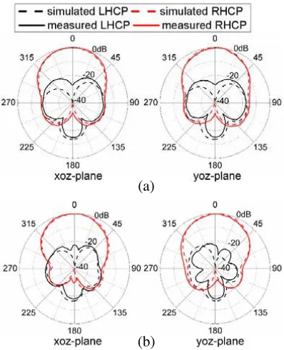
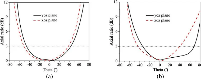
proposed antenna. The simulated and measured normalized radiation patterns at 2.04 and 2.34 GHz are displayed in Figure 9. It is observed that the proposed antenna has symmetrical right-hand circular polarization (RHCP) radiation patterns due to the center-feed structure. The 3-dB AR beamwidth is over 90◦ in both planes for the lower and higher frequencies, as shown in Figure 11.
The measured bandwidth for |S11| <−10 dB is 30.2% from 1.83 to 2.48 GHz, which has a small
deviation compared to simulated results due to fabrication errors. Moreover, the antenna exhibits stable gain of about 8.5 dBic along +z-axis direction over the effective 3-dB AR band from 1.98 to 2.45 GHz (21.2%), as shown in Figure 10.
Figure 8. Simulated and measured|S11|of proposed antenna.
(a)
(b)
Figure 10. Simulated and measured gain and AR of proposed antenna.
(a) (b)
Figure 11. Simulated AR versus theta angle at (a) 2.04 GHz and (b) 2.34 GHz.
4. CONCLUSION
A wideband CP slotted patch antenna is proposed in this letter. The proposed antenna is simply center-fed and loaded with four short pins. The center-center-fed structure is adopted to obtain wide bandwidth and symmetrical and stable RHCP radiation patterns. The short pins are utilized to generate magnetic dipoles at lower frequencies and thus the CP bandwidth is broadened. The advantages of simple structure, wide operating bandwidth, stable radiation patterns and high gain make the proposed antenna a good candidate for broadband CP applications.
REFERENCES
1. Cai, Y. M., K. Li, Y. Z. Yin, and X. S. Ren, “Dual-band circularly polarized antenna combining slot and microstrip modes for GPS with HIS ground plane,”IEEE Antennas Wireless Propag. Lett., Vol. 14, 1129–1132, 2015.
2. Chung, H. L., X. Qing, and Z. Ning, “Broadband circularly polarized stacked patch antenna for UHF RFID applications,” IEEE Antennas Propag. Society Int. Symp., 1189–1192, 2007.
4. Wong, K. L., F. R. Hsiao, and C. L. Tang, “A low-profile omnidirectional circularly polarized antenna for WLAN access point,”IEEE Antennas Propag. Society Int. Symp., Vol. 3, 2580–2583, 2004.
5. Wong, H., K. K. So, B. N. Kung, K. M. Luk, C. H. Chan, and X. Quan, “Virtually shorted patch antenna for circular polarization,”IEEE Antennas Wireless Propag. Lett., Vol. 9, 1213–1216, 2010. 6. Chen, J. M. and J. S. Row, “Wideband circularly polarized slotted-patch antenna with a reflector,”
IEEE Antennas Wireless Propag. Lett., Vol. 14, 575–578, 2015.
7. Mak, K. M. and K. M. Luk, “A circularly polarized antenna with wide axial ratio beamwidth,” IEEE Trans. Antennas Propag., Vol. 57, 3309–3312, 2009.
8. Huang, W., L. Sun, B. H. Sun, and Q. Sun, “Circularly polarized magnetic dipole antenna with shallow and embedded structure for airborne GPS applications,” Microwave Opt. Technol. Lett., Vol. 57, 902–906, 2015.
9. Chen, Z. N. and M. Y. W. Chia, “A novel center-slot-fed suspended plate antenna,” IEEE Trans. Antennas Propag., Vol. 51, 1407–1410, 2003.
10. Shao, Y. and Z. Y. Chen, “A design of dual-frequency dual-sense circularly-polarized slot antenna,” IEEE Trans. Antennas Propag., Vol. 60, 4992–4997, 2012.