Construction of an EBW Heating System for the MST RFP
Andrew Seltzman1,*, Jay Anderson2, and Cary Forest21MIT Plasma Sciences and Fusion Center, 190 Albany St, Cambridge, MA 02139 USA 2University of Wisconsin, Dept. Of Physics, 1150 University Ave, Madison, WI 53706 USA
Abstract. The first observation of rf heating in a reversed field pinch (RFP) using the electron Bernstein wave (EBW) has been demonstrated on Madison Symmetric Torus (MST). The design of the RF heating system used in this experiment is described. Klystron and antenna limitations are examined during launch into the plasma.
1 EBW Heating Overview
The Electron Bernstein wave (EBW) presents an alternative for heating and current drive in overdense plasmas where conventional extraordinary (X-mode) and ordinary (O-mode) electromagnetic waves do not propagate past the periphery. The EBW is a short wavelength electrostatic wave excited by mode conversion of externally launched electromagnetic (O or X) modes [ 1 , 2 ]. There are three distinct conversion schemes that have successfully driven EBWs in toroidal plasma configurations. In the first case, a launched O-mode couples to the X O-mode at the O wave cutoff layer and then the X mode converts to the Bernstein mode with near 100% efficiency at the upper hybrid layer. This OXB scheme has been used to heat [3] and drive current [4] in stellarator plasmas, and heat tokamak [5] plasmas. Second, a high-field side X mode launch converted to Bernstein mode has also been shown to heat [6] and drive current [7] in the conventional tokamak. A third scheme has been utilized to accommodate the high beta plasma of the spherical tokamak (ST) by low field side launch of the X mode. In this case, the X mode must tunnel through a narrow evanescent region before conversion to the Bernstein mode with efficiency near 100% [8] for optimal edge density gradient scale length, Ln=ne(dne/dx)-1, where ne is the electron density; heating
of the ST plasma [9] has been observed.
Studies of EBW physics in the reversed field pinch (RFP) show efficient coupling, both through reciprocity in a blackbody emission measurement [10] and directly with optimization of a waveguide grill launching structure [11]. Ray tracing studies [12] predict accessibility of EBW heating and current drive over the outer half of the minor radius in Madison Symmetric Torus (MST) [13]. Full wave calculations of OXB mode conversion identify a feasible heating scenario in the RFX-Mod device considering realistic edge density fluctuations [14].
Recent studies [15] demonstrated RF heating in the RFP configuration using the EBW on Madison Symmetric Torus. A challenging heating environment exists in the RFP, where electromagnetic wave cutoffs occur within ~1cm of the edge and enclose the plasma volume due to an overdense plasma with no high field side. Outboard-launched X mode at 5.5 GHz is
efficiently mode converted to the EBW in the naturally steep edge density gradient of the RFP, leading to absorption inside the last closed flux surface (LCFS) at a Doppler-shifted resonance (ω = n*ωce – k||*v||) for a
broad range (n=1-7) of harmonics. Novel techniques were required to measure the suprathermal electron tail generated by EBW heating in the presence of intense ohmic heating; no net increase in plasma temperature is expected or observed.
2 MST EBW Heating System Design
An RF heating system designed for the EBW experiment included a radar klystron re-conditioned for long pulse operation, associated klystron control and protection systems, a waveguide antenna, and x-ray diagnostics. Operation at reduced power allowed long pulse operation of the klystron after conditioning. Design and testing of an antenna system revealed several inherent limitations in maximum launched power and coupling efficiency. Antenna designs evolved into a configuration that minimizes required porthole diameter, thereby reducing the spatial extent of the porthole induced field error. Protection systems allowed crowbarring of klystron voltage in the event or detection of an imminent arc, while limiting energy dissipated into the cathode. A feedback control system stabilized output power and reduced power noise induced by ripple in the input voltage provided to the klystron.
2.1 Klystron conditioning
per minute with ion pump current remaining below ~2-3µA; pulsing is delayed to allow pump down of evolved gasses if required.
0 0.5
1 (a)
0 2 4 (b)
0 500 1000 1500
Shot #
0 1 2 (c)
Fig 1. Conditioning of a klystron during ~1500 pulses. Pulse power is plotted in (a), pulse width is plotted in (b), and pulse energy is plotted in (c).
Internal arcing during the conditioning process is observed as a sharp spike in cathode current, typically concurrent with a burst of evolved gas within the klystron. Klystron output power decreases substantially preceding an arc and is used to trigger a crowbar spark gap. Following an internal arc during the conditioning process, output power is reduced to the last stable value and evolved gas is pumped down. In the event of continued arcs, both power and pulse width are further reduced until reliable operation is resumed. Klystron conditioning required ~1500 shots to achieve reliable operation for 2ms pulses at ~500kW. A longer pulse length of 3ms (limited by power supply capacitor bank) at lower power was used during the EBW experimental campaign due to power handling limitations of the waveguide antenna.
Reconditioning of a klystron cathode damaged due to arcing or age is required to recover klystron gain and stable operation. Prior to the final klystron power supply design where a crowbar spark gap and inductive-resistive (LR) snubber limits energy dissipation during an internal arc, energy dissipated from power modulator’s 0.1µf filter capacitor into the klystron cathode could be as high as 280J. During initial testing, the klystron cathode sustained damage due to internal arcing. The dispenser type cathode utilizes an emissive material (BaO or equivalent) is impregnated into a porous tungsten matrix. Surface ablation of the emissive coating reduces emissivity, leading to unstable operation, and decrease in electron beam current and klystron output power.
0
20
40
60
80
V
k[kV]
0
20
40
(a)
20
22
24
26
28
I
f[A]
0
20
40
(b)
Fig 2. Klystron current for initial arc damaged cathode (..), and for conditioning times of 45min(-.), 105min(--), and 225min(-). Cathode current Ik vs cathode voltage Vk at 26A filament current is plotted in (a). Cathode current Ik vs filament current If at 50kV(red, ▼) and 75kV(blue, O) cathode voltage is plotted in (b).
Diffusing emissive material to the cathode surface by short-term operation of the filament above rated current successfully reconditioned a damaged dispenser cathode. Filament current was increased from the rated value of 26A AC to 30.5A AC for 225 minutes. Sweeps of klystron current at varying filament current and cathode voltage, shown in Fig 2, checked conditioning process at several intermediate intervals. Damaged cathodes exhibit an emission current roll off at a maximum less than the rated cathode current Ik, as
shown in Fig 2 (a) at rated filament current If, and a slope
in Ik with respect to If at rated If as shown in Fig 2 (b). A
conditioned cathode exhibits Ik proportional to cathode
voltage Vk at the rated If,Vk point, as well as a roll off in
Ik as If reaches the rated value. Stable klystron operation
with full recovery of rated beam current was observed after 105 minutes with no further improvement with subsequent high filament current conditioning.
2.2 Waveguide antenna
X-mode is launched radially from a 44.5mm ID cylindrical molybdenum waveguide antenna carrying the TE11 mode. The molybdenum waveguide is resistant to plasma bombardment and the low secondary electron emission coefficient further decreases arcing probability. A tapered waveguide section acts as a mode converter between the WR187 TE01 rectangular waveguide and the TE11 cylindrical waveguide. Power handling limits of the antenna in the presence of plasma was found to be ~150kW corresponding to 96MWm-2
, consistent with
A pillbox type window, shown in Fig 3 top, forms a vacuum break between the pressurized waveguide and vacuum section of the molybdenum antenna. The fused silica window is 4.76mm thick, and 111.1mm diameter. Pressure testing of two windows contaminated with non-removable sputtering caused window failure by fracturing at 60psi and 80psi differential pressure. During experimental campaigns, the pressurized section of the antenna operated reliably at 300kW without arcing when pressurized with 6 psi sulphur hexafluoride (SF6)
or 10 psi of air.
Fig 3. Antenna design for 12cm porthole (top) shown with bellows assembly and linear actuator hidden. Antenna for 5cm porthole (bottom) uses differentially pumped o-ring seal.
Magnetic field error introduced by the interruption of the current carrying shell by the antenna porthole leads to a substantial reduction of field (up to 50%) at the wall[17], with the perturbation decreasing to ~zero one porthole diameter radially inward. The effects of porthole field error include the reduction in radial accessibility due to the introduction of a higher harmonic resonance at the boundary. The spatial extent of the field is proportional to the porthole diameter, as shown in Fig 4. A first generation antenna using a 12cm porthole, Fig 3 top, failed to heat on 1st and 2nd harmonic resonances,
and frequently arced during 1st harmonic heating
attempts. Reduction of magnetic field allowed successful EBW heating on 4th and 5th harmonics implying arcing
during 1st harmonic attempts is due to introduction of an
optically thick 2nd harmonic x-mode resonance within
the antenna structure which induced breakdown. A second generation antenna, Fig 3 bottom, used a differentially pumped sliding seal that allowed connection to a 5cm diameter porthole. The reduction in the spatial extent of the field error allowed for successful EBW heating on 1st and 2nd harmonics.
Fig 4. Edge magnetic field reduction on porthole axis due to porthole field error for a 320kA discharge. Magnetic fields are plotted in absence of a porthole (solid line), for 5cm (-- line) and 12cm (-. line) portholes corresponding to first harmonic (red) and second harmonic (blue) resonances (excluding Doppler shift). Launch frequency at 5.5GHz is marked with a horizontal red line.
Fig 5. Fused silica window (left) from 12cm porthole antenna with sputtering from arcing in the vacuum side of the pillbox window. Grooved boron nitride limiter cover (right) used on 12cm porthole antenna. Cover shows signs of arcing (red triangle) parallel to the RF electric field near the center. RF electric field is oriented vertically in this figure.
Power handling capabilities of the antenna were improved with the removal of boron nitride ceramic covers, shown in Fig 5 right, which inhibited the pump out of gas evolved during antenna conditioning and arcing, and acted as a breakdown point. Interruption of sputtered conductive coating from the plasma with a grooved surface improves cover lifetime, however addition of a cover was found to adversely affect power transmission and power handling capability. Electrical breakdown along the surface of the cover occurred near the center (marked in red triangles) in a direction parallel to the RF electric field.
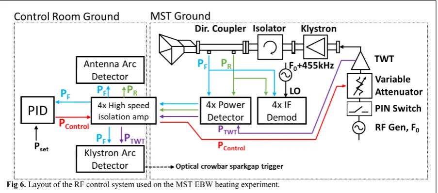
Fig 6. Layout of the RF control system used on the MST EBW heating experiment.
holder onto the window surface. Antennas with both stainless steel and aluminum pillboxes were tested resulting in sputtering of both types on metal onto the window, shown inFig 5 left. Cleaning with a phosphoric acid based cleaner (Oakite 33) successfully removed sputtered aluminum from the surface allowing the window to be returned to service; windows with stainless sputtering were not recoverable with acid based cleaning methods.
2.3 RF power stabilization and control
Adverse effects in klystron power stability due to voltage fluctuations from the HV power supply is corrected with active feedback methods. The voltage dependent gain of a klystron transposes voltage ripple and droop onto the output power. Voltage droop occurs over the 3ms pulse, while ripple exists at ~120kHz, the 6th harmonic of the power supply switching frequency
injected by 3 phase full wave rectification. Noise reduction and improved power stability over the RF pulse duration has been achieved by implementing an automatic gain control (AGC) circuit with a proportional-integral-derivative (PID) control loop.
Layout of the RF system for the EBW experiment is shown in Fig 6. An HP-8673B generator supplies a stable 5.5GHz signal to drive the RF system. Generator output is switched with 10ns rise/fall times at signal level by an HP-11720A PIN diode switch. The windowed RF is fed through a Mini-Circuits HVA-73+ voltage variable attenuator (VVA) for fast power level control as part of the AGC system. The leveled RF signal is boosted up to 20W by a traveling wave tube (TWT) amplifier to drive the klystron; as part of an arc detection system, TWT output power (PTWT) is
monitored and compared to forward power out of the klystron. The klystron amplifies the RF power up to several hundred kW; power from the klystron passes through a CML engineering 25dB circulator functioning as an isolator to protect the klystron from power reflected from the plasma. A directional coupler between the circulator and waveguide antenna measures forward
(PF) and reflected (PR) power which is split into power
and phase detection systems.
A high speed diode detector based on an HP-33330b diode provides high bandwidth power measurement to allow fast arc detection and reduction of high frequency ripple. Attenuation scales the input power to the diode to 10mW/MW. Detector diodes have ground loop isolation on both shield and center coaxial connections and are high-pass filtered at 800MHz to reduce noise pickup. Detector voltage is buffered and amplified by an isolated AD828 OP amp; diodes are terminated with a 100ohm resistor in parallel with the amplifier input to improve rise time. Diode detector system achieves a 19ns delay in response to an RF pulse. Diodes are operated in non-linear mode to improve signal to noise ratio, greatly reducing noise pickup. Calibration of output voltage with a quadratic polynomial fit (R2=0.9998) determines
power from measured voltage. AGC stability and accuracy are not adversely affected by the small non-linearity in power detection since integral gain in the PID control minimizes power error.
Operation of the RF control system in a pulsed magnetic field environment requires ground loop isolation between RF systems in the machine area and control room for safety and noise reduction. A four channel high speed isolation amplifier based on the Cheele CIM1100 isolator module (120MHz bandwidth) separates machine area and control room grounds. Impedance matching of input and output lines to the isolator module with OP amp buffers reduces the effective isolator bandwidth and introduces additional phase shift between input and output signals. The isolator achieves minimal signal distortion at 10MHz, 19ns rise time, and 24ns delay between input and output.
Forward power from the klystron is stabilized by an AGC system using a PID control loop. PF measured by
tuned to have a frequency response inverse to that of the VVA extends the attenuator bandwidth to 2MHz. When tuned to the highest stable gain, negative feedback from the PID control system acts to null out fluctuations in RF power.
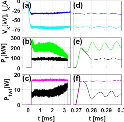
Fig 7. Voltage (light blue) and current (dark blue) supplied to klystron (a) exhibit ripple and droop over the high voltage pulse. Plotted in (b), the resulting change in klystron gain induces ripple and droop in RF power (green) which is stabilized with feedback control (black). Plotted in (c), the feedback controller modulates the output from the TWT (black) driving the klystron in inverse to the ripple and droop to stabilize RF power. TWT output power without feedback is shown in magenta. Zoomed values of (a,b,c) are plotted in (d,e,f). Voltage ripple (d, light blue) and power (e, green) are phase locked to with a constant phase offset. Settling time of feedback controller (e, black) is ~10µs after an initial power spike caused by integrator windup.
Feedback control of RF power with the AGC system achieves a significant reduction in RF power droop and ripple. RF power from the klystron is plotted in Fig 7 (b) with the AGC enabled (black) and disabled (green). In the absence of AGC feedback, noise (e) and droop (b) in power (green) are observed during the pulse corresponding to ripple (d) and droop (a) in voltage (light blue). With the AGC feedback enabled, RF power from the klystron is leveled at ~100kW, and noise is reduced; the inverse of the noise and droop is modulated onto the TWT power feeding the input of the klystron (c,f black). During the leading edge of the RF pulse, the AGC exhibits a slightly underdamped response with a settling time of ~10µs as plotted in (e, black). Initial power overshoot on the leading edge is due to integrator windup as the AGC system remains active when the PIN diode switch inhibits RF power; although it is not detrimental to operation of the system, future systems will address this issue with an integrator reset when RF power is off.
2.4 Klystron protection system
Damage to klystron cathodes due to arcing is prevented with use of a snubber and crowbar circuit to limit arc fault energy. A resistive capacitive (RL) snubber constructed with a 50ohm resistor in parallel with a 400uH inductor is placed in series with the klystron to limit fault current during an arc. The snubber provides additional protection to the power supply by preventing a HV pulse from being reflected on the coaxial cable during an arc. A triggerable spark gap in parallel with the klystron crowbars voltage during a fault, shunting current away from the cathode. The triggered gap is designed to fire at overvoltage conditions determined by gap spacing, self-triggering with high dI/dt conditions, or remote triggering if an imminent arc is predicted. The self-triggering system uses a 3mH inductor in series with the klystron connected across a trigger electrode. High di/dt during a klystron arc triggers the spark gap by providing a high voltage difference across the trigger electrode. Current flow through the trigger electrode is prevented by a 5nF series capacitor. Prior to a klystron arc, gain drops off ~50µs prior to arc initiation. The klystron protection system uses an RF power comparator to remotely trigger the crowbar spark gap if the PF/PTWT power ratio falls
below a set threshold.
2.5 Antenna arcing and coupling
Identification of good and bad shots is required to select valid experimental data and prevent sustained operation at settings resulting in antenna arcing. Although the presence of x-ray emission indicates RF heating within the plasma, the absence of x-ray emission alone is not sufficient to determine if power is coupled into the plasma, or dissipated into an arc within the antenna structure, particularly during the exploration of new parameter space. Analyzing of coupling and fluctuations in reflected power and phase between forward and reflected power are instrumental in determining successful operation of the antenna system.
Phase between forward (PF) and reflected (PR)
power is recovered through digital synchronous demodulation (DSD) [18] of down-converted IF signals shown in Fig 6. An IF frequency at 455kHz is generated by mixing the PF and PR signals with a local oscillator
(LO) locked at 455kHz above the RF generator frequency. RF signals are ground loop isolated on both shield and center coaxial connections and are high-pass filtered at 800MHz to reduce noise pickup. A MITEQ DMX0418L double balanced mixer down-converts PF
and PR signals to 455kHz. Since LO and RF signals are
phase locked, the difference in phase between PF and PR
IF signals provide the phase difference at the RF frequency. The phase diagnostic is useful for edge density fluctuation measurements and identification of antenna arcing.
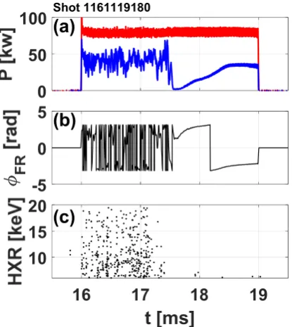
within the waveguide or pillbox window structure presents a load with reduced reflected power fluctuations and phase fluctuations compared to power coupled into the plasma. An example arc is plotted in Fig 8, occurring at ~17.5ms; reflected power fluctuations (a, blue) and phase fluctuations (b) are shown to decrease substantially. Simultaneously, termination of x-ray bremsstrahlung from heated electrons (c) measured with a limiter and target probe [19] is observed. Although reflected power shows an initial dip and subsequent climb, this characteristic is not uniformly observed during all arcs. Reflected power can remain low following an arc; in all cases, high frequency fluctuations in reflected power, and HXR emission, similar to those before 17.5ms, uniformly cease.
0
50
100
(a)
Shot 1161119180-5
0
5
(b)
16
17
18
19
t [ms]
10
15
20
(c)
Fig 8. Characteristic changes in reflected (blue) power and phase due to arcing occurring at the ~17.5ms during an 80kW forward power (red) RF pulse. Substantial reduction in reflected power fluctuations (a) and phase (wrapped to ±π) fluctuations (b) are observed with simultaneous termination of target bremsstrahlung x-rays (c) from heated electrons.
N
et
/F[
]
n=
1
n=
2
n=
3
n=
4
n=
5
n=
6
n=
7
Fig 9. Net vs forward RF power for X-mode (blue) and O-mode(red) launches over a range of plasma currents corresponding to 1st-11th harmonic absorption. Boundaries between harmonics are demoted with vertical red lines.
Coupling from the waveguide antenna is a function of plasma edge conditions [11]; sharp jumps in coupling are not observed when crossing harmonic boundaries. Coupling from the waveguide antenna is plotted in Fig 9 during X mode (blue) and O mode (red) launch; coupling for XB conversion is typically 50-80%, while OXB coupling is typically 30-40%. Lower coupling in the OXB case is expected as optimal launch for OXB occurs at an oblique angle; the lack of a phased array antenna in this experiment mandates a radial launch.
3 Conclusions
RF heating in the RFP has been observed using the EBW on MST. Conditioning of a surplus radar klystron extended achievable pulse width from 18µs to 3ms at a reduced output power; arc damage to dispenser cathodes is recoverable through high temperature conditioning, and preventable with arc detection and LR snubber circuits. Reduction in antenna porthole diameter allows heating at lower harmonics and improves radial accessibility. Feedback control stabilizes RF power from the klystron and reduced voltage ripple induced noise. Coupling in XB conversion is typically 50-80% of forward power. The current configuration favors XB to OXB heating due to a radial launch. Addition of a local limiter to optimize edge density gradient may improve coupling in XB conversion heating, however ceramic covers were shown to limit power handling of the antenna; a coaxial type limiter surrounding the antenna is recommended. This material is based upon work supported by the U.S. Department of Energy Office of Science, Office of Fusion Energy Sciences program under Award No. DE-FC02-05ER54814.
References
[1] J. Preinhaelter, V. Kopecky, J. Plasma Physics. 10, 1 (1973) [2] H. Sugai, Phys. Rev. Lett. 47, 1899 (1981)
[3] H. P. Laqua, et al. Phys. Rev. Lett. 78, 3467 (1997) [4] H. P. Laqua, et al. Phys. Rev. Lett. 90, 075003 (2003) [5] A. Mueck, et al. Phys. Rev. Lett 98,175004 (2007) [6] T. Maekawa, et al. Phys. Rev. Lett. 86, 3783 (2001) [7] V. Shevchenko, et al. Phys. Rev. Lett. 89, 265005 (2002) [8] A. K. Ram, S. D. Schultz Phys. Of Plas. 7,4084 (2000) [9] S. Shiraiwa, et al. Phys. Rev. Lett. 96, 185003 (2006) [10] P.K. Chattopadhyay, et al. Phys. Plasmas 9, 752 (2002) [11] M. Cengher, J.K. Anderson, V. Svidzinski, C.B. Forest. Nuc.
Fusion. 46, 521, (2006)
[12] C.B. Forest, P.K. Chattopadhyay, R.W. Harvey, and A.P. Smirnov, Phys. Plasmas 7, 1352 (2000)
[13] R.N. Dexter, et al. Fus. Sci. and Tech. 19,131 (1991) [14] R. Bilato, et al. Nuc.Fusion. 49, 075020 (2009)
[15] A. H. Seltzman, J. K. Anderson, S. J. Diem, J. A. Goetz, and C. B. Forest Phys. Rev. Lett. 119, 185001 (2017) [16] V. Pericoli et.al. Nuc. Fusion 45, 1085 (2005)
[17] P. J. Fimognari, et al. Plasma. Phys. Cont. Fusion. 52, 095002 (2010)
[18] D. W. Choi, et al. Rev. of Sci. Inst. 57.8 (1986)