Nondestructive Testing
Table of Contents
Chapter No: Name of the Chapter Page No 1 Course daily schedule 1 2 Course Contents 2 3 Introduction NDT processes & their Uses 3 11 4 Identification of weld Discontinuities 12 20 5 Penetrant Testing 21 30 6 Magnetic Particle Testing 31 – 48 7 Ultrasonic Testing 49 60 8 Radiographic Testing 61 77 9 Eddy Current Testing 78 80 10 Comparison and Selection of NDT Methods 81Chapter I
INTRODUCTION
Nondestructive Testing
The field of Nondestructive Testing (NDT) is a very broad, that plays a critical role in assuring that structural components and systems perform their function in a reliable and cost effective fashion. NDT technicians and engineers define and implement tests that locate and characterize material conditions and flaws that might otherwise cause serious accidents such as, planes to crash, reactors to fail, trains to derail, pipelines to burst, and a variety of troubling events.
These tests are performed in a manner that does not affect the future usefulness of the object or material. In other words, NDT allows parts and materials to be inspected and evaluated without damaging them. Because it allows inspection without interfering with a product's final use, NDT provides an excellent balance between quality control and costeffectiveness.
Nondestructive Evaluation
Nondestructive Evaluation (NDE) is a term that is often used interchangeably with NDT. However, technically, NDE is used to describe measurements that are more quantitative in nature. For example, a NDE method would not only locate a defect, but it would also be used to measure something about that defect such as its size, shape, and orientation. NDE may be used to determine material properties such as fracture toughness, ductility, conductivity and other physical characteristics. Uses of NDE · Flaw Detection and Evaluation · Leak Detection, Location Determination · Dimensional Measurements · Structure and Microstructure Characterization · Estimation of Mechanical and Physical Properties · Stress (Strain) and Dynamic Response Measurements · Material Sorting and Chemical Composition Determination
Background on Nondestructive Testing (NDT)
Nondestructive testing has been practiced for many decades. One of the earliest applications was the detection of surface cracks in railcar wheels and axles. The parts were dipped in oil, then cleaned and dusted with a powder. When a crack was present, the oil would seep from the defect and wet the oil providing visual indication indicating that the component was flawed. This eventually led to oils that were specifically formulated for performing these and other inspections and these inspection techniques are now called penetrant testing.
Xrays were discovered in 1895 by Wilhelm Conrad Roentgen (18451923) who was a Professor at Wuerzburg University in Germany. Soon after his discovery, Roentgen produced the first industrial radiograph when he imaged a set of weights in a box to show his colleagues. Other electronic inspection techniques such as ultrasonic and eddy current testing started with the initial rapid developments in instrumentation spurred by technological advances and subsequent defense and space efforts following World War II. In the early days, the primary purpose was the detection of defects. Critical parts were produced with a "safe life" design, and were intended to be defect free during their useful life. The detection of defects was automatically a cause for removal of the component from service.
The continued improvement of inspection technology, in particular the ability to detect smaller and smaller flaws, led to more and more parts being rejected. At this time the discipline of fracture mechanics emerged, which enabled one to predict whether a crack of a given size would fail under a particular load if a particular material property or fracture toughness, were known. Other laws were developed to predict the rate of growth of cracks under cyclic loading (fatigue). With the advent of these tools, it became possible to accept structures containing defects if the sizes of those defects were known. This formed the basis for a new design philosophy called "damage tolerant designs." Components having known defects could continue to be used as long as it could be established that those defects would not grow to a critical size that would result in catastrophic failure. A new challenge was thus presented to the nondestructive testing community.
Mere detection of flaws was not enough. One needed to also obtain quantitative information about flaw size to serve as an input to fracture mechanics calculations to predict the remaining life of a component. These needs, led to the creation of a number of research programs around the world and the emergence of nondestructive evaluation (NDE) as a new discipline.
NDT/NDE Methods
The list of NDT methods that can be used to inspect components and make measurements is large and continues to grow. Researchers continue to find new ways of applying physics and other scientific disciplines to develop better NDT methods. However, there are six NDT methods that are used most often. These methods are Visual Inspection, Penetrant Testing, Magnetic Particle Testing, Electromagnetic or Eddy Current Testing, Radiography, and Ultrasonic Testing.
Visual and Optical Testing (VT)
Visual inspection involves using an inspector's eyes to look for defects. The inspector may also use special tools such as magnifying glasses, mirrors, or borescopes to gain access and more closely inspect the subject area. Visual examiners follow procedures that range fm simple to very complex.
Penetrant Testing (PT)
Test objects are coated with visible or fluorescent dye solution. Excess dye is then removed from the surface, and a developer is applied. The developer acts as blotter, drawing trapped penetrant out of imperfections open to the surface. With visible dyes, vivid color contrasts between the penetrant and developer make "bleedout" easy to see. With fluorescent dyes, ultraviolet light is used to make the bleedout fluoresce brightly, thus allowing imperfections to be readily seen.
Magnetic Particle Testing (MT)
This method is accomplished by inducing a magnetic field in a ferromagnetic material and then dusting the surface with iron particles (either dry or suspended in liquid). Surface and nearsurface imperfections distort the magnetic field and concentrate iron particles near imperfections, previewing a visual indication of the flaw.
Electromagnetic Testing (ET) or Eddy Current Testing
Electrical currents are generated in a conductive material by an induced alternating magnetic field This electrical currents is called eddy currents because they flow in circles at and just below the surface of the material. Interruptions in the flow of eddy currents, caused by imperfections, dimensional changes, or changes in the material's conductive and permeability properties, are detected.
Radiography (RT)
Radiography involves the use of penetrating gamma or Xradiation to examine parts and products for imperfections. An Xray generator or radioactive isotope is used as a source of radiation. Radiation is directed through a part and onto film or other imaging media. The resulting radiograph shows the dimensional features of the part. Possible imperfections are indicated as density changes on the film in the same manner as a medical Xray shows broken bones.
Ultrasonic Testing (UT)
Ultrasonics use transmission of highfrequency sound waves into a material to detect imperfections or to locate changes in material properties. The most commonly used ultrasonic testing technique is pulse echo, wherein sound is introduced into a test object and reflections (echoes) are returned to a receiver from internal imperfections or from the part's geometrical surfaces . crack 0 2 4 6 8 1 0 Initial pulse Crack echo Back surface echo Sound waves
Xray film
Source Rays Object with defect Film Defect Image Film with image Probe Couplant
Acoustic Emission Testing (AE) When a solid material is stressed, imperfections within the material emit short bursts of acoustic energy called "emissions." As in ultrasonic testing, acoustic emissions can be detected by special receivers. Emission sources can be evaluated through the study of their intensity, rate, and location. Leak Testing (LT) Several techniques are used to detect and locate leaks in pressure containment parts, pressure vessels, and structures. Leaks can be detected by using electronic listening devices, pressure gauge measurements, liquid and gas penetrant techniques, and/or a simple soapbubble test.
Test
Method
UT
Xray
Eddy
Current
MPI
LPT
Capital cost Medium to high High Low to medium Medium Low Consumable costVery low High Low Medium Medium
Time of results
Immediate Delayed Immediate Short
delay
Short delay Effect of
geometry
Important Important Important Not too
Important
Not too Important Access
problems
Important Important Important Important Important
Type of defect
Internal Most External External
Near Surface Surface breaking Relative sensitivity
High Medium High Low Low
Operator skill
High High Medium Low Low
Operator training
Important Important Important Important Not
Important Training
needs
High High Medium Low Low
Portability of equipment
High Low High to
medium High to medium High Capabilities Thickness gauging, composition testing Thickness gauging Thickness gauging, grade sorting Defects only Defects only The Relative Uses and Merits of Various NDT Methods
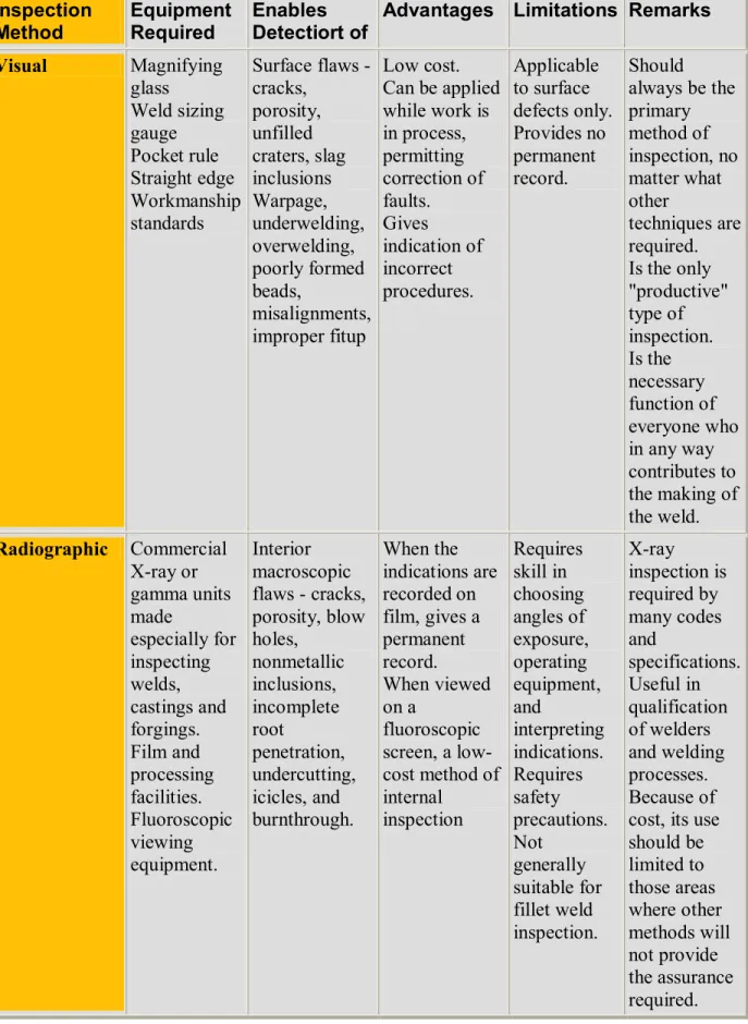
Table 1 Reference Guide to Major Methods for the Nondestructive
Examination of Welds
Inspection Method Equipment Required Enables Detectiort of
Advantages Limitations Remarks
Visual Magnifying glass Weld sizing gauge Pocket rule Straight edge Workmanship standards Surface flaws cracks, porosity, unfilled craters, slag inclusions Warpage, underwelding, overwelding, poorly formed beads, misalignments, improper fitup Low cost. Can be applied while work is in process, permitting correction of faults. Gives indication of incorrect procedures. Applicable to surface defects only. Provides no permanent record. Should always be the primary method of inspection, no matter what other techniques are required. Is the only "productive" type of inspection. Is the necessary function of everyone who in any way contributes to the making of the weld. Radiographic Commercial Xray or gamma units made especially for inspecting welds, castings and forgings. Film and processing facilities. Fluoroscopic viewing equipment. Interior macroscopic flaws cracks, porosity, blow holes, nonmetallic inclusions, incomplete root penetration, undercutting, icicles, and burnthrough. When the indications are recorded on film, gives a permanent record. When viewed on a fluoroscopic screen, a low cost method of internal inspection Requires skill in choosing angles of exposure, operating equipment, and interpreting indications. Requires safety precautions. Not generally suitable for fillet weld inspection. Xray inspection is required by many codes and specifications. Useful in qualification of welders and welding processes. Because of cost, its use should be limited to those areas where other methods will not provide the assurance required.
Magnetic Particle Special commercial equipment. Magnetic powders dry or wet form; may be fluorescent for viewing under ultraviolet light. Excellent for detecting surface discontinuities especially surface cracks. Simpler to use than radiographic inspection. Permits controlled sensitivity. Relatively lowcost method. Applicable to ferromagnetic materials only. Requires skill in interpretation of indications and recognition of irrelevant patterns. Difficult to use on rough surfaces. Elongated defects parallel to the magnetic field may not give pattern; for this reason the field should be applied from two directions at or near right angles to each other. Liquid Penetrant Commercial kits containing fluorescent or dye penetrants and developers. Application equipment for the developer. A source of ultraviolet light if fluorescent method is used. Surface cracks not readily visible to the unaided eye. Excellent for locating leaks in weldments. Applicable to magnetic and nonmagnetic materials. Easy to use. Low cost. Only surface defects are detectable. Cannot be used effectively on hot assemblies. In thinwalled vessels will reveal leaks not ordinarily located by usual air tests. irrelevant surface conditions (smoke, slag) may give misleading indications. Ultrasonic Special commercial equipment, either of the pulseecho or transmission type. Standard reference patterns for interpretation of RF or video patterns. Surface and subsurface flaws including those too small to be detected by other methods. Especially for detecting subsurface laminationlike defects. Very sensitive. Permits probing of joints inaccessible to radiography. Requires high degree of skill in interpreting pulseecho patterns. Permanent record is not readily obtained. Pulseecho equipment is highly developed for weld inspection purposes. The transmission type equipment simplifies pattern interpretation where it is applicable.
Chapter II
IDENTIFICATION OF WELD DISCONTINUITIES
Discontinuities are interruptions in the typical structure of a material. These interruptions may occur in the base metal, weld material or "heat affected" zones. Discontinuities, which do not meet the requirements of the codes or specification used to invoke and control an inspection, are referred to as defects.
General Welding Discontinuities
The following discontinuities are typical of all types of welding. Cracks:
Crack is tight linear separations of metal that can be very short to very long indications. Cracks are grouped as hot or cold cracks. Hot cracks usually occur as the metal solidifies at elevated temperatures. Cold cracks occur after the metal has cooled to ambient temperatures ( delayed cracks).
Cracks can be detected in a radiograph only when they are propagating in a direction that produces a change in thickness that is parallel to the x-ray beam. Cracks will appear as jagged and often very faint irregular lines. Cracks can sometimes appear as "tails" on inclusions or porosity.
Lack of Fusion:
Lack of fusion (Cold Lap) is a condition where the weld filler metal does not properly fuse with the base metal or the previous weld pass material (inter pass cold lap). The arc does not melt the base metal sufficiently and causes the slightly molten puddle to flow into base material without bonding.
Porosity:
Porosity is the result of gas entrapment in the solidifying metal. Porosity can take many shapes on a radiograph but often appears as dark round or irregular spots or specks appearing singularly, in clusters or rows. Sometimes porosity is elongated and may have the appearance of having a tail This is the result of gas attempting to escape while the metal is still in a liquid state and is called wormhole porosity. All porosity is a void in the material it will have a radiographic density more than the surrounding area.
Cluster porosity:
Cluster porosity is caused when flux coated electrodes are contaminated with moisture. The moisture turns into gases when heated and becomes trapped in the weld during the welding process. Cluster porosity appear just like regular porosity in the radiograph but
the indications will be grouped close
Slag inclusions:
Slag inclusions are nonmetallic solid material entrapped in weld metal or between weld and base metal. In a radiograph, dark, jagged asymmetrical shapes within the weld or along the weld joint areas are indicative of slag inclusions.
Incomplete penetration (IP):
Incomplete penetration (IP) or lack of penetration (LOP) occurs when the weld metal fails to penetrate the joint. It is one of the most objectionable weld discontinuities. Lack of penetration allows a natural stress riser from which a crack may propagate. The appearance on a radiograph is a dark area with well-defined, straight edges that follows the land or root face down the center of the weldment.
Root or Internal concavity or suck back is condition where the weld metal has contracted as it cools and has been drawn up into the root of the weld. On a radiograph it looks similar to lack of penetration but the line has irregular edges and it is often quite wide in the center of the weld image.
Internal or root undercut:
Internal or root undercut is an erosion of the base metal next to the root of the weld. In the radiographic image it appears as a dark irregular line offset from the centerline of the weldment. Undercutting is not as straight edged as LOP because it does not follow a ground edge.
External or crown undercut is an erosion of the base metal next to the crown of the weld. In the radiograph, it appears as a dark irregular line along the outside edge of the weld area.
Offset or mismatch:
Offset or mismatch are terms associated with a condition where two pieces being welded together are not properly aligned. The radiographic image is a noticeable difference in density between the two pieces. The difference in density is caused by the difference in material thickness. The dark, straight line is caused by failure of the weld metal to fuse with the land area.
Inadequate weld reinforcement is an area of a weld where the thickness of weld metal deposited is less than the thickness of the base material. It is very easy to determine by radiograph if the weld has inadequate reinforcement, because the image density in the area of suspected inadequacy will be more (darker) than the image density of the surrounding base material.
Excess weld reinforcement :
Excess weld reinforcement is an area of a weld that has weld metal added in excess of that specified by engineering drawings and codes. The appearance on a radiograph is a localized, lighter area in the weld. A visual inspection will easily determine if the weld reinforcement is in excess of that specified by the engineering requirements.
The following discontinuities are peculiar to the TIG welding process. These discontinuities occur in most metals welded by the process including aluminum and stainless steels. The TIG method of welding produces a clean homogeneous weld which when radiographed is easily interpreted.
Tungsten inclusions.
Tungsten is a brittle and inherently dense material used in the electrode in tungsten inert gas ( TIG ) welding. If improper welding procedures are used, tungsten may be entrapped in the weld. Radiographically, tungsten is denser than aluminum or steel; therefore, it shows as a lighter area with a distinct outline on the radiograph.
Oxide inclusions:
Oxide inclusions are usually visible on the surface of material being welded (especially aluminum). Oxide inclusions are less dense than the surrounding materials and, therefore, appear as dark irregularly shaped discontinuities in the radiograph.
Discontinuities in Gas Metal Arc Welds (GMAW)
Whiskers:
Whiskers are short lengths of weld electrode wire, visible on the top or bottom surface of the weld or contained within the weld. On a radiograph they appear as light, "wire like" indications.
Burn-Through:
Burn-Through results when too much heat causes excessive weld metal to penetrate the weld zone. Often lumps of metal sag through the weld creating a thick globular condition on the back of the weld. These globs of metal are referred to as icicles. On a radiograph, burn through appears as dark spots, which are often surrounded by light globular areas (icicles).
Chapter III
PENETRANT INSPECTION
Introduction Liquid penetration inspection is a method that is used to reveal surface breaking flaws by bleedout of a colored or fluorescent dye from the flaw. The technique is based on the ability of a liquid to be drawn into a "clean" surface breaking flaw by capillary action. After a period of time called the "dwell," excess surface penetrant is removed and a developer is applied. This acts as a "blotter." It draws the penetrant from the flaw to reveal its presence.Colored (contrast) penetrants require good white light while fluorescent penetrants need to be viwed in darkened conditions with an ultraviolet "black light".
A very early surface inspection technique involved the rubbing of carbon black on glazed pottery, whereby the carbon black would settle in surface cracks rendering them visible. Later it became the practice in railway workshops to examine iron and steel components by the "oil and whiting" method. In this method, heavy oil commonly available in railway workshops was diluted with kerosene in large tanks so that locomotive parts such as wheels could be submerged. After removal and careful cleaning, the surface was then coated with a fine suspension of chalk in alcohol so that a white surface layer was formed once the alcohol had evaporated. The object was then vibrated and stroked with a hammer, causing the residual oil in any surface cracks to seep out and stain the white coating.
This method was in use from the latter part of the 19th century through to approximately 1940, when the magnetic particle method was introduced and found to be more sensitive for the ferromagnetic iron and steels. Penetrant Inspection Improves the Detect ability of Flaws
The advantage that a liquid penetrant inspection (LPI) offers over an unaided visual inspection is that it makes defects easier to see for the inspector. There are basically two ways that a penetrant inspection process makes flaws more easily seen. First, LPI produces a flaw indication that is much larger and easier for the eye to detect than the flaw itself. Many flaws are so small or narrow that they are undetectable by the unaided eye. The second way that LPI improves the detectability of a flaw is that it produces a flaw indication with a high level of contrast between the indication and the background which also helps to make the indication more easily seen. When a
visible dye penetrant inspection is performed, the penetrant materials are formulated using a bright red dye that provides for a high level of contrast
between the white developer that serves as a background as well as to pull the trapped penetrant from the flaw. When a fluorescent penetrant inspection is performed, the penetrant materials are formulated to glow brightly and to give off light at a wavelength that the eye is most sensitive to under dim lighting conditions.
Basic Processing Steps of a Liquid Penetrant Inspection
1. Surface Preparation: One of the most critical steps of a liquid penetrant inspection is the surface preparation. The surface must be free of oil, grease, water, or other contaminants that may prevent penetrant from entering flaws. The sample may also require etching if mechanical operations such as machining, sanding, or grit blasting have been performed. These and other mechanical operations can smear the surface of the sample, thus closing the defects.
2. Penetrant Application: Once the surface has been thoroughly cleaned and dried, the penetrant material is applied on the surface by spraying, brushing, or immersing the parts in a penetrant bath.
3. Penetrant Dwell: The penetrant is left on the surface for a sufficient time to allow as much penetrant as possible to be drawn from or to seep into a defect. Penetrant dwell time is the total time that the penetrant is in contact with the part surface. Dwell times are usually recommended by the
penetrant producers or required by the specification being followed. The times vary depending on the application, penetrant materials used, the material being inspected, and the type of defect being inspected. Minimum dwell times typically range from 5 to 60 minutes. Generally, there is no harm in using a longer
penetrant dwell time as long as the penetrant is not allowed to dry. The ideal dwell time is often determined by experimentation and is often very specific to a particular application.
4 Excess Penetrant Removal: This is a most delicate part of the inspection procedure because the excess penetrant must be removed from the surface of the sample while removing as little penetrant as possible from defects. Depending on the penetrant system used, this step may involve cleaning with a solvent, direct rinsing with water, or first treated with an emulsifier and then rinsing with water .
5 Developer Application: A thin layer of developer is then applied to the sample to draw penetrant trapped in flaws back to the surface where it will be visible. Developers come in a variety of forms that may be applied by dusting (dry powdered), dipping, or spraying (wet developers).
6 Indication Development: The developer is allowed to stand on the part surface for a period of time sufficient to permit the extraction of the trapped penetrant out of any surface flaws. This development time is usually a minimum of 10 minutes and significantly longer times may be necessary for tight cracks.
7 Inspection: Inspection is then performed under appropriate lighting to detect indications from any flaws that may be present.
8 Clean Surface: The final step in the process is to thoroughly clean the part surface to remove the developer from the parts that were found to be acceptable. Penetrant Testing Materials
The penetrant materials used today are much more sophisticated than the kerosene and whiting first used by railroad inspectors near the turn of the 20th century. Today's penetrants are carefully formulated to produce the level of sensitivity desired by the inspector.
1 Penetrant: Penetrant materials are classified in the various industry and government specifications by their physical characteristics and their performance
Penetrant materials come in two basic types. These types are listed below:
· Type 1 - Fluorescent Penetrants
· Type 2 Visible Penetrants
Fluorescent penetrants contain a dye or several dyes that fluoresce when exposed to ultraviolet radiation. Visible penetrants contain a red dye that provides high contrast against the white developer background. Fluorescent penetrant systems are more sensitive than visible penetrant systems because the eye is drawn to the glow of the fluorescing indication. However, visible penetrants do not require a darkened area and an ultraviolet light in order to make an inspection. Visible penetrants are also less vulnerable to contamination from things such as cleaning fluid that can significantly reduce the strength of a fluorescent indication.
Penetrants are then classified by the method used to remove the excess penetrant from the part. The four methods are listed below: · Method A Water Washable · Method B Post Emulsifiable, Lipophilic · Method C Solvent Removable · Method D Post Emulsifiable, Hydrophilic Water washable (Method A) penetrants can be removed from the part by rinsing with water alone. These penetrants contain some emulsifying agent (detergent) that makes it possible to wash the penetrant from the part surface with water alone. Water washable penetrants are sometimes referred to as selfemulsifying systems.
Post emulsifiable penetrants come in two varieties, lipophilic and hydrophilic. In post emulsifiers, lipophilic systems (Method B), the penetrant is oil soluble and interacts with the oilbased emulsifier to make removal possible. Post emulsifiable, hydrophilic systems (Method D), use an emulsifier that is a water soluble detergent which lifts the excess penetrant from the surface of the part with a water wash. Solvent removable penetrants require the use of a solvent to remove the penetrant from the part.
Properties of good Penetrant
To perform well, a penetrant must possess following important characteristics.
· spread easily over the surface of the material being inspected to provide complete and even coverage. · be drawn into surface breaking defects by capillary action. · remain in the defect but remove easily from the surface of the part. · remain fluid so it can be drawn back to the surface of the part through the drying and developing steps. · be highly visible or fluoresce brightly to produce easy to see indications. · must not be harmful to the material being tested or the inspector.
2 Emulsifiers:
When removal of the penetrant from the defect due to overwashing of the part is a concern, a post emulsifiable penetrant system can be used. Post emulsifiable penetrants require a separate emulsifier to break the penetrant down and make it water washable. Most penetrant inspection specifications classify penetrant systems into four methods of excess penetrant removal. These are listed below:
1. Method A: WaterWashable
3. Method C: Solvent Removable
4. Method D: Post Emulsifiable, Hydrophilic
Method C relies on a solvent cleaner to remove the penetrant from the part being inspected. Method A has emulsifiers built into the penetrant liquid that makes it possible to remove the excess penetrant with a simple water wash. Method B and D penetrants require an additional processing step where a separate emulsification agent is applied to make the excess penetrant more removable with a water wash. Lipophilic emulsification systems are oilbased materials that are supplied in readytouse form. Hydrophilic systems are waterbased and supplied as a concentrate that must be diluted with water prior to use .Lipophilic emulsifiers (Method B) were introduced in the late 1950's and work with both a chemical and mechanical action. After the emulsifier has coated the surface of the object, mechanical action starts to remove some of the excess penetrant as the mixture drains from the part. During the emulsification time, the emulsifier diffuses into the remaining penetrant and the resulting mixture is easily removed with a water spray.
Hydrophilic emulsifiers (Method D) also remove the excess penetrant with mechanical and chemical action but the action is different because no diffusion takes place. Hydrophilic emulsifiers are basically detergents that contain solvents and surfactants. The hydrophilic emulsifier breaks up the penetrant into small quantities and prevents these pieces from recombining or reattaching to the surface of the part. The mechanical action of the rinse water removes the displaced penetrant from the part and causes fresh remover to contact and lift newly exposed penetrant from the surface.
The hydrophilic post emulsifiable method (Method D) was introduced in the mid 1970's and since it is more sensitive than the lipophilic post emulsifiable method it has made the later method virtually obsolete. The major advantage of hydrophilic emulsifiers is that they are less sensitive to variation in the contact and removal time. While emulsification time should be controlled as closely as possible, a variation of one minute or more in the contact time will have little effect on flaw detectability when a hydrophilic emulsifier is used. However, a variation of as little as 15 to 30 seconds can have a significant effect when a lipophilic system is used.
3 Developers
The role of the developer is to pull the trapped penetrant material out of defects and to spread the developer out on the surface of the part so it can be seen by an inspector. The fine developer particles both reflect and refract the incident ultraviolet light, allowing more of it to interact with the penetrant, causing more efficient fluorescence. The developer also allows more light to be emitted through the same mechanism. This is why indications are brighter than the penetrant itself under UV light. Another function that some developers performs is to create a white background so there is a greater degree of contrast between the indication and the surrounding background.
The AMS 2644 and MilI25135 classify developers into six standard forms. These forms are listed below: 1. Form a Dry Powder 2. Form b Water Soluble 3. Form c Water Suspendible 4. Form d Nonaqueous Type 1 Fluorescent (Solvent Based) 5. Form e Nonaqueous Type 2 Visible Dye (Solvent Based)
The developer classifications are based on the method that the developer is applied. The developer can be applied as a dry powder, or dissolved or suspended in a liquid carrier. Each of the developer forms has advantages and disadvantages.
A) Dry Powder
Dry powder developer is generally considered to be the least sensitive but it is inexpensive to use and easy to apply. Dry developers are white, fluffy powders that can be applied to a thoroughly dry surface in a number of ways. The developer can be applied by dipping parts in a container of developer, or by using a puffer to dust parts with the developer. Parts can also be placed in a dust cabinet where the developer is blown around and allowed to settle on the part. Electrostatic powder spray guns are also available to apply the developer. The goal is to allow the developer to come in contact with the whole inspection area.
Unless the part is electrostatically charged, the powder will only adhere to areas where trapped penetrant has wet the surface of the part. The penetrant will try to wet the surface of the penetrant particle and fill the voids between the particles, which brings more penetrant to the surface of the part where it can be seen. Since dry powder developers only stick to the part where penetrant is present, the dry developer does not provide a uniform white background as the other forms of developers do. Having a uniform light background is very important for a visible inspection to be effective and since dry developers do not provide one, they are seldom used for visible inspections. When a dry developer is used, indications tend to stay bright and sharp since the penetrant has a limited amount of room to spread.
B) - Water Soluble
As the name implies, water soluble developers consist of a group of chemicals that are dissolved in water and form a developer layer when the water is evaporated away. The best method for applying water soluble developers is by spraying it on the part. The part can be wet or dry. Dipping, pouring, or brushing the solution on to the surface is sometimes used but these methods are less desirable. Aqueous developers contain wetting agents that cause the solution to function much like dilute hydrophilic emulsifier and can lead to additional removal of entrapped penetrant. Drying is achieved by placing the wet but well drained
part in a recalculating warm air dryer with the temperature held between 70 and 75°F. If the parts are not dried quickly, the indications will will be blurred and indistinct. Properly developed parts will have an even, pale white coating over the entire surface.
C) Water Suspendible
Water suspendible developers consist of insoluble developer particles suspended in water. Water suspendible developers require frequent stirring or agitation to keep the particles from settling out of suspension. Water suspendible developers are applied to parts in the same manner as water soluble developers. Parts coated with a water suspendible developer must be forced dried just as parts coated with a water soluble developer are forced dried. The surface of a part coated with a water suspendible developer will have a slightly translucent white coating.
B) Nonaqueous
Nonaqueous developers suspend the developer in a volatile solvent and are typically applied with a spray gun. Nonaqueous developers are commonly distributed in aerosol spray cans for portability. The solvent tends to pull penetrant from the indications by solvent action. Since the solvent is highly volatile, forced drying is not required. A nonaqueous developer should be applied to a thoroughly dried part to form a slightly translucent white coating.
Preparation of Part
One of the most critical steps in the penetrant inspection process is preparing the part for inspection. All coatings, such as paints, varnishes, plating, and heavy oxides must be removed to ensure that defects are open the surface of the part. If the parts have been machined, sanded, or blasted prior to the penetrant inspection, it is possible that a thin layer of metal may have smeared across the surface and closed off defects. It is even possible for metal smearing to occur as a result of cleaning operations such as grit or vapor blasting. This layer of metal smearing must be removed before inspection.
Contaminants
Coatings, such as paint, are much more elastic than metal and will not fracture even though a large defect may be present just below the coating. The part must be thoroughly cleaned as surface contaminates can prevent the penetrant from entering a defect. Surface contaminants can also lead to a higher level of background noise since the excess penetrant may be more difficult to remove.
Common coatings and contaminates that must be removed include: paint, dirt, flux, scale, varnish, oil, etchant, smut, plating, grease, oxide, wax, decals, machining fluid, rust, and residue from previous penetrant inspections.
Some of these contaminants would obviously prevent penetrant from entering defects and it is, therefore, clear that they must be removed. However, the impact of other contaminants such as the residue from previous penetrant inspections is less clear, but they can have a disastrous affect on the inspection. Take the link below to review some
of the research that has been done to evaluate the effects of contaminants on LPI sensitivity.
A good cleaning procedure will remove all contamination from the part and not leave any residue that may interfere with the inspection process. It has been found that some alkaline cleaners can be detrimental to the penetrant inspection process if they have silicates in concentrations above 0.5 percent. Sodium metasilicate, sodium silicate, and related compounds can adhere to the surface of parts and form a coating that prevents penetrant entry into cracks. Researchers in Russia have also found that some domestic soaps and commercial detergents can clog flaw cavities and reduce the wettability of the metal surface, thus, reducing the sensitivity of the penetrant. Conrad and Caudill found that media from plastic media blasting was partially responsible for loss of LPI indication strength. Microphotographs of cracks after plastic media blasting showed media entrapment in addition to metal smearing.
It is very important that the material being inspected has not been smeared across its own surface during machining or cleaning operations. It is well recognized that machining, honing, lapping, hand sanding, hand scraping, shot peening, grit blasting, tumble deburring, and peening operations can cause a small amount of the material to smear on the surface of some materials. It is perhaps less recognized that some cleaning operations, such as steam cleaning, can also cause metal smearing in the softer materials. Take the link below to learn more about metal smearing and its affects on LPI.
Common Uses of Liquid Penetrant Inspection
Liquid penetrant inspection (LPI) is one of the most widely used nondestructive evaluation (NDE) methods. Its popularity can be attributed to two main factors, which are its relative ease of use and its flexibility. LPI can be used to inspect almost any material provided that its surface is not extremely rough or porous. Materials that are commonly inspected using LPI include the following: · Metals (aluminum, copper, steel, titanium, etc.) · Glass · Many ceramic materials · Rubber · Plastics LPI offers flexibility in performing inspections because it can be applied in a large variety of applications ranging from automotive spark plugs to critical aircraft components.
Penetrant material can be applied with a spray can or a cotton swab to inspect for flaws known to occur in a specific area or it can be applied by dipping or spraying to quickly inspect large areas. At right, visible dye penetrant being locally applied to a highly loaded connecting point to check for fatigue cracking.
Penetrant inspection systems have been developed to inspect some very large components. In this picture, DC10 banjo fittings are being moved into a penetrant inspection system at what used to be the Douglas Aircraft Company's Long Beach, California facility. These large machined aluminum forgings are used to support the number 3 engine in the tail of a DC10 aircraft.
Liquid penetrant inspection is used to inspect of flaws that break the surface of the sample. Some of these flaws are listed below: · Fatigue cracks · Quench cracks · Grinding cracks · Overload and impact fractures · Porosity · Laps · Seams · Pin holes in welds · Lack of fusion or braising along the edge of the bond line As mentioned above, one of the major limitations of a penetrant inspection is that flaws must be open to the surface. Advantages and Disadvantages of Penetrant Testing Like all nondestructive inspection methods, liquid penetrant inspection has both advantages and disadvantages. The primary advantages and disadvantages when compared to other NDE methods are summarized below. Primary Advantages · The method has high sensitive to small surface discontinuities.
· The method has few material limitations, i.e. metallic and nonmetallic, magnetic and nonmagnetic, and conductive and nonconductive materials may be inspected. · Large areas and large volumes of parts/materials can be inspected rapidly and at low cost. · Parts with complex geometric shapes are routinely inspected. · Indications are produced directly on the surface of the part and constitute a visual representation of the flaw. · Penetrant materials and associated equipment are relatively inexpensive.
Primary Disadvantages
· Only surface breaking defects can be detected.
· Only materials with a relative nonporous surface can be inspected. · Precleaning is critical as contaminants can mask defects.
· Metal smearing from machining, grinding, and grit or vapor blasting must be removed prior to LPI. · The inspector must have direct access to the surface being inspected. · Surface finish and roughness can affect inspection sensitivity. · Multiple process operations must be performed and controlled. · Post cleaning of acceptable parts or materials is required. · Chemical handling and proper disposal is require Chapter IV
Magnetic Particle Inspection
Introduction:Magnetic particle inspection is a nondestructive testing method used for surface and near surface defect detection. MPI is a fast and relatively easy to apply and surface preparation is not as critical as it is for some other NDT methods. These characteristics make MPI one of the most widely utilized nondestructive testing methods.
MPI uses magnetic fields and small magnetic particles, such as iron filings to detect flaws in components. The only requirement is that the component being inspected must be made of a ferromagnetic material such iron, nickel, cobalt, or some of their alloys. Ferromagnetic materials are materials that can be magnetized to a level that will allow the inspection to be effective. The method is used to inspect a variety of product forms such as castings, forgings, and weldments. Many different industries use magnetic particle inspection for determining a component's fitnessforuse. Some examples of industries that use magnetic particle inspection are the structural steel, automotive, petrochemical, power generation, and aerospace industries. Underwater inspection is another area where magnetic particle inspection may be used to test items such as offshore structures and underwater pipelines.
Basic Principles
In theory, magnetic particle inspection (MPI) is a relatively simple concept. Consider a bar magnet. It has a magnetic field in and around the magnet. Any place that a magnetic line of force exits or enters the magnet is called a pole. A pole where a magnetic line of force exits the magnet is called a north pole and a pole where a line of force enters the magnet is called a south pole. When a bar magnet is broken in the center of its length, two complete bar magnets with magnetic poles on each end of each piece will result. If the magnet is just cracked but not broken completely in two, a north and south pole will form at each edge of the crack. The magnetic field exits the north pole and reenters the at the south pole. The magnetic field spreads out when it encounter the small air gap created by the crack because the air cannot support as much magnetic field per unit volume as the magnet can. When the field spreads out, it appears to leak out of the material and, thus, it is called a flux leakage field.
If iron particles are sprinkled on a cracked magnet, the particles will be attracted to and cluster not only at the poles at the ends of the magnet but also at the poles at the edges of the crack. This cluster of particles is much easier to see than the actual crack and this is the basis for magnetic particle inspection. The first step in a magnetic particle inspection is to magnetize the component that is to be inspected. If any defects on or near the surface are present, the defects will create a leakage field. After the component has been magnetized, iron particles, either in a dry or wet suspended form, are applied to the surface of the magnetized part. The particles will be attracted and cluster at the flux leakage fields, thus forming a visible indication that the inspector can detect.
History of Magnetic Particle Inspection
Magnetism is the ability of matter to attract other matter. The ancient Greeks were the first to discover this phenomenon in a mineral they named magnetite. Later on Bergmann, Becquerel, and Faraday discovered that all matter including liquids and gasses were affected by magnetism, but only a few responded to a noticeable extent. The earliest known magnetic inspection an object took place as early as 1868. Cannon barrels were checked for defects by magnetizing the barrel then sliding a magnetic compass along the barrel's length. These early inspectors were able to locate flaws in the barrels by monitoring the needle of the compass.
In the early 1920’s, William Hoke realized that magnetic particles could be used with magnetism as a means of locating defects. Hoke discovered that a surface or subsurface flaw in a magnetized material caused the magnetic field to distort and extend beyond the part. This discovery was brought to his attention in the machine shop. He noticed that the metallic grindings from hard steel parts, which were being held by a magnetic chuck while being ground, formed patterns on the face of the parts
which corresponded to the cracks in the surface. Applying a fine ferromagnetic powder to the parts caused a build up of powder over flaws and formed a visible indication. Today, the MPI inspection method is used extensively to check for flaws in a large variety of manufactured materials and components. MPI is used to check materials such as steel bar stock for seams and other flaws prior to investing machining time during the manufacturing of a component. Critical automotive components are inspected for flaws after fabrication to ensure that defective parts are not placed into service. MPI is used to inspect some highly loaded components that have been inservice for a period of time. For example, many components of high performance race cars are inspected whenever the engine, drive train and other systems are overhauled. MPI is also used to evaluate the integrity of structural welds on bridges, storage tanks, pipelines and other critical structures.
Magnetism
Magnets are very common items in the workplace and household. Uses of magnets range from holding pictures on the refrigerator to causing torque in electric motors. The term "magnetic field" simply describes a volume of space where there is a change in energy within that volume. This change in energy can be detected and measured. The location where a magnetic field can be detected exiting or entering a material is called a magnetic pole. Magnetic poles have never been detected in isolation but always occur in pairs and, thus, the name dipole. A bar magnet can be considered a dipole with a north pole at one end and South Pole at the other. A magnetic field can be measured leaving the dipole at the North Pole and returning the magnet at the South Pole. If a magnet is cut in two, two magnets or dipoles are created out of one. This sectioning and creation of dipoles can continue to the atomic level. Therefore, the source of magnetism lies in the basic building block of all matter...the atom.
The Source of Magnetism
All matter is composed of atoms, and atoms are composed of protons, neutrons and electrons. The protons and neutrons are located in the atom's nucleus and the electrons are in constant motion around the nucleus. Electrons carry a negative electrical charge and produce a magnetic field as they move through space. A magnetic field is produced whenever an electrical charge is in motion. The strength of this field is called the magnetic moment.
consider electric current flowing through a conductor. When the electrons (electric current) are flowing through the conductor, a magnetic field forms around the conductor.
The magnetic field can be detected using a compass. The magnetic field will place a force on the compass needle.
Since all matter is comprised of atoms, all materials are affected in some way by a magnetic field. However, not all materials react the same way.
Diamagnetic, Paramagnetic, and Ferromagnetic Materials
In most atoms, electrons occur in pairs. Each electron in a pair spins in the opposite direction. So when electrons are paired together, there opposite spins cause their magnetic fields to cancel each other. Therefore, no net magnetic field exists. Alternately, materials with some unpaired electrons will have a net magnetic field and will react more to an external field. Most materials can be classified as ferromagnetic, diamagnetic or paramagnetic.
Diamagnetic metals have a very weak and negative susceptibility to magnetic fields. Diamagnetic materials are slightly repelled by a magnetic field and the material does not retain the magnetic properties when the external field is removed. Most elements in the periodic table, including copper, silver, and gold, are diamagnetic. Paramagnetic metals have a small and positive susceptibility to magnetic fields. These materials are slightly attracted by a magnetic field and the material does not retain the magnetic properties when the external field is removed. Paramagnetic materials include magnesium, molybdenum, lithium, and tantalum.
Ferromagnetic materials have a large and positive susceptibility to an external magnetic field. They exhibit a strong attraction to magnetic fields and are able to retain their magnetic properties after the external field has been removed. They get their strong magnetic properties due to the presence of magnetic domains. In these domains, large numbers of atoms moments (10 12 to 10 15 ) are aligned parallel so that the magnetic force within the domain is strong. When a ferromagnetic material is in the unmagnitized state, the domains are nearly randomly organized and the net magnetic field for the part as a whole is zero. When a magnetizing force is applied, the domains become aligned to produce a strong magnetic field within the part. Iron, nickel, and cobalt are examples of ferromagnetic materials. Magnetic Domains Ferromagnetic materials get their magnetic properties because the material is made up of small regions known as magnetic domains. In each domain, all of the atomic dipoles are coupled together in a preferential direction. This alignment develops as the material develops its crystalline structure during solidification from the molten state.
During solidification a trillion or more atom moments are aligned parallel so that the magnetic force within the domain is strong in one direction. Even though the domains are magnetically saturated, the bulk material may not show any signs of magnetism because the domains develop themselves are randomly oriented relative to each other. Ferromagnetic materials become magnetized when the magnetic domains within the material are aligned. This can be done by placing the material in a strong external magnetic field or by passing electrical current through the material. Some or all of the domains can become aligned. The more domains are aligned, the stronger the magnetic field in the material. When all of the domains are aligned, the material is magnetically saturated and additional amount of external magnetization force will not cause any increase in its internal level of magnetization. Unmagnetized Material Magnetized Material Magnetic Field Characteristics Magnetic lines of force have a number of important properties, which include: · They seek the path of least resistance between opposite magnetic poles. In a single bar magnet as shown to the right, they attempt to form closed loop from pole to pole. · They never cross one another. · They all have the same strength. · Their density decreases (they spread out) when they move from an area of higher permeability to an area of lower permeability. · Their density decreases with increasing distance from the poles. · They are considered to have direction as if flowing, though no actual movement occurs. They flow from the south pole to the north pole within the material and north pole to south pole in air. Electromagnetic Fields
In most conductors, the magnetic field exists only as long as the current is flowing
the direction of the magnetic field is dependent on the direction of the electrical current in the wire. A threedimensional representation of the magnetic field is shown above. There is a simple rule for remembering the direction of the magnetic field around a conductor. It is called the righthand rule. If a person grasps a conductor in ones right hand with the thumb pointing in the direction of the current, the fingers will circle the conductor in the direction of the magnetic field.
Magnetic Field Produced by a Coil
When a current carrying conductor is formed into a loop or several loops to form a coil, a magnetic field develops that flows through the center of the loop or coil along longitudinal axis and circles back around the outside of the loop or coil. The magnetic field circling each loop of wire combines with the fields from the other loops to produce a concentrated field down the center of the coil. A loosely wound coil is illustrated below to show the interaction of the magnetic field. The magnetic field is essentially uniform down the length of the coil when it is wound tighter.
The strength of a coil's magnetic field increases not only with increasing current but also with each loop that is added to the coil. A long straight coil of wire is called a solenoid and can be used to generate a nearly uniform magnetic field similar to that of a bar magnet. The concentrated magnetic field inside a coil is very useful in magnetizing ferromagnetic materials for inspection using the magnetic particle testing method. Please be aware that the field outside the coil is weak and is not suitable for magnetize ferromagnetic materials.
The Hysteresis Loop and Magnetic Properties
A great deal of information can be learned about the magnetic properties of a material by studying its hysteresis loop. A hysteresis loop shows the relationship between the induced magnetic flux density B and the magnetizing force H. It is often referred to as the BH loop. An example hysteresis loop is shown below.
Plotting the change in magnetic flux B induced a ferromagnetic material while the magnetizing force H is changed generates the hysteresis loop. A ferromagnetic material that has never been previously magnetized or has been thoroughly demagnetized will follow the dashed line as H is increased. As the line demonstrates, the greater the amount of current applied (H+), the stronger the magnetic field in the component (B+). At point "a" almost all of the magnetic domains are aligned and an additional increase in the magnetizing force will produce very little increase in magnetic flux. The material has reached the point of magnetic saturation. When H is reduced back down to zero, the curve will move from point "a" to point "b." At this point, it can be seen that some magnetic flux remains in the material even though the magnetizing force is zero, this is referred to as the point of retentivity on the graph and indicates the remanence or level of residual magnetism in the material. (Some of the magnetic domains remain aligned but some have lost there alignment.) As the magnetizing force is reversed, the curve
moves to point "c", where the flux has been reduced to zero. This is called the point of coercivity on the curve. (The reversed magnetizing force has flipped enough of the domains so that the net flux within the material is zero.) The force required to remove the residual magnetism from the material, is called the coercive force or coercivity of the material.
As the magnetizing force is increased in the negative direction, the material will again become magnetically saturated but in the opposite direction (point "d"). Reducing H to
zero brings the curve to point "e." It will have a level of residual magnetism equal to that achieved in the other direction. Increasing H back in the positive direction will return B to zero. Notice that the curve did not return to the origin of the graph because some force is required to remove the residual magnetism. The curve will take a different path from point "f" back the saturation point where it with complete the loop.
From the hysteresis loop, a number of primary magnetic properties of a material can be determined.
Retentivity A measure of the residual flux density corresponding to the saturation induction of a magnetic material. In other words, it is a material's ability to retain a certain amount of residual magnetic field when the magnetizing force is removed after achieving saturation. (The value of B at point B on the hysteresis curve.)
Residual Magnetism or Residual Flux the magnetic flux density that remains in a material when the magnetizing force is zero. Note that residual magnetism and retentivity are the same when the material has been magnetized to the saturation point. However, the level of residual magnetism may be lower than the retentivity value when the magnetizing force did not reach the saturation level.
Coercive Force The amount of reverse magnetic field which must be applied to a magnetic material to make the magnetic flux return to zero. (The value of H at point C on the hysteresis curve.) Permeability A property of a material that describes the ease with which a magnetic flux is established in the component. Reluctance Is the opposition that a ferromagnetic material shows to the establishment of a magnetic field. Reluctance is analogous to the resistance in an electrical circuit. The shape of the hysteresis loop tells a great deal about the material being magnetized. The hysteresis curves of two different materials are shown in the graph. Magnetic Field Orientation and Flaw Detectability
To properly inspect a component for cracks or other defects, it is important to understand that orientation between the magnetic lines of force and the flaw is very important. There are two general types of magnetic fields that can be established within a component.