Second Harmonic Generation Diagnostic of Layer by
Layer Deposition from Disperse Red 1–Functionalized
Maleic Anhydride Copolymer
(Invited Paper)
G. Aldeaa, H. Gutiérrezb,J. M. Nunzic, G. C. Chitanua, M. Syllac, and B. C. Simionescua a
Romanian Academy, "Petru Poni” Institute of Macromolecular Chemistry Iasi, Aleea Grigore Ghica Voda 41A, 700487, Iasi, Romania.
b
Laboratorio de Electronica - Escuela de Quimica, Facultad de Ciencias, U.C.V.Venezuela.
c
Université d’Angers, PPF Cellules Solaires Photovoltaïques Plastiques, Laboratoire POMA, UMR CNRS N6136, France.
ABSTRACT- Layer-by-layer (LBL) electrostatic assembly of poly-electrolytes is proving to be an increasingly rich and versatile technique for the formation of multilayered thin films with a wide range of electrical, magnetic, and optical properties. In the present work we synthesized a new nonlinear optical (NLO) maleic acid copolymer containing Disperse Red 1 moieties, built-up multilayer assemblies by alternate adsorption of poly (allylamine hydrochloride) (PAH) and maleic copolymer derivative, and carried out an investigation on their second harmonic generation (SHG) properties. The resulting multilayer assemblies exhibit SHG which arises from the non-centrosymmetric alignment of the chromophore in the copolymer. The SHG signal increases with the number of chromophore-containing polymer layers, up to 5 layers. Further assembly reduces the signal.
KEYWORDS: Layer-by-Layer, Electrostatic assembly,
Maleic anhydride copolymer, Second harmonic generation, Nonlinear optics
I. INTRODUCTION
Although the LBL deposition was initially applied to the layering of polyelectrolytes to form alternating polycation/polyanion multilayer assemblies [1]-[2], it has been extended to a wide variety of other interesting charged materials such as functionalized polymers (chromophore-containing polymers, dendrimers and polymeric nanocrystals), dyes, molecules, aggregates, clusters or colloids, metal and semiconductor nanoparticles [3]-[6].
Perhaps one of the fastest growing areas in the LBL technique is the incorporation of electroactive and electro-optical moieties into the films. For this reason, there has been an increasing interest in the use of these films for non-linear optical devices, hole and ion transport, and other applications in which the ordering of the chromophore itself can be critical for the final properties.
The use of maleic anhydride copolymers is attractive because of the variability in their properties achieved through the introduction of different comonomers. Futhermore, these copolymers contain the reactive anhydride unit, which offers possibilities for subsequent chemical modification of the polymer in order to tune the electrical and optical properties. Maleic anhydride
copolymers can be modified by low-molecular-weight compounds containing an active hydrogen (water, alcohols or amines) because of the reactivity of the anhydride functions. From our knowledge only few attempts were made to use maleic acid copolymers as partners in the LBL technique [7]-[10].
Second harmonic generation (SHG) from polymeric materials is one of the functions that has been investigated for years. The second-order non-linear optical effects (NLO) are created when chromophores are arranged in a non-centrosymmetric way. Various attempts have been made to design NLO films. They include the Langmuir-Blodgett method, electric field poling after spin coating, polymer casting on water surface and self assembly techniques [11]-[13]. The alternate assembly is readily applied to polyions that contain chromophores suitable for NLO effects [14]-[16].
In the present work we have synthesized a new maleic acid copolymer containing DR1 moieties and fabricated non-centrosymmetric multilayer films using the LBL process. The multilayer thin films were studied by means of UV-Vis spectroscopy and SHG effects. A theoretical model was used in order to extract the average molecule orientation from the SHG data.
II. EXPERIMENTAL PART A. Polymer synthesis
Maleic anhydride (MA) copolymer (I) with methyl methacrylate (MMA) was obtained by radical polymerization in cyclohexanone [17]. The chemical composition of the copolymer was assessed by conductometric titration with aqueous 0.1 N NaOH in 1:1 (vol) acetone-water mixture [18]. The molecular weight was estimated from viscometric measurements in acetone at 30°C using K and a values from the literature: the
Mark-Houwink-Sakurada constants which depend on temperature and polymer-solvent system [19].
B. Functionalization of the copolymer
The Disperse Red 1 was attached to the copolymer I by chemical modification as follows: a solution of 1.1 g
(3.5 mmol) Disperse Red 1 (DR1) in N-methylpyrrolidone (10 ml) was added slowly, under stirring to a solution of 1 g (3.5 mmol) copolymer I in N-methylpyrrolidone (10 ml), at room temperature. The reaction mixture was heated with stirring to 80 °C for 48 h (previous trials proved that shorter periods of time were unsuccessful). After cooling the reaction mixture was poured into ethyl ether and the transformed copolymer II (M-DR1) was filtered off and dried over night under vacuum. Yield was 60 %. The chemical structures of parent and derivatized copolymers are given in Scheme 1. The corresponding sodium salt of the copolymer II was prepared by hydrolysis with NaOH aqueous solution for 24 h at 40°C.
The DR1 content in the copolymer was determined by UV-Vis spectrometry in acetonitrile, assuming that the molar absorption coefficient of the DR1 structural unit in the copolymer is the same as that of DR1 (λmax=488nm,
1 1
9000 − −
= Lmol cm
ε ). We reached 27 mol percent of
DR1 structural units in the copolymer. By conductometric titration we obtained the conversion X=25% of the anhydride groups to ester groups. X was calculated from the acid number (Ia) estimated using the equation:
80 40
cop a R a
M I X
M I
− =
−
where MCop and MRare the molar weights of the structural unit of the copolymer and of the –OH containing molecule, respectively. The acid number Ia, in g NaOH/g copolymer, is a measure of the carboxylic group content of the copolymer/ester derivative. Results from both methods are in good agreement.
The FT-IR spectrum of the copolymer II reveals that: characteristic anhydride group bands (1855 cm-1, asym C=O; 1784 cm-1, sym C=O; 1226, 942 cm-1, C-O-C stretching) are present but with lower intensity than for the copolymer I. The band at 1730 cm-1 is attributed to the
C=O group from esters (methyl methacrylate moieties and new ester groups formed by DRI derivatization). New signals corresponding to the carboxylic groups formed by derivatization appeared (1690 cm-1, C=O stretching; 1400 cm-1, OH bending; 3450 cm-1, OH stretching,) with low intensity which indicates low degree of conversion. The absorbance peaks centred at 1452, 1494, and 1620 cm−1 are assigned to the C=C stretching vibration in the phenyl ring. The absorbance peaks at 700 and 1043 cm−1 are assigned to the C-H flexural vibration in the phenyl ring, and the absorbance peak at 3030 cm−1 is assigned to C-H stretching vibration in the phenyl ring.
C. Other materials
Disperse Red 1 (DR1) and poly (allylamine hydrochloride) (PAH) were purchased from Aldrich and used without any further purification. Ultrapure water (MilliPore-Q) with a resistivity of 18 M
Ω
x cm was used for all experiments and cleaning steps.III. MULTILAYER FABRICATION
The glass slides were cleaned by immersing for 2h in piranha solution (H2O2/concentrated H2SO4 1: 3 in volume) then washed with deionised water for several times. These treatments generate negative charge on the surface due to partial hydrolysis. The LBL deposition process was carried out in four steps. In the first one, hydrophilized glass slide was immersed in PAH solution for 15 min at room temperature. The attractive force between the positively charged PAH polymer and the negatively charged (OH terminated) surface is expected to coat the glass surface with a monolayer of PAH. In the second step, the coated sample was washed with deionised water several times in order to remove all of the non
-adsorbed materials and dried with a stream of nitrogen gas. In the third dipping step, the substrate coated with a single
CH CH
C C O
O O
)
+
C CH3
COOCH3
CH3 CH2
N
N N NO2
CH2 CH2
HO
CH3 CH2
N N
N
NO2 CH2
CH2 CH2
CH3 1-x
O
x
( )
( )
1.8
1.8
Maleic anhydride-methyl methacrylate copolymer (I)
Disperse Red 1-derivatized copolymer (II) )
( CH CH C C O O (
OH
CH CH
C C O
O O
C COOCH3
CH2
Scheme 1: Reaction of poly (maleic anhydride-co-methyl methacrylate) (I) with Disperse Red 1 (DR1).
layer of PAH was immersed into the polyanion II solution for 15 min. In the last step, the substrate was rinsed and dried as described earlier. All these steps produce a PAH/M-DR1 bi-layer film. This dipping cycle was repeated several times in order to build up thick multilayer films. The deposition process was monitored using UV-Vis absorption spectroscopy on a Perkin – Elmer Lambda 19 UV-Vis-NIR spectrophotometer.
A. SHG Measurements
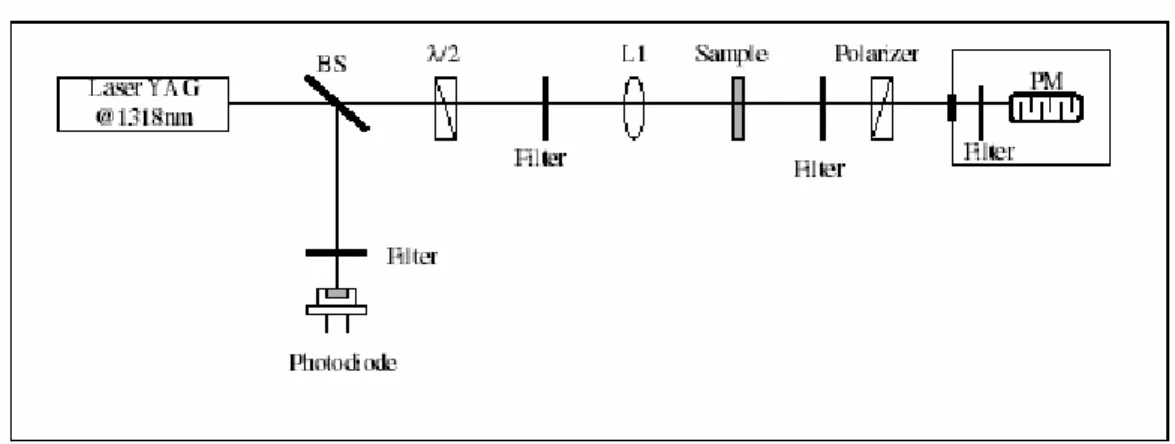
SHG measurements were performed on the layer-by-layer deposited polymer films modified with DR1. The experimental set up is shown in Fig. 1. The light source for SHG was a THALES Q-switched Nd: YAG laser (wavelength: 1.320 nm, pulse duration: 25ns, maximum
pulse energy: 1.6 mJ, repletion rate: 10 Hz). The laser
beam was focused by lens L1 of 10cm focal length, producing a spot size of about 50 µm and directed onto the sample with variable angle of incidence. Polarization of the pumping laser beam was rotated using half-wave plate λ/2.
Either p- or s-polarized components of the transmitted
second harmonic radiation (660nm) were selected with the Glan polarizer. This signal was separated by suitable filters from the fundamental, detected by photomultiplier PM and recorded by a digital oscilloscope (Tektronix TDS-3034) controlled by a personal computer. The sample was set on a computer controlled motorized rotation stage so as to vary the incidence angle of the fundamental beam. SHG signals were recorded at various values of the incidence angle, ranging from -60° to +60°. The energy of the incident beam extracted by beam splitter BS was monitored by an InGaAs photodiode previously calibrated for this setup with respect to a pyrroelectric energy-meter placed in the same place as the sample. SHG data were obtained by averaging over 64 laser shots.
IV. RESULTS AND DISCUSSIONS
Maleic acid copolymers containing DR1 moieties in form of sodium salts can be used for the preparation of multilayer films due to the presence of carboxylic acid groups in each maleic unit. UV-Vis spectroscopy was used to quantify the covalent binding of the DR1 (Scheme 1) as well as to quantify the growth of the multilayer films.
400 500 600 700
0,000 0,002 0,004 0,006 0,008 0,010 0,012 0,014
Abs
or
banc
e
Wavelength (nm)
0 2 4 6
0,000 0,004 0,008 0,012
Abs
orbanc
e
Number of bilayers
400 500 600 700
0,000 0,002 0,004 0,006 0,008 0,010 0,012 0,014
Abs
or
banc
e
Wavelength (nm)
0 2 4 6
0,000 0,004 0,008 0,012
Abs
orbanc
e
Number of bilayers
Fig. 2 UV spectra of the (PAH/M-DR1) multilayer films. The curves from bottom to top are corresponding to the spectra of 1, 2, 3, 4 and 5 bi-layers. Inset shows the dependence of the absorbance on the number of deposited layers.
Figure 2 shows the absorption spectra of the (PAH/M-DR1) multilayer films. The absorption peak of M-DR1 is located at 488 nm and increases linearly with the addition of each bi-layer, as shown in the inset. This plot indicates that layer-by-layer deposited film can be fabricated using PAH/M-DR1. We checked up to 10 layers that absorbance increases monotonically with the number of layers.
Fig. 3 SHG intensity (arbitrary units) as a function of the fundamental beam polarization angle. Signal was detected with s (squares) and p (circles) polarizations. Incidence angle θ was set at 60°.
The efficiency of the alternated deposition of DR1-containing polymer with the polycation PAH was followed also by SHG. Figure 3 shows the dependence of the SHG signal of 5 bi-layers at 60° angle of incidence with the
Fig. 1 Experimental setup for SHG measurements
polarization angle of the fundamental wave, for s and p
polarized detections.
This result suggests that the symmetry of the maleic acid copolymer containing Disperse Red 1 moieties could be regarded as C∞V such as in poled film and Lagmuir-Blodgett film [20]. Let us recall that when the Kleinman symmetry holds, the second order susceptibility tensor for C∞V symmetry is given by:
xzx 2
xzx zxx zyy zzz
0 0 0 0 x 0
x 0 0 0 x 0 0
x x x 0 0 0
< >
⎡ ⎤
⎢ ⎥
= ⎢ ⎥
⎢ ⎥
⎣ ⎦
Fig. 4: SHG intensity (arbitrary units) as a function of the fundamental beam incidence angle from a glass slide having 7 bi-layers. Both laser and signal polarizations were set to p. The continuous curve is the theoretical fit of the data.
Figure 4 shows the dependence of the p-polarized SHG
signal emitted by 7 bi-layers with respect to the angle of incidence for p-polarized incident light. It shows a well contrasted fringe pattern resulting from the interference between the harmonic beam produced by the front and back layers [21-23]. By fitting this curve with a theoretical model of SHG of a thin film (see appendix) we can find both the hyperpolarizability β of the DR1 chromophore in the polymer and the average tilt angle ϑ between the charge-transfer axis of the molecule and the normal to the substrate. The fitted curve is also shown in Figure 4.
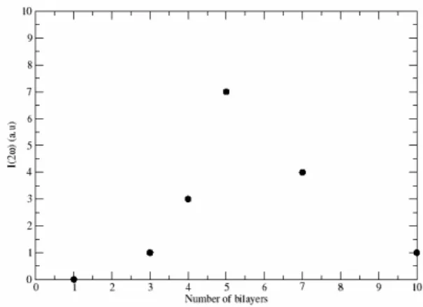
Fig. 5 Dependence of the SHG signal with the number of bi-layers deposited on the substrate.
Figure 5 shows the dependence of the SHG signal with the number of bi-layers. The signal follows almost quadratic increase from 1 to 5 bi-layers and decreases after. We can infer from this behavior that the film is
becoming more and more centrosymmetric above 5 bi-layers. This means that the DR1 chromophores in the successive polymer layers are losing the alignment of the first layers. This is confirmed by the results of the fitting procedure as we obtain an average tilt angle that gets closer to 90° as the number of layer increases (Figure 6).
(a)
(b)
Fig. 6 Dependence of the hyperpolarizability (a) β and (b) tilt angle ϑ of the DR1 moieties on the number of bi-layers as found by theoretical fitting of the data (see appendix).
V. CONCLUSION
We have synthesized a new NLO maleic acid copolymer containing Disperse Red 1 moieties and carried out an investigation on their SHG properties. We have shown that films deposited using the LBL technique can spontaneously assemble into a non-centrosymmetric structure. The uniform orientation of each additional bi-layer is demonstrated by the almost quadratic dependence of the second-harmonic intensity on the number of bi-layers up to 5 bi-bi-layers. The dependence of the second harmonic intensity on the fundamental and second harmonic polarisation indicates that the preferential orientation of the NLO-active groups is perpendicular to the substrate. The SHG signal decreases beyond the 6th bi-layer, indicating bluring of the non-centrosymmetric assembly of the chromophore assembly. In order to obtain practical NLO properties by this technique it is essential to overcome deterioration of the SHG intensity in thicker multilayers. Different techniques have been proposed: the use of larger chromophore loading [24], and the use of cyclodextrin cages [25] are examples. The development of
rational methods to induce and stabilize the orientation of the functional groups still remains a challenge. Such oriented multilayer thin films can also have a great impact on the improvement of the efficiency of polymer solar cells [26]. It was indeed shown that molecule polar orientation in polymer thin films can improve photovoltaic efficiency up to 2 orders of magnitude, provided molecular orientation creates a polarization in the thin film in the same direction as the open circuit voltage.
APPENDIX:THEORETICAL MODEL
By means of the absorption measurements we can estimate the thickness lf of a layer of the polymer film to be about 5 nm. As lf<<λ even for 10 layers, we will take the film as having zero thickness and will take into account the increasing numbers of layers as an increase in the surface density (N) of DR1 chromophores in the film. The film is then characterized by the surface second order susceptibility xs<2>.
Fig. 7 The geometry used in the model
To make the fitting curve of the SHG data we consider the geometry that appears in Figure 7 where n2 is the refractive index of air and n1 is that of the glass substrate. The incident field generates a nonlinear polarization sheet on the film which in turn is the source of the emerging SHG fields. We assume a p-polarized incident plane wave:
(
)
0 21
, exp .
2 ω
< > = ⎛ − − ⎞
⎜ ⎟
⎝ ⎠
P inc
E x z E i px q z t (1)
The surface polarization will have a similar behavior in the x-direction with wave number p, so that
(
,)
exp( )
s s
P x y =P ipx (2)
The generated fields will then have the same dependence on the x, y coordinates. We assume that the layer is thin and that the exciting field may be evaluated as if the layer was absent. Hence the exciting field at z = 0+ is given by,
( )
0 0 1 exp 2 PE < > x =E i⎛⎜ px⎞⎟
⎝ ⎠ (3)
the exciting field at z = h- is given by,
(
)
0 21 21
, exp
2
P P
h
E < > x z =E t < > i⎛⎜ px −q h⎞⎟
⎝ ⎠ (4)
Consequently, the components of the induced nonlinear polarization at each layer will be
2 0
( 0) cos sin
x xzx i i
P z = =χ E θ θ (5a)
and
(
)
2 2 2
0 i i
( 0) cos θ sin θ
z zxx zzz
P z = =E χ +χ (5b)
and
{ (
)
(
)
2 221 12 0 cos sin
p p
x xzx i i
P z =h =x t < >t < > E θ θ
(
)
2 221 12 0
( ) p p cos sin
x xzx i i
P z =h =χ t< > < >t E θ θ (6a)
(
) (
2 2 2 2)
21 12 0 i i
( 0) p p cos θ sin θ
z zxx zzz
P z = = t< > < >t E χ +χ (6b)
The polarization and hence, the generated fields oscillate harmonically at frequency ω′=2ω. Imposing an ongoing
wave condition we may then write the p-components of the field generated in the first film in the following form [27, 28]:
(
)
(
)
' 1 ' 2 ' ' 2 1 ( ) ' ' ' 1 1 2 ' 2 ( )( , ) 4
, z<0 (7a) ( , ) 4
, z>0 (7b)
s s
a x x z z x z
f i px q z
s s
a x x z z x z
f i px q z
E x y i F P F P q e pe
e
q
E x y i F P F P q e pe
q e ε π ε ε π ε − − ⎧ ⎡⎛ ⎞ ⎤ = + + ⎪ ⎢⎜ ⎟ ⎥ ⎢⎝ ⎠ ⎥ ⎣ ⎦ ⎨ ⎡⎛ ⎞ ⎤ = ⎢⎜ + ⎟ + ⎥ ⎢⎝ ⎠ ⎥ ⎣ ⎦
JJG G G
JJG G G
⎪ ⎪ ⎪ ⎪ ⎪ ⎪ ⎪ ⎩ where, 2 2 ' '
1 k p
q′= εj − (8)
k c c
k′=ω′= 2ω =2 (9)
1 2 2 1 2 q q q Fx ′ ′ + ′ ′ ′ = ε
ε (10a)
1 2 2 1 2 1 q q k Fy ′ + ′ ′ = µ µ µ µ (10b) 1 2 2
1
q
q
p
F
x′
′
+
′
′
=
ε
ε
(10c)Similarly for the field
E
b generate in the second film, except that in that case Fx has to be changed to:1 2 2 1 1 q q q Fx ′ ′ + ′ ′ ′ = ε
ε (11)
The primes indicate the corresponding magnitude evaluated at ω′.
The intensity of the outgoing p-polarized SHG field after
the film is then:
1 0 2 12 2 8 c I I I I E E t n c I p b p p b p a b a p > < > < > < > < > < + + = + ′ =
π (12)
where
'
1 T 1 t
( cosθ cosθ )
kh n n
∆Φ = −
To a good approximation the hyperpolarizability of the DR1 moiety has a single non-vanishing element along its charge-transfer axis βccc. This allows us to write the non-vanishing components of χ<2> as
3
2
cos (13 )
1 sin .cos (13 )
2
zzz ccc
zxx zxz ccc
N a
N b
χ β ϑ
χ χ β ϑ ϑ
⎧ = < >
⎪ ⎨
= = < >
⎪⎩
where ϑ is the average tilt angle of the moiety. So we made the fitting to get the best βccc and ϑ [29].
ACKNOWLEDGEMENTS
The authors thank Egide Brancusi project 06163RB for financial support. One of the authors (G.A.) acknowledges financial support from NATO in the form of a basic research fellowship.
H.G. acknowledges financial support from the PCP program Optique Non-Linéaire.
REFERENCES
[1] G. Decher, J.-D. Hong, Makromol. Chem.,
Macromol. Symp. 46, 321 (1991).
[2] G. Decher, Science 277, 1232 (1997).
[3] E. R. Kleinfeld, G. S. Ferguson, Science 265, 370
(1994).
[4] S. Watanabe, S. L. Regen, J. Am. Chem. Soc. 16,
8855 (1994).
[5] I. Kotov, J.H. Dékány, J. H. Fendler, J. Phys.
Chem. 99, 13065 (1995).
[6] B. Liu, W. L.Yu, Y. H. Lai, W. Huang,
Macromolecules 35, 4975 (2002).
[7] Y. Zhang, W. Cao, Langmuir 17, 5021 (2001). [8] M. Muller, S. Heinen, U. Oertel, K. Lunkwitz,
Makromol. Chem.,Macromol. Symp. 64, 197 (2001).
[9] T. Reihs, M. Muller, K. Lunkwitz, Colloids Surf.
A: Physicochem. Eng. Aspects 212, 79 (2003).
[10] G. Aldea, G. C. Chitanu, J-M. Nunzi, S.
Dabos-Seignon, B. C. Simionescu, Nonlinear Optics & Quantum Optics in press.
[11] R. Girling, P. V. Kolinsky, N. A. Cade, J. D.
Earls, I. R. Peterson, Opt. Comm. 55, 289 (1985).
[12]K. D. Singer, J. E. Sohn, S. J. Lalama, Appl.
Phys. Lett. 49, 248 (1986).
[13] W. Schrof, S. Rozouvan, E. Van Keuren, D.
Horn, J. Schmitt, G. Decher, Adv. Mater. 10, 339 (1998).
[14] C. Figura, D. Marciu, Y. Liu, Y. X. Wang, K.
Lenahan, R. O. Claus, J. R. Heflin, Polym. Prepr. Am. Chem. Soc., Div. Polym. Chem. 39, 1126 (1998).
[15] K. E Van Cott, M. Guzy, P. Neyman, C. Brands,
J. R. Heflin, H. W. Gibson, R. A. Davis, Angew. Chem.-Int. Ed. 41, 3236 (2002).
[16] Y. Shimazacki, S. Ito, Langmuir 16, 9478 (2000). [17] G. C. Chitanu, I. L. Zaharia, A. G. Anghelescu,
A. Carpov, Rom. Pat. 117097 (2001).
[18] C. Cazé, J. C. Decroix, C. Loucheux, A. Nicco,
Bull. Soc. Chim. Fr. 11, 2977 (1973).
[19] R. Endo, M. Hattori, M. Takeda, Kobunshi
Kagaku 23, 48 (1972).
[20]B. U. Felderhof, A. Bratz, G. Marowsky, O. Roders, F. Sieverdes, J. Opt. Soc. Am. B 10, 1824 (1993). [21]G. A. Reider, A. J. Schmidt, Opt. Comm. 47, 223
(1983).
[22]F. Kajzar, J. Messier, J. Zyss, I. Ledoux, Opt. Comm. 45, 133 (1983).
[23]D. Lupo, W. Prass, U. Scheunenmann, A.
Laschewsky, H. Ringsdorf, I. Ledoux, J. Opt. Soc. Am. B 5, 300 (1988).
[24]K.M. Lenahan, Y.-X. Wang, Y. Liu, R.O. Claus, J.R. Heflin, D. Marciu, C. Figura, Adv. Mater 10, 853 (1998).
[25]P. Fischer, M. Koetse, A. Laschewsky, E.
Wischerhoff, L. Jullien, A. Persoons, T. Verbiest, Macromolecules 33, 9471 (2000).
[26]L. Sicot, C. Fiorini, A. Lorin, P. Raimond, C. Sentein, J.-M. Nunzi, Solar Energy Materials and Solar Cells 63, 6349 (2000).
[27]J. Jerphagon, S. K. Kurst, J. Appl. Phys. 41, 1667 (1970).
[28]B. U. Felderhof, G. Marowsky, Appl. Phys. B 44, 11 (1987).
[29]F. Eisert, O. Dannenberger, M. Buck, Phys. Rev. B 58, 10860 (1998).