Abstract—In the paper are presented results of simulation and mathematical modelling of the material removal rate of electrodischarge milling process with compressed air as dielectric. There are also presented basic characteristic of the DEDM milling process and comparison of this green machining method with kerosene based EDM milling. Presented results refer to the experiments of micro machining with thick walled electrodes. There are described advantages and drawbacks of this machining method, especially in the field of micro-machining.
Index Terms— dry EDM, EDM milling, mathematical modelling.
I. INTRODUCTION
One of the aspects stimulating development of manufacturing techniques and processes is the increasing need of accuracy, quality of machining and quality of surface layer of the machining. Very important, especially recently, factors are also demands on creating machining methods not harmful for environment. Effective way of reduction of hazardous effects on environment is elimination of liquids used as working media or coolants during machining processes [1].
[image:1.595.58.278.515.675.2]Considering the benefits of dry machining processes, presented in the Figure 1, companies and research centers involved in development of electrodischarge machining are aiming towards reduction of amount of organic based dielectric fluids, by exchanging them with pure water or low concentration water solutions [2].
Figure 1: Benefits of dry electrodischarge machining
Manuscript received March 5, 2010. This work was supported in part by the Polish Ministry of Science and Higher Education under Grant No.: N503 149836 and Grant No.: N503 217638
G. Skrabalak is with the Institute of Advanced Manufacturing Technology, ul. Wroclawska 37a, 30-011 Krakow, Poland (phone: +48-12-63-17-237; fax: ; e-mail: [email protected]).
J. Kozak is with the Institute of Advanced Manufacturing Technology, ul. Wroclawska 37a, 30-011 Krakow, Poland (fax: ; e-mail: [email protected]).
Dry EDM is a 'green' environment friendly EDM technique in which instead of mineral oil based liquid dielectric, gas at high pressure is used as the dielectric medium. This method brings advantages in process performance, like lower tool wear, lower residual thermal stresses and higher precision. Practical application of the DEDM process could bring a lot of advantages for machine makers and machine end users. Important factor is the simplicity of the machine construction, not requiring sophisticated and spacious dielectric circulation and cooling system – the same design, manufacturing and material costs can be reduced. Due to the lack of oils (which are usually flammable), the risk of fire hazards is also lowered to the minimum.
However the method is very promising, it still needs to be investigated in details before practical application at the industrial scale [3,4].
II. MATHEMATICAL MODELLING A. Practical background
A numerical control system enables the workpiece or simple shaped tool electrode to move a previously programmed path. In this way, very complex 2 or 3 dimensional shapes according to the design requirement can be shaped.
However, the tool wear during machining adversely affects the accuracy of the machined components. Tool wear in EDM/DEDM is characterized by the relative tool-electrode wear which is generally defined as ratio tool wear rate to material removal rate, which is the volume of workpiece material removed per unit time):
MRR TWR
=
ν (1)
where TWR, and MRR are the volume material removed per unit time from the tool and the workpiece, respectively.
Changes in dimensions of tool due to wear during machining is expected to reflect in the actual depth of cut and finally in the profile and dimensional accuracy of machined parts. The problem of tool wear in 3D micro and macro EDM using simple shaped electrodes has been addressed by applying the Uniform Wear Method to maintain the electrode shape unchanged and compensate for the longitudinal tool wear [5-7].
Figure 2: Scheme of EDM using the face of end electrode In considered case (Fig.2), the technique of integrating
Study on Dry Electrical Discharge Machining
Uniform Wear Method with CAD/CAM software has been successful in generating very complex 3D cavities, it involves a time consuming, empirical approach for selecting tool paths and machining parameters. Therefore, it is necessary to develop a theoretical model which accounts for the effect of tool wear on the surface profile generation during each pass. As the number of passes can be very large, a corresponding computer simulation software also needs to be developed [6-10].
B. Mathematical modeling of DEDM shaping by end tool electrode
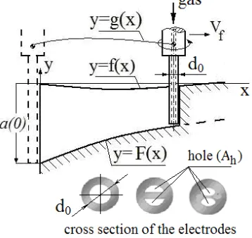
The principal scheme of shaping using the end tool electrode process is presented in Fig. 3. The initial profile of workpiece is given by function y = f(x). The electrode is controlled to move along the tool head path y = g(x). However, the longitudinal tool wear results in the profile of machined surface y = F(x), which is different from g(x).
Figure 3: Principal scheme for mathematical modeling of DEDM by end tool electrode
The purpose of this mathematical modeling and computer simulation is to determine surface profile y = F(x), taking into account the change in tool length which occurs due to the wear of electrode. The final profile depends on input parameters, such as depth of cut a0, initial profile y = f(x), diameter of tool d0 and tool head path y = g(x).
Let us consider the case of machining presented in Fig.3, when the value of slope of the initial surface and the tool path to x- axis is not significant i.e. <<1
dx dg and dx df
In determining the profile of machined surface, the following assumptions are made:
• Changes in tool shape are neglected because the Uniform Wear Method is applying.
• The gap between tool electrode and workpiece is neglected.
Material removal rate MRR is equal:
f V d x F x f
MRR=( ( )− ( ))⋅ 0⋅ (2) and a tool wear rate TWR, defined as the volume of tool material removed per unit time, for g(x) = const. is:
(
)
dt g F d A d TWR h − − = 4 2 0π (3)
or f h h V dx dg dx dF A d dt dx dx dg dx dF A d TWR − − = − − = 4 4 2 0 2 0 π
π (4)
where Vf is feed rate.
After substituting (2) and (4) in (1) for ν , the equation describing the profile of machined surface takes the following form:
( )
dx dg x mf mF dxdF + = +
(5) with initial condition is F(0) = – a(0) (Fig. 3), where
(
2)
0
01 4 /
4 d A d m h π π ν − ⋅
= is the wear factor.
Two tasks can be formulated:
(1) Direct problem - The tool path, g(x), and initial shape of surface, f(x), are known but the resulting shape of the machined surface, F(x), and needs to be predicted.
(2) Inverse problem or control problem - For a required shape of the machined surface, F(x), the tool path, g(x), needs to be determined.
These tasks have been solved numerically using the Finite Difference Method and iterative procedure.
In many cases it is possible to assume, that relative wear during machining is constant (m = const.), i.e.the value ν it is not dependent on the actual depth of cut. For this condition and for f(x) = 0, and g(x)=const., the solution of (5) becomes:
) exp( )
(x a0 mx
F =− − (6) While considering accuracy, the profile is conveniently described in coordinates relative to required allowance, -a0, i.e.:
(
)
[
1 exp( )]
)
(x F a0 a0 mx
h = − − = − − (7)
For more universal application of (6) a non-dimensional form of notations is used. The non-dimensional variables are defined as h =h/ a0 andx=x/L, where L and L is length of tool path. In non-dimensional form, (7) can be written as:
(
A x)
h=1−exp− ⋅ (8) where
(
2)
0
01 4 /
4 d A d L L m A h π π ν − ⋅ = ⋅ = .
The machining accuracy may be improved by control motion of tool electrode. For example, the tool wear can be compensated by moving tool or workpiece along y-axis, to obtain flat surface. In the case when initial surface is flat f(x) = 0 and the depth of cut is equal a0, the required flat shape is F(x) = –a0. Therefore, based on solution, the linear path of tool is needed, which can be described as follows:
x m a H x g
y= ( )= 0− 0⋅ ⋅ (9)
where H0 is initial position of tool head.
For machining with constant feed rate Vf along x-axis, the compensation of the tool wear can be obtained by adding the relative motion of the tool/workpiece with constant feed rate Vy along y-axis equal:
(
)
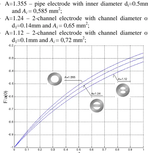
f [image:2.595.78.257.265.434.2]The effect of the type tool-electrode on profiles of machined surface in dimensionless coordinates x/L and F/a(0) is shown in Fig. 4, where
e A
L d A=ν⋅ 0⋅ .
For example, when performing machining process with electrode of outer diameter: d0=1 mm, at the path length of
L=80 mm and tool wear factor ν=0.01(1%), parameter A used for simulation is equal to:
- A=1.355 – pipe electrode with inner diameter di=0.5mm
and Ai = 0,585 mm2;
- A=1.24 – 2-channel electrode with channel diameter of d1=0.14mm and Ai = 0,65 mm2;
[image:3.595.49.288.150.397.2]- A=1.12 – 2-channel electrode with channel diameter of d1=0.1mm and Ai = 0,72 mm2;
Figure 4: Profile of machined surface at different values of A – different electrodes
III. EXPERIMENTAL INVESTIGATIONS A. Test stand setup
Experiments in the field of dry EDM were carried out at the Institute of Advanced Manufacturing Technology (IAMT). Test stand was built on the basis of CNC 3 axes EDM machine of IAMT design. Machine was equipped with the rotating head enabling continuously adjustable rotation of the electrode up to 4000rpm.
During experiments two types of the copper electrodes were used: single hole and 2-channel. The outer diameter of the electrodes was 1mm. Inner hole of the pipe electrode was 0.4mm, outer wall of the 2-channel electrode was 0.3mm. So, contrary to the experiments described by Kunieda at al. [11,12], in case of tests run at IAMT, thick walled electrodes were used.
Gas (compressed air) was supplied through the tool electrode. Set pressures and measured flow-rates are presented in the Table 1.
Electrode type P [bar] Flow rate [l/min]
2 6.4
4 12.5
6 14.5
2 5.3
4 10.7
6 13.9
Table 1: Gas pressure and flow rate
B. Machining conditions
Parameters
During initial series of experiments, the best conditions for DEDM milling process were selected and verified. Optimization criteria were used as follows:
- minimal tool wear ratio (TWR); - maximal material removal rate (MRR); - minimal surface roughness (Ra).
The best results for both types of used electrodes, were achieved for the following parameters:
- free run voltage: 150 V;
- working voltage: during horizontal milling – 90 V during Z-axis drilling – 50V; - pulse ON / OFF time: 40 / 40 µs;
- working current: 3 A; - ignition current: 4 A; - electrode rotation: 4000 rpm; - gas supply pressure: 6 bar;
- electrical conditions: negative electrode (-), positive worpiece (+).
Machining process
For the specified parameters, new series of tests were run, aiming at gathering information on the performance of the DEDM process. Machining process was run layer by layer. Schematic run is presented in Fig. 5.
a)
1 0 0 u m
8 0 m m w o rk p ie c e (+ )
to o l e le c tro d e (-)
[image:3.595.313.529.368.553.2]b) c)
Figure 5: Scheme of the machining process kinematics (a) and machining process (b) and machined surface (c)
Machining results
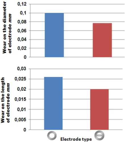
In figures 6 and 7 are presented comparison results of DEDM machining using two types of electrodes. It is noticeable, that in case of using two channel electrode, machining results were slightly better than in case of pipe (single hole) electrode. Better performance of the machining process (observed in surface roughness and geometry of machined cavity) was achieved when 2 channel electrode was used. It may result from the positive effect of:
- better stiffness of the electrode tip;
[image:3.595.47.282.664.761.2]Figure 6: Comparison of surface roughness (Ra[µm]) after
DEDM milling with single hole and 2-channel electrodes
Figure 7: Comparison of electrode wear during DEDM milling with single hole and 2-channel electrodes
Electrode wear model verification
[image:4.595.49.269.227.477.2]Presented results go in common with the results of process modelling and simulation of the surface after machining process (Fig. 4). In Figure 8 are presented profiles of the surface after DEDM milling.
Figure 8: Profiles of the machine surface after DEDM milling with pipe electrode and 2-channel electrode
C.Comparison of electrodischarge milling processes in gas and kerosene
Process conditions
Important part of the conducted research works was comparison of the DEDM milling with EDM milling process in kerosene. To perform this comparison, a series of experiments, using kerosene as dielectric, was run.
Test conditions for kerosene were similar to those used in DEDM, significant difference was:
- working voltage for milling – 50 V;
This set of parameters allowed to perform kerosene EDM milling in optimal conditions (minimal TWR, maximal MRR and minimal Ra). Workpiece was submerged in kerosene,
additionally, there was applied flushing nozzle – dielectric flow through electrode was not applied, as it had no positive influence on the machining results.
For milling process in kerosene the same kinematic conditions were used, as for the DEDM (Fig. 5a).
Machining results
As it was mentioned in part 2, important factor for performing precise EDM machining is prediction of electrode tool wear, as it has significant influence on geometry of machined elements. Comparison of electrode tool wear for both milling processes is presented in Figure 9. It can be noticed, that in case of DEDM, tool wear is about 4 times smaller than in case of kerosene EDM milling.
Figure 9: Electrode tool wear comparison during EDM and DEDM processes
Other important factor, one of the optimization criteria, is the MRR. Comparison of this factor is presented for both methods in Figure 10.
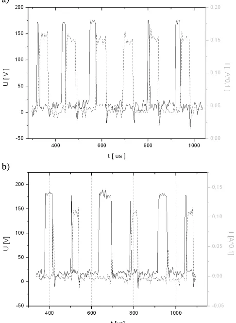
[image:4.595.314.541.370.514.2] [image:4.595.51.278.592.728.2] [image:4.595.307.534.602.763.2]It is noticeable that MRR is significantly higher during DEDM milling process than in case of this process in kerosene. This results from the fact of bigger number of effective working pulses during machining. Voltage and current runs, recorded during machining processes are shown in Figure 11.
a)
[image:5.595.45.288.128.461.2]b)
Figure 11: Voltage and current runs during DEDM milling (a) and EDM in kerosene milling (b) processes
DEDM milling offers its users also much smaller value of coefficient
MRR TWR
=
ν , the same, providing better accuracy of machined shapes than the same process in kerosene.
Figure 12: Comparison of TWR/MRR coefficient for kerosene and dry EDM milling
However DEDM milling provides higher material removal rate, lower tool wear (and resulting from this, better geometry), machine surface is of poorer quality than in case of kerosene EDM milling. Surface roughness (Ra) achieved
during DEDM milling is higher by 0,2 µm (about 20%) than during EDM milling in kerosene.
IV. CONCLUSION
Experiments which were already conducted at IAMT proved the advantages of dry electrodischarge machining. The method is useful not only when thin-walled electrodes are used, like during tests run inJapan [11,12], but also when the active area of the electrode is relatively big (in comparison to the gas supply channels) – more than 50%.
The crucial problem during machining with this environment friendly method is the evacuation of machined material particles out from the working gap. It is very probable that particles get addicted to the electrode. On one hand this phenomena is good for the milling process – having its influence on very low tool wear, but on the other it makes the process useless for machining holes deeper than twice the electrode radius. During this machining process, particles attaching to the electrode are slowing down the process, finally stopping it.
In case of DEDM milling, with thin layers the problem of particles attaching electrode is negligible, as the evacuation them away from the working gap is relatively easy, enforced by the electrode rotation and gas flowing through the centre of electrode. During DEDM milling process, particles of removed material attach to the surface on both sides of machined area. This phenomena can be observed in figure 5c, near the border of machined cavities. This particles cause damages to side surface of machined element, as they are difficult to get rid off. Application of additional gas nozzle, from the side of electrode helps in avoiding this, undesired process. Other solution could be addition of suction nozzle.
DEDM milling process may be very useful especially for micro machining. Due to the tool wear ratio it is more precise than EDM milling in kerosene, what is important aspect in case of machining in micro-scale. Also process of preparing tool paths is much easier, as the tool wear is negligible. However application fields of DEDM in micro-scale are almost borderless (apart from drilling deep holes), application of this way of EDM in macro-scale is rather limited.
REFERENCES
[1] K. Weinert, I. Inasaki, J. W. Sutherland, T. Wakabayashi “Dry Machining and Minimum Quantity Lubrication,” CIRP Annals, Manufacturing Technology, Vol. 53, 2004, Issue 2, pp. 511-537. [2] F. N. Leao, I. R. Pashby, “A review on the use on
environmentally-friendly dielectric fluids in electrical discharge machining,” Journal of Material Processing Technology, Vol. 149, 2004, Issues 1-3, pp. 341-346.
[3] N. M.Abbas, D. G. Solomon, Md.Fuad Bahari, “A review on current research trends in electrical discharge machining (EDM),” International Journal of Machine Tools & Manufacture, Vol. 47, 2007, pp. 1214–1228.
[4] M. Kunieda, B. Lauwers, K. P. Rajurkar, B. M. Schumacher, “Advancing EDM through Fundamental Insight into the Process,” Ann. CIRP, Vol. 54/2, 2005, pp. 64-87.
[5] Z. Y. Yu, T. Masuzawa, M. Fujino, “Micro-EDM for Three-Dimensional Cavities -- Development of Uniform Wear Method,” Annals of the CIRP, Vol. 47/1, 1998, pp. 169-172. [6] K. P. Rajurkar, Z. Y. Yu, “3D Micro EDM Using CAD/CAM,” Annals
of the CIRP, Vol. 49/1, 2000, pp. 127-130.
[image:5.595.47.265.554.694.2][8] P. Bleys, J. P. Kruth, B. Lauwers, “Sensing and compensation of tool wear in milling EDM,” Journal of Material Processing Technology,Vol. 149, 2004, Issues 1-3, pp. 139-146.
[9] P. Bleys, J. P. Kruth, B. Lauwers, “Milling EDM of 3D shapes with tubular electrodes,” Proceedinsg of ISEM XIII, Vol. 2, 2001, pp. 555-567.
[10] J. P. Kruth, P. Bleys, “Machining curvilinear surfaces by NC electro discharge machining,” Proceedinsg of the 2nd International Conference on Machining and Measurement of Sculptured Surfaces – MMSS’2000, Krakow 20-22 September, 2000, pp. 271–294. [11] M. Kunieda, M. Yoshida, “Electrical discharge machining in gas,”
Annals of the CIRP, Vol. 46, 1997, pp. 143-146.