e-ISSN: 2278-067X, p-ISSN: 2278-800X, www.ijerd.com Volume 7, Issue 4 (May 2013), PP. 80-84
Low Power Wide Frequency Range Current Starved
CMOS VCO in 180nm, 130nm and 90nm CMOS
Technology
Varun J. Patel
1, Mehul L.Patel
21,2
Dept. of E&C, L.C. Institute of Technology, Bhandu-384120
Abstract:- This paper describes a design and implementation of Five Stage Current Starved CMOS Voltage Controlled Oscillator for Phase Locked Loop. Current starved VCO is simple ring oscillator consisting of cascaded inverters.The performance comparision is done with repect to power dissipation and phase noise characteristics for three different technology The design is implemented in Mentor Graphics using ELDO SPICE simulator with high oscillation frequency, low power consumption, and low area.
Keywords:- Current starved VCO, oscillators, phase noise, Source Coupled VCO, ring oscillators,
I. INTRODUCTION
A CMOS Voltage controlled oscillator (VCO) is a critical building block in PLL which decides the power consumed by the PLL and area occupied by the PLL. VCO constitute a critical component in many RF transceivers and are commonly associated with signal processing tasks like frequency selection and signal generation. RF transceivers of today require programmable carrier frequencies and rely on phase locked loops (PLL) to accomplish the same. These PLLs embed a less accurate RF oscillator in a feedback loop, whose frequency can be controlled with a control signal. Transceivers for wireless communication system contain low-noise amplifiers, power amplifiers, mixers, digital signal-processing chips, filters, and phase-locked loops. Voltage controlled oscillators play a critical role in communication systems, providing periodic signals required for timing in digital circuits and frequency translation in radio frequency Circuits. Their output frequency is a function of a control input usually a voltage. An ideal voltage-controlled voltage oscillator is a circuit whose output frequency is a linear function of its control voltage. Most application required that oscillator be tunable, i.e. their output frequency be a function of a control input, usually a voltage.
There are two different types of voltage controlled oscillators used in PLL, Current starved VCO and Source coupled VCO [1].In recent years LC tank oscillators have shown good phase-noise performance with low power consumption. However, there are some disadvantages. First, the tuning range of an LC-oscillator (around 10 - 20%) is relatively low when compared to ring oscillators (>50%). So the output frequency may fall out of the desired range in the presence of process variation. Second, the phase-noise performance of the oscillators highly depends on the quality factor of on-chip spiral inductors. For most digital CMOS processes, it is difficult to obtain a quality factor of the inductor larger than three. Therefore, some extra processing steps may be required.
The ring oscillators, however, do not have the complication of the on-chip inductors required for the LC oscillators. Thus the chip area is reduced. In addition to a wide tuning range; ring oscillators with even number of delay cells can produce quadrature-phase outputs [3]. The phase noise performance of ring oscillators is much poorer in general [8], [4]. Also, at high oscillation frequencies, the power consumption of the ring oscillators may not be low which is a key requirement for battery operated devices [10]. To overcome these problems, we work on five stages current starved Oscillator without an LC tank. Finally performances are compared based on their results in different Technology.
II. CIRCUITDESCRIPTION
Fig 1: Current Starved CMOS Voltage Controlled Oscillator in IC Schematic Editor
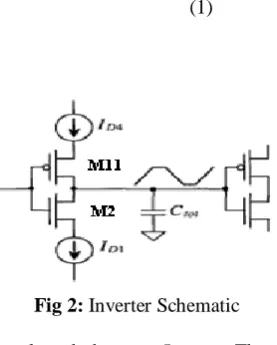
The total capacitance Ctot is given by,
(1)
Where Cox is the oxide capacitance.
Fig 2: Inverter Schematic
The number of stages of the oscillator is selected; there are 5 stages. The centre drain current is calculated as: (2)
Where N is the number of stages of inverter. The sizes of PMOS22 and NMOS21 are determined as:
(3) Where, , it can be shown that the oscillation frequency is:
(4)
=Fcen@VinVCO (5)
Where Td is the time delay above equation gives the centre frequency of the VCO when ID=IDcentre. The VCO stops oscillating, neglecting sub threshold currents, When, VinVCO<Vthn.Thus, Vmin=Vthn and Fmin=0. The max VCO oscillation frequency Fmax is determined by Finding ID when VinVCO=VDD. At the max frequency then, Vmax=VDD.
III. SIMULATIONRESULTS
A. Implemented in 180nm CMOS Technology
Table 1: Simulated Results for Current Starved CMOS VCO in 180nm Technology
Control Voltage (V) Oscillating Frequency(MHz)
0.6 165.23
0.7 438.94
0.8 754.46
0.9 1061.4
1.0 1333.0
1.1 1562.0
1.2 1762.8
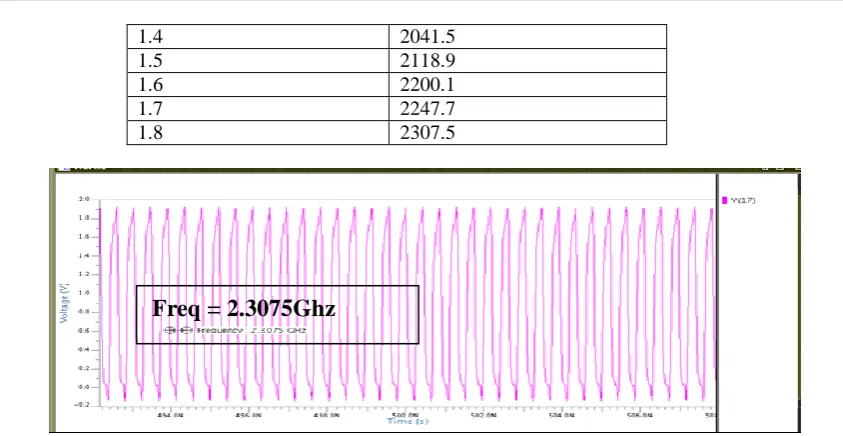
1.4 2041.5
1.5 2118.9
1.6 2200.1
1.7 2247.7
1.8 2307.5
Fig 3: Output Waveform for 1.8v Control Voltage of Current Starved VCO in 180nm Technology.
B. Implemented in 130nm CMOS Technology
Table 2: Simulated Results for Current Starved CMOS VCO in 130nm Technology
Control Voltage (V) Oscillating Frequency(MHz)
0.1 28.237
0.2 154.11
0.3 512.90
0.4 938.95
0.5 1356.5
0.6 2206.2
0.7 2801.0
0.8 3150.0
0.9 3317.9
1.0 3392.3
1.1 3477.9
1.2 3539.9
1.3 3588.8
Fig 4: Output Waveform for 1.3v Control Voltage of Current Starved VCO in 130nm Technology.
C. Implemented in 90nm CMOS Technology
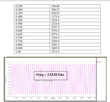
Table 3: Simulated Results for Current Starved CMOS VCO in 90nm Technology Control Voltage (V) Oscillating Frequency(MHz)
0.100 50.00
0.150 99.785
0.200 193.91
Freq = 2.3075Ghz
0.250 350.00
0.300 588.53
0.350 938.95
0.400 1373.4
0.450 1818.6
0.500 2226.8
0.550 2557.9
0.600 2799.2
0.650 2974.1
0.700 3104.4
0.750 3205.0
0.800 3285.2
0.900 3405.0
1.00 3513.4
Fig 5: Output Waveform for 1v Control Voltage of Current Starved VCO in 90nm Technology.
The performance comparision in terms of power dissipation, oscillating frequency, and phase noise, for Five stages current starved CMOS VCO in three differnet Technology is as shown in Table 4.
Table 4: Summary of Results for Current Starved CMOS VCO in Different Technology
Parameters In 180 nm 130 nm In 90 nm
Power Supply
(V) 1.8 1.3 1
Frequency Range 165.23MHz -
2.3073GHz
28.237MHz - 3.5888GHz
50MHz – 3.5134GHz
Phase Noise
(dBc/Hz @
1MHz)
-124.52 -118 -116
Power Dissipation (μW)
1235.7 590.88 240
IV. CONCLUSIONS
This paper shows the Five stages current starved CMOS VCO simulated in ELDO SPICE simulator having low power dissipaton and phase noise as compare to LC oscilator.By observing the Table 4, it can be concluded that the phase noise characteristics of CMOS VCO get worst as we scale down into the Technology node.While the power dissipation of this oscillator will decrease as we go scale down to the Technology node.This circuit is having the application in PLL for low power and low phase noise peformance requirements.
ACKNOWLEDGMENT
Simply to acknowledge the help verbally is not the complete way of expressing the feelings, even though the words, if brought from bottom of the heart can serve the purpose to a considerable extent, this is also a small effort for the same. I am felling great pleasure by acknowledging my guide Prof. Mehul.L.Patel for his valuable motivation and support. He encourage me to express my ideas freely and gave valuable suggestion during the implementation of this circuit.
REFERENCES [1]. B .Razvi, Design of ANALOG CMOS Integrated Circuits,
[2]. William Shing, Tak Yan, and Howard Cam Luong, “A 900-MHz CMOS low-phase- noise voltage-controlled ring oscillator”, IEEE Transactions on Circuits and System II: Analog and Digital Signal Processing,, vol. 48, pp. 216-221,Feb. 2001.
[3]. M. Wegmuller, J. P. von der Weid, P. Oberson, and N. Gisin, “High resolution fiber distributed measurements with coherent OFDR,” in Proc. ECOC’00, 2000, paper 11.3.4, p. 109.
[4]. T. C. Weigandt, B. Kim, and P. R. Gray, ―Analysis of timingjitters in cmos ring oscillators, In Proc. ISCAS, pp. 27-30, June 1994.
[5]. R. Jacob Baker, Harry W. Li & David E. Boyce, CMOS Circuit Design Layout, and Simulation, IEEE Press, 2002.
[6]. W. Xin, Y. Dunshan and S. Sheng, ”A Full Swing And Low Power Voltage-Controlled Ring Oscillator”, Electron Devices and Solid-State Circuits, 2005 IEEE Conference on 19-21 Dec. 2005 Page(s):141 – 143
[7]. Huang Shizhen , Lin Wei , Wang Yutong ,Zheng Li , “Design Of A Voltage-controlled Ring Oscillator Based On MOS Capacitance”, IMECS 2009, March 18 - 20, 2009, Hong Kong.
[8]. Jayna Chawla, “Comparative Study of CMOS Voltage Controlled Oscillators”, Thapar Institute of Engineering & Technology, June, 2006.
[9]. Yalcin Alper Eken, “High Frequency Voltage Controlled Ring Oscillators in Standard CMOS”, Georgia Institute of Technology, November 2003.