© Universiti Tun Hussein Onn Malaysia Publisher’s Office
IJIE
Journal homepage: http://penerbit.uthm.edu.my/ojs/index.php/ijie
The International
Journal of
Integrated
Engineering
ISSN : 2229-838X e-ISSN : 2600-7916
Single Feed Square Aperture Circular Polarized Antenna
S. A. Abu Salim
1*, M. Z. A. Abd. Aziz
1, B. H. Ahmad
11Faculty of Electronics Engineering Computer Engineering,
Universiti Teknikal Malaysia Melaka, Hang Tuah Jaya, 76100 Durian Tunggal, Melaka, MALAYSIA.
*Corresponding Author
DOI: https://doi.org/10.30880/ijie.2019.11.03.032
Received 7 August 2019; Accepted 21 August 2019; Available online 31 August 2019
1. Introduction
Wireless communication has become a significant device that allowed users to communicate. The examples of wireless communication system are satellite system, remote sensing systems, radars, and global positioning systems (GPS). Circular polarized is one of the commonly used in the present wireless communication system due to their many advantages such as lesser phase sensitivity for handheld and portable devices, better mobility, low cost and easy to fabricate [1]. There is various method used in previous studies for CP antenna like stacked microstrip antenna [2], [3], single-fed rectangular microstrip antenna [4], [5], couple method [6] and CP slot antenna.
There are numerous benefits using CP slot antenna which is they do not require strict orientations between transmitters and receivers, low profile and easy fabrication [7]. The slot antennas also have wider impedance bandwidth [8]–[11]. Several CP antenna designs using printed slot antenna have been proposed [7], [12], [13]. A good CP radiation performance can be achieved by printed ring slot antenna [7]. According to [12], a single-fed slot-aperture hybrid antenna for broadband CP operation that consists of U-shaped slot, a rectangular aperture, and a probing strip fed by a microstrip line. Slotted antenna also can be used for bandwidth enhancement by using slotted rectangular microstrip antenna [13].
In this paper, the structure of square-aperture antenna based on study of single feed slot aperture antenna. The antenna is combined with a ground plane reflector to obtain unidirectional pattern for practical application. The antenna will simulate and fabricate to verify the performance of the antenna in terms of return loss, realized gain, axial ratio and radiation pattern.
2. Antenna Configuration
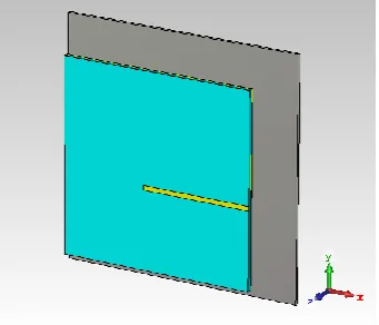
Fig. 1 shows respectively, the view of proposed single feed square aperture without reflector. The antenna is printed on a FR4 substrate of thickness 1.6 mm with dielectric constant Ɛr = 4.4 and loss tangent of δ = 0.019. The antenna consists of square ground plane, probing strip fed and square-aperture. The square ground plane is used with a
Abstract: In recent years, circular polarized antennas become more important in wireless communication systems because of the ability of radiating circular polarized wave. In this paper, the design of single-feed square-aperture antenna with and without reflector towards the circular polarized antenna performance is presented. The antenna made of square ground plane, square-aperture and a probing strip feed by using microstrip transmission line. The design has achieved a target axial ratio, which is less than 3 dB at frequency range of 4 GHz to 6.5 GHz. When a square ground plane reflector is integrated on the CP antenna for the unidirectional pattern, the presented antenna enhanced gain about 8 dB.
length, Lg = 60 mm. To achieve frequency rests around 5.5 GHz, the square-aperture position is tuned starting at end of feed line in the center. The dimension of square-aperture is W = 20 mm. The antenna is fed by using 50-Ω microstrip transmission line with dimension S = 34 mm and c = 1.4 mm. Refer to the Fig. 3 for the geometry of the single fed square aperture and Table 1 for the dimension.
Fig. 1 - Single feed square aperture antenna (Design A)
CP slot/ aperture antenna has a bidirectional radiation pattern. Nevertheless, a unidirectional radiation pattern is needed for practical usage of directive communication link. A square ground plane reflector is used for unidirectional (boresight) radiation. Fig. 2 is the single feed square aperture with reflector. The square ground plane reflector of length Rg = 75 mm separated with air from ground at height h = 13 mm. While adding the reflector, the others antenna dimension is remaining the same.
Fig. 2 - Single feed square aperture antenna with reflector (Design B)
Table 1 - Parameter of antenna
Parameter Dimension (mm)
Lg 60
Mx 19
Mz 25
Fx 34.4
S 34
c 1.4
W 20
h 13
Rg 75
3.
Results and Discussion
The presented antenna with and without reflector were simulated and fabricated using flame retardant 4 (FR4) board as shown in Fig. 4. The simulation was conducted by using Microwave Computer Simulation Technology (CST) Studio simulation software and the fabricated antennas are measured by using anechoic antenna measurement system and network analyzer. The return loss, realized gain, directivity, efficiency, axial ratio and radiation pattern were studied.
Fig. 5 presented the return loss of Design A and Design B. Based on the Fig., the return loss at frequency 5.5 GHz increase from Design A (-19.69 dB) to Design B (-21.95 dB). However, the return loss bandwidth decrease for 11% (37% to 26%). The measurement result for Design B have much difference is due to the fabrication tolerance.Critical conditions for autoignition of non-premixed ethanol flames are shown in Figs. 2 and 3. Fig. 2 shows the temperature of air at autoignition as a function of mass fraction of fuel at the fuel duct exit. The data is obtained at a fixed value of strain rate a2 = 300 s-1. Measured values of Seiser et al. [8] agree well with the numerical calculations as shown in Fig. 2.
Fig. 5 - Return loss
Fig. 7 - Directivity Fig. 8 - Efficiency
Fig. 9 - Axial ratio
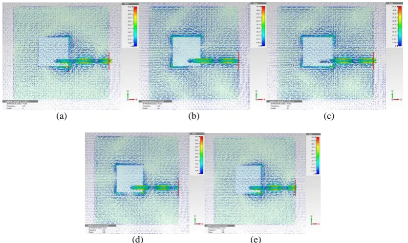
Fig. 6, Fig. 7, and Fig. 8 shows the realized gain, directivity, and efficiency of the antennas. The realized gain and directivity for antenna with reflector are enhanced by about 3.5 dB and 3.9 dB at desired frequency. The simulation result of AR performance for antenna A and B shown in Fig. 9. The AR bandwidth for Design A was about 38% (4.4 GHz to 6.5 GHz), whereas for Design B was 45% (4.0 GHz to 6.5 GHz). The ideal CP is at frequency 5.5 GHz with 0.4 dB AR. The surface current of the antenna to show the working principle of CP radiation pattern can be seen in Fig. 10.
(a) (b) (c)
(d) (e)
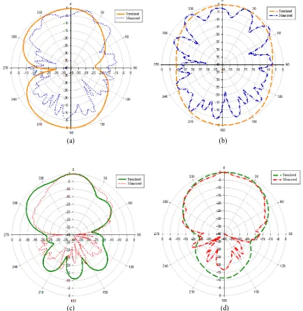
The radiation pattern of antenna at frequency 5.5 GHz are depicted in Fig. 11. Fig. 11(a) and 11(b) shows the simulated and measured patterns in the X-Z and Y-Z planes of Design A, respectively. The result show that the radiation pattern of Design A is look like bidirectional. As mentioned earlier, by integrating the reflector (Design B) the unidirectional pattern can be achieved. Fig. 11(c) and 11(d) presented the antenna for Design B.
(a) (b)
(c) (d)
Fig. 11 - Radiation pattern at 5.5 GHz (a) X-Z cut Design A, (b) Y-Z cut Design A, (c) X-Z cut Design B, and (d) Y-Z cut Design B
The comparison of proposed antenna performance with some referenced antenna as shown in Table 2. The table describe the comparison of size, gain, and AR bandwidth of antennas.
Table 2 - CP antenna comparison
4.
Conclusion
A structure of square-aperture antenna has been proposed in this article. The presented antenna achieved from bidirectional pattern to unidirectional pattern by integrated reflector to the antenna. The return loss, realized gain, axial ratio and radiation pattern of the antenna have been measured and presented. The antenna executes broadband CP radiation. A good axial ratio which is smaller than 3 dB in most areas of the frequency range. The square-aperture antenna with wide bandwidth and high gain is useful in practical application with gain in 8 dB.
References
[1] Agarwal, K., Nasimuddin, and Alphones, A. Wideband circularly polarized slot antenna over meta-surface. 42nd Eur. Microw. Conf., (2012), pp. 609–612, 2012.
[2] Nasimuddin, K., Esselle, P., and Verma, A. K., Wideband circularly polarized stacked microstrip antennas. IEEE Antennas Wirel. Propag. Lett., Volume 6, (2007), pp. 21–24.
[3] Egashira, S., and Nishiyama, E. Stacked microstrip antenna with wide bandwidth and high gain. IEEE Trans. Antennas Propag., Volume 44, No. 11, (1996), pp. 1533–1534.
[4] Haneishi, M., and Yoshida, S. A design method of circularly polarized rectangular microstrip antenna by one-point feed. Electron. Commun. Japan (Part I Commun., Volume 64, No. 4, (1981), pp. 46–54.
[5] Bao, X., Ammann, M., and Ammann, M. J., Dual-frequency dual-sense circularly-polarized slot antenna fed by microstrip line dual-frequency dual-sense circularly-polarized slot antenna fed by microstrip line. IEEE Trans. Antennas Propag., Volume 56, No. 3, (2008), pp. 645–649.
[6] Iwasaki, H. A circularly polarized rectangular microstrip antenna using single-fed proximity-coupled method. IEEE Trans. Antennas Propag., Volume 43, No. 8, (1995), pp. 895–897.
[7] Wong, K. L., Huang, C. C., and Chen, W. S. Printed ring slot antenna for circular polarization. IEEE Trans. Antennas Propag., Volume 50, No. 1, (2002), pp. 75–77.
[8] Jang, Y. Experimental study of wideband printed annular slot antenna with cross-shaped feedline,” Electron. Lett., Volume 38, No. 22, (2002), pp. 1305–1307.
[9] Chen, H. D. Broadband CPW-fed square slot antennas with a widened tuning stub. IEEE Trans. Antennas Propag., Volume 51, No. 8, (2003), pp. 1982–1986.
[10] Bhobe, A., and Holloway, C. Coplanar waveguide fed wideband slot antenna. Electron. Lett., Volume 36, No. 16, (2000), pp. 1340–1342.
[11] Hong, C.-S. Small annular slot antenna with capacitor loading. Electron. Lett., Volume 36, No. 2, (2000), p. 110. [12] Lu, Y. C., Yu, M. J., and Lin, Y. C. A single-fed slot-aperture hybrid antenna for broadband circular polarization
operations. Microw. Opt. Technol. Lett., Volume 54, No. 2, (2012), pp. 412–415.
[13] Sze, J., Wong, K., and Member, S. Slotted rectangular microstrip antenna for bandwidth enhancement. IEEE Trans. Antennas Propag., Volume 48, No. 8, (2000), pp. 1149–1152.
[14] Nosrati, M., Member, S., and Tavassolian, N. Miniaturized circularly polarized square slot antenna with enhanced axial - ratio bandwidth using an antipodal y - strip IEEE Antennas Wirel. Propag. Lett., Volume 16, (2017), pp. 817–820.
[15] Kwame, O. G., Huang, Y., Wen, G., Li, J., and Ampoma, A. E. Broadband circularly polarized square slot antenna with a G-shaped feedline. 2017 IEEE Antennas Propag. Soc. Int. Symp. Proc., Volume 2017-Janua, (2017), pp. 117–118.
[16] H. Zhang, Y. C. Jiao, L. Lu, and C. Zhang, “Broadband circularly polarized square-ring-loaded slot antenna with flat gains,” IEEE Antennas Wirel. Propag. Lett., Volume 16, pp. 29–32, 2017.
[17] Xu, R. Li, J., Qi, Y. X., Guangwei, Y., and Yang, J. J. A design of triple-wideband triple-sense circularly polarized square slot antenna. IEEE Antennas Wirel. Propag. Lett., Volume 16, (2107), pp. 1763–1766.