Abstract—Smart meters are key components in smart grid systems, which can reduce energy demand and thus carbon dioxide emissions from power generation plants. Smart meters automatically sense power consumption in individual households and send the sensed data to a central cloud server. The data can then be mined to determine various environmental parameters that can be used to balance energy supply and demand. Previously, we had developed a stable routing protocol for wireless multi-hop backhaul for broadband mobile systems which normally consists of up to around 10 nodes. Here, we adapt this routing protocol for smart meter systems comprising a maximum of 1000 nodes. The protocol resets an existing route when a new node joins the network. Generally, resetting routes for a large number of nodes renders the system inoperable, and the inoperable period increases as the network size increases. To cope with the issue, this paper proposes a new routing protocol that can add a new node quickly without resetting routing. The proposed protocol demonstrates effectiveness in a 200-node simulation.
Index Terms—Smart grid, smart meter, routing protocol,
tree.
I. INTRODUCTION
Smart grid technology has been promoted to deal with the global energy demand as a solution for the carbon dioxide emissions from power generations. Smart Grid is a plants. The synergistic effects of smart grids are expected to contribute to the resolution of energy and environmental problems [1]. In contrast to conventional power networks that deliver a constant supply of electricity, smart grids, which are networks that are managed by Information and Communication Technology, rely on information and communication technology to collect and communicate supply and demand data. Relative to the existing supply, determining the demand for power in real time can promote the growth of renewable energy. In addition, awareness of the need to use less energy can be increased by making consumption patterns easily accessible.
Manuscript received September 25, 2015; revised December 23, 2015. This work was supported by a Kyuden Technosystems Corporation wireless communication technology development project team, Kyuden Technosystems Corporation Grant No.T135.
Takaaki Suetsugu is with Kyuden Technosystems Corporation, Shimizu, Minami-ku, Fukuoka-city, Fukuoka 815-0031 Japan and He is also with the Department of Faculty of Information Science and Electrical Engineering, Kyushu University, Motooka, Nishi-ku, Fukuoka-city, Fukuoka 819-0395 Japan (e-mail: [email protected], [email protected]).
Hiroshi Furukawa is with the Department of Faculty of Information Science and Electrical Engineering, Kyushu University, Motooka, Nishi-ku, Fukuoka-city, Fukuoka 819-0395 Japan (e-mail: [email protected]).
Smart meter systems are a necessary component of smart grids. Such systems comprise smart meters that collect and transmit usage data, servers that manage the data, and relay devices that aggregate data from smart meters in a given area and transmit to the servers. Smart meters periodically record electricity consumption rates and send that data to power suppliers. The collected data allows suppliers to determine usage patterns, and sending the metered results to consumers can increase their awareness of the need to use less energy.
Smart meter communication systems can include multiple communication methods, such as power-line and wireless communication systems. However, given their relatively low installation costs and flexible installation locations, wireless sensor networks (WSN) have attracted significant attention. A WSN can use relays nodes to communicate with nodes outside its sensor field. Based on the type of relay path, WSNs can generally be divided into two types, i.e., mesh and tree networks.
In a wireless mesh network, each node has information of all nodes in the network as the address and determines the communication path for each packet-forwarding instance. As the size of the network increases, the amount of information managed by a single node also increases. In addition, as a mesh network must construct a transmission route for each communication session, a complex interference avoidance algorithm is required to manage simultaneous communication sessions. To address these problems, a method to decrease radio wave interference has been considered. However, decreasing radio wave interference involves controlling transmission timing and transmission channels, which increases the system cost [2].
In contrast, a wireless tree network manages only its parent node and child nodes and forwards data to a sink node. Thus, the amount of information managed by a node does not increase significantly if the network size expands. In addition, differing from mesh networks, relay routes are predetermined. Thus, a tree network can adapt to changes in radio propagation by introducing periodic route updates.
This study focuses on dynamic tree topology routing in a smart meter system wherein metering results are collected and managed by a sink node. Low-power and Lossy Networks (RPL) has been considered as one of routing methods for constructing tree topology networks [3]. The RPL constructs a tree-type destination-oriented directed acyclic graph (DODAG). In this scheme, each node manages one or several nodes as a parent node and determines a prior parent node to transmit data. Thereby, when one parent is not used, residual parents are used for transmission. However, as parent nodes are determined based on the radio propagation environment when the network is constructed, it is possible
Routing Algorithm for Wireless Multi-hop Networks with
Tree Topology for Smart Meter Systems
for a node registered as a parent node to receive a packet. In this case, if the network changes a prior parent node, transmission may or may not improve. To address these challenges, root information should be updated frequently, or stable routes should be constructed in advance.
Our laboratory has developed a stable routing protocol for wireless backhaul to manage traffic congestion in mobile device networks [4], [5]. This protocol uses wireless backhaul systems that connect access points and construct a stable tree topology network with minimal path loss routing. One metric used for routing is path loss between nodes. Previous studies [4] [5] have reported that this protocol can construct stable routes in a small broadband network composed of dozens of nodes. However, a smart meter system has up to 1000 nodes. This paper assumes that minimum path loss routing is used in a 1000 node network. We investigate potential problems and propose a solution.
This paper proposes a routing algorithm to solve the problems associated with minimum path loss routing in a large network. The remainder of this paper is organized as follows. Section 2 explains minimum path loss routing and identifies potential problems encountered when minimum path loss routing is used in smart meter systems. Section III explains the proposed routing algorithm for a wireless tree topology multi-hop network for smart meters. Section IV describes the simulation scenario used to evaluate the proposed algorithm. Evaluations results are presented in Section V. Section VI presents conclusions and gives suggestions for future work.
II. MINIMUM PATH LOSS ROUTING
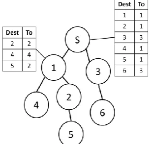
A minimum path loss routing protocol constructs the simplest possible tree network topology. We regard transmission to the sink nodes (root) as upward transmission and transmission to the slave node (leaf) as downward transmission. Each node has a table to manage upward and downward relay nodes. Examples of such tables are shown in Fig. 1.
Fig. 1. Table to manage upward and downward relay nodes.
As shown in Fig. 1, each node is identified by its address. Here S identifies the sink node. All other nodes are slave nodes. A node connected to another node through upward transmission is defined as a parent node. Downward connected nodes are defined as child nodes. Except for the sink node, each node has information about a single parent node and several or no child nodes. Child nodes managed by
one parent node comprise a set of nodes belonging to a subtree that defines the parent node as the root. For example, Fig. 1 shows the downlink tables of the sink node and node 1. Downlink tables associate a destination address (Dest) with a relay node (To). A node sends packets upward to its parent node. When a packet is sent downward, the transmission destination is determined by referring to a downlink table.
Minimum path loss routing uses propagation loss as a metric. Propagation loss is calculated from the received signal strength indicator value between nodes. Routes are determined to minimize propagation losses from the sink node. After the network is constructed, the sink node periodically updates these metrics to maintain stable routes. Routes are determined by two processes: uplink and downlink routing. Uplink routing uses the Bellman–Ford algorithm [6]. After uplink routing, in downlink routing, each node sends a downlink route-learning packet.
A. Uplink Routing
Uplink routing begins when the sink node broadcasts a routing packet. The routing packet includes a sender address and a sum metric from the sink node. A node that receives the routing packet determines the route that minimizes propagation loss from the sink node using the Bellman–Ford algorithm. Then, the node registers the sender node’s address to the uplink table and broadcasts a new routing packet. Even though the node has completed routing and has sent a routing packet, if it receives a routing packet with a superior metric, it rewrites the uplink table and sends a new routing packet.
B. Downlink Routing
Downlink routing is performed after uplink routing. A node that has determined an uplink route sends a downlink-learning packet to an uplink relay node via unicast. The downlink-learning packet contains information about the sending node and nodes that belong to a subtree set that defines the sending node as a root. A node that receives the learning packet adds the node address as the destination (Dest) and the sending node address as a relay (To) to its downlink table. When this process is complete, the node forwards the downlink-learning packet to its parent node. The parent node that receives the forwarded packet repeats the process until the downlink-learning packet reaches the sink node. A node sends the downlink-learning packet when it updates its uplink route or metric.
C. Adding a New Node
In minimum path loss routing, when a new node enters an existing network, the new node sends a participation request to neighboring nodes. A neighboring node that receives this request notifies the sink node, and the sink node broadcasts a reset routing packet (RRP) to the entire network. When a node receives the RRP, it deletes node information from the link table and maximizes its metric. Then, the receiving node broadcasts a RRP. After transmitting the RRP, the sink node broadcasts a routing packet at a predetermined interval.
nodes simultaneously are not practical. In such a large network, several to tens of nodes are installed gradually. When the network is in this transitional phase, service requests will continue; thus, suspending service provision from existing nodes is not an acceptable option. In addition, since smart meter systems use a transmission rate of at most 100 kbps, the proportion of the control frame for routing in the whole network is relatively larger than that of a network with a transmission rate of several tens of Mbps. A method to integrate a new node without resetting routing is presented in the next section.
III. NEW NODE ADDITION
We have proposed a method that gradually optimizes routes by updating metrics. In the proposed method, a new node provisionally connects to an existing network and becomes capable of upward and downward transmission. We refer to this as the instantaneous node addition method (INA). We have used a scheme that is similar to RPL whereby a new node is provisionally connected to the network.
Routing start
Send request
Set wait time
Wait
Receive uplink packet?
Better metric?
Set uplink
Count > wait time
Send downlink packet
New node No
Yes
No
Yes
Yes No
Routing start
Receive request
Set wait time
Wait
Count > wait time
Send uplink packet
Added node
Yes No
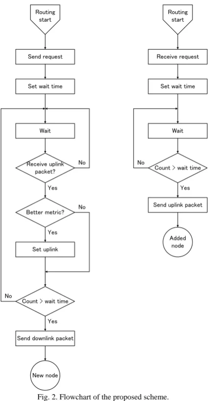
Fig. 2. Flowchart of the proposed scheme.
The RPL constructs a type of DODAG network. A DODAG information object (DIO) packet is used to construct the DODAG. The RPL supports new nodes entering an existing network and constructing routes from
scratch. Initially, when a new node enters an RPL network, it broadcasts a DODAG information solicitation (DIS) to for neighbouring nodes. A new node enters the network by receiving a DIO broadcast by a node that received a DIS. In the INA method, a node that receives a DIS transmits a DIO packet to the new node via unicast. That is because the new node should avoid packet collision. If nodes neighboring the new node update their routes when they receive a DIO packet, there is a probability of occurrence of packet collision.
The flowchart in Fig. 2 illustrates how a new node (left) and existing nodes (right) perform. A new node waits for a specified time after sending a request to participate in the network. If it receives a routing packet within the specified time, the new node calculates the routing packet metric and registers this information to the uplink table. Then, the node waits for the predetermined specified time. Therefore, when the node receives a routing packet after updating the uplink table, if its original metric is superior, it updates the table and continues to wait. If the metric of the previous routing packet is superior, the table is not updated. If the new node has not received another routing packet in the rest time, the node transmits a downlink-learning packet to the sink node by determining if neighboring nodes have completed routing packets. The downlink-learning packet is then forwarded to the sink node. When a downlink-learning packet sent from the new node arrives at the sink node and the new node is registered in the downlink table of the sink node, the node is then capable of upward and downward transmission.
IV. SIMULATION
We evaluate INA method by a simulation with wireless multi-hop cluster. The multi-hop network is composed of a sink node and slave nodes.
We implemented the proposed method to our own developed wireless network simulator, so-called QWS (Kyu-dai Wireless Network Simulator), for performance evaluations. QWS is an event driven system level simulator that can evaluate wireless networks under presence of multiple radio stations being interfered each other. QWS can precisely simulate not only behavior of MAC layer but also physical layer (PHY) phenomenon. Simulation conditions are as follows. PHY and MAC layers are compliant with the IEEE 802.15.4g standard. Barer rate is assumed to be 100 Kbps. A Packet size is assumed to be 255 bytes. Table I summarizes those parameters and some others.
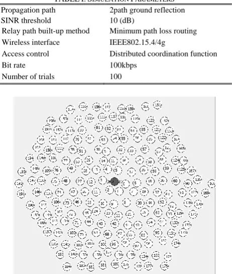
Since a simulation by using 1000 nodes takes too long time, the performance of the network comprising 1000 nodes is to be estimated by extrapolation from simulation results for fewer number of nodes with from 25 to 200. Fig. 3 shows an example of the tree topology in case of 200 nodes randomly placed. A center colored node in Fig. 3 shows a sink node. In simulations, node layouts are randomly defined so as to obtain average performance getting rid of either local best or worst cases.
loss routing. After that, the new node broadcasts a participation request. The nodes that have received the request send a rooting packet to the new node after waiting a random back-off time. This random back-off time is used to avoid packet collision. The random back-off time is calculated as follows:
random_back_off (ms) = 15 (ms) × random (0, x) Random (0, x) gives a number selected from 0 to x randomly.
When the sink node receives a downlink-learning packet from the new node, it assumes that a participation of the new node has completed, and the simulation measures the time from a participation request. Simulations are carried out 100 times so as to measure average time spent in node participation, and the installation places are changed randomly every trial.
TABLEI:SIMULATION PARAMETERS
Propagation path 2path ground reflection SINR threshold 10 (dB)
Relay path built-up method Minimum path loss routing Wireless interface IEEE802.15.4/4g
Access control Distributed coordination function Bit rate 100kbps
Number of trials 100
Fig. 3. Example of the tree topology composed of a sink node and 199 nodes set randomly.
In addition, simulation evaluates the reset routing as a conventional method to compare the time spent in node participation with the proposed method. In the reset routing, described in section 2, a new node sends a participation request and the sink node broadcasts RRP. After transmitting RRP in the network, the sink node also broadcasts a rooting packet. Each node performs uplink-learning by receiving the rooting packet and downlink-learning after that. Downlink-learning protocol starts from low-numbered node in order to reduce the radio wave interference. Actually, some protocol to judge the finish of uplink-learning is necessary. However, in this paper for convenience, it assumes that each node can grasp autonomously.
V. SIMULATION RESULT
In order to clarify how the participation success rate and
the average time spent for participation changes in accordance with the back-off time x, we evaluate these two as the x increases. Participation success rate is the percentage that a new node can register to the sink node at one request. Average time spent for participation is the average time from sending a request to register to the sink node.
First, when the x is 0, the participation success rate is 87 % and the average time spent for participation is 7.7 [s] in the proposed method. The success rate is low for a smart meter system. Since the random back-off time is not used, communication collisions occur between the new node and the nodes outside prospect. When the x is 50, the participation success rate is 90 % and the average time spent for participation is 3.5 [s]. The success rate is still low, but the average time spent becomes shorter. The increase of the x enables the new node to avoid communication collision. As the x increases, it improves the participation success rate and the average time spent for participation. When the x is 100, the participation success rate is 100% and the average time spent for participation is 2.5 [s]. The participation rate is enough high and the average time spent is enough short to use in a smart meter system. In the reset routing, when the network waits until the participation success rate is 100%, the average time spent for participation is 7.5 [s]. If the proposed method takes sufficient back-off time, it is faster than the reset routing.
The proposed method needs the large back-off time in case that many nodes have arranged around a new node. Since the smart meter systems could be used in a built-up area, the back-off time has to take a sufficient length.
Fig. 4. Time course of participation of a new node.
Fig. 4 illustrates average time spent from a new node set to registration to the sink node. Dashed line and solid line shows approximating curve of simulation results on the reset routing and the proposed method, respectively. The time spent for the participation in the network comprising 1000 nodes is extrapolated, and it is about 100 [s] for the reset routing and about 26 [s] for the proposed method. The average time spent for participation of the proposed method is shorter than the reset routing, and the difference of the average time spent between the proposed method and the reset routing becomes larger as the number of nodes increases. Since only the nodes which have been installed around a new node communicate the new node at first, the increase of the number of nodes in the network does not influence the time for routing by the proposed method in comparison with the reset routing.
center gray circle shows a new node. The upper figure shows the situation that has added a new node to the network which has completed the routing. The below left figure shows the situation that has made routing by the proposed method, and the below right figure shows the situation that has renewed the network by using the reset routing. Comparing these two situations, the existing routes have not changed in the proposed method, but the network has become quite a different one in the reset routing. The interference of a new node changes metrics of neighboring nodes. Since the proposed method does not change the existing routes immediately, it keeps the service provision from smart meter systems when a new node enters the network. However, the proposed method does not make the best routing in terms of the minimum pass loss routing. To solve this problem, the sink node periodically updates the routes in the network while continuously providing a service as it is.
Fig. 5. Examples of route changes by updating metrics.
VI. CONCLUSION
This paper introduced routing algorithm for wireless multi-hop networks with tree topology for smart meter systems. In the proposed algorithm, when a new node enters an existing network, it provisionally connects and gradually optimizes in the process of stabilizing the whole network. The advantage is larger as a given tree is larger. The effectiveness of the proposed method was also confirmed through simulation.
Since some of wireless sensor applications such as a smart metering system have been considered to implement more than a few hundred sensor nodes in a single deployment, benefit of the proposed scheme will be more remarkable. On the other hand, since this paper could not cover evaluations for such a large scale wireless sensor network, the authors
would like to reserve the topic as a future study. Another future study includes conducting a study of an effective routing algorithm in tree-based networks to improve the overall performance of WSNs and judgement the finish timing of uplink-learning to evaluate in the more correct situation.
ACKNOWLEDGMENT
The authors thank to Mr. Shunya Matsunaga for his contributions on preliminary studies regarding routing algorithm and evaluations.
REFERENCES
[1] E. Ancilloti, R. Bruno, and M. Conti, “The role of the RPL routing protocol for smart grid communications,” IEEE Communications Magazine, vol. 51, pp. 75-83, January 2013.
[2] IEEE Standard for Local and Metropolitan Area Networks—Part.15.4: Low-Rate Wireless Personal Area Networks (LR-WPANs) Amendament1: MAC Sublayer, IEEE Standard 802.15.4e, Apr. 2012. [3] T. Winter et al. RFC6550 RPL: IPv6 Routing Protocol for Low-Power
and Lossy Networks. [Online] Available: http://www.ietf.org/rfc/rfc6550.txt
[4] G. Jin and H. Furukawa, “A stable routing algorithm based on the succesive average of RSSI between relay nodes,” Wireless Communication Systems, vol. 109, pp. 65-70, February.
[5] G. Jin and H. Furukawa, “A stable routing protocol for wireless backhaul,” IEICE Transactions B. Communications, J94-B(4), pp. 615-628, April 2011.
[6] D. B. Johnson and D. A. Maltz, “Dynamic source routing in ad-hoc wireless networks," in Mobile Computing, T. Imielinski and H. Korth, eds., Kluwer, 1996, pp. 153-181.
Takaaki Suetsugu received the B.E. and M.E. in
information engineering from Kyushu University in 2008 and 2010, respectively. Since 2010, he has been with Kyuden Technosystems Corporation where he is in charge of developments on smart meter for PLC and 920MHz specified low power radio. Currently, he is studying toward his Ph.D. degree at the Department of Intelligent Systems, Kyushu University. His research interacts include smart grid wireless communication systems and wireless tree networks. He is a student member of the IEICE.
Hiroshi Furukawa received the B.E. degree in