A High Speed Binary Floating Point Multiplier
using Dadda Algorithm
Prakhi Agrawal1, Prof. Shravan Sable2, Dr. Rita Jain3
M-Tech Research Scholar, Department of Electronics & Communication Engineering
Lakshmi Narain College of Technology, Bhopal, (M.P.) 1
Research Guide, Department of Electronics & Communication Engineering
Lakshmi Narain College of Technology, Bhopal, (M.P.) 2
HOD, Department of Electronics & Communication Engineering
Lakshmi Narain College of Technology, Bhopal, (M.P.) 3
Abstract: In this paper area efficient Multiplier architecture is developed using Dadda Multiplier. The proposed Multiplier Algorithm takes reduced area than the previous one and the significant delay is also lower than the previous designs. The number of slices in the previous designs is 648 and in our proposed Dadda Multiplier architecture utilizes only 402 slices then area is reduced up to 30%. As shown in the design as well as the simulation results the proposed Multiplier architecture area as well as delay is better.
Keywords:Double Precision, Dadda Multiplier, Floating Point, Area Efficient.
I. INTRODUCTION
Digital arithmetic operations are very important in the design of digital processors and application-specific systems. Arithmetic circuits form an important class of circuits in digital systems. With the remarkable progress in the very large scale integration (VLSI) circuit technology, many complex circuits, unthinkable yesterday have become easily realizable today. Algorithms that seemed impossible
to implement now have attractive implementation
possibilities for the future. This means that not only the conventional computer arithmetic methods, but also the unconventional ones are worth investigation in new designs. The notion of real numbers in mathematics is convenient for hand computations and formula manipulations. However, real numbers are not well-suited for general purpose computation, because their numeric representation as a string of digits expressed in, say, base 10 can be very long or even infinitely long. Examples include π, e, and 1/3. In practice, computers store numbers with finite precision. Numbers and arithmetic used in scientific computation should meet a few general criteria:-
Numbers should have modest storage requirements.
Arithmetic operations should be efficient to carry. A level of standardization, or portability, is desirable–results obtained on one computer should closely match the results of the same computation on other computers Internationally-standardized methods for representing numbers on computers have been established by the IEEE-754 standard to satisfy these basic goals [1].
An arithmetic unit based on IEEE standard for floating point numbers has been implemented on FPGA Board. The arithmetic unit implemented has a 64-bit processing unit
which allows various arithmetic operations such as, Addition, Subtraction, Multiplication, Division and Square Root on floating point numbers. Each operation can be selected by a particular operation code. Synthesis of the unit for the FPGA board has been done using XILINX-ISE. The IEEE standards mandate exact representations for binary single and double precision floating-point formats [4], as well as more flexible guidelines for single-extended and double-extended formats. Quadruple precision is not yet an official standard, although at present, an IEEE working group is standardizing it [12]. The IEEE standards have been extraordinarily successful in ensuring a level of portability
for computer arithmetic across a vast array of
implementations and disparate architectures. Since these standards are the basis for virtually all floating-point computation, it is important to understand their details.
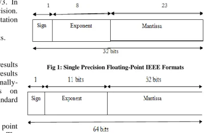
Fig 1: Single Precision Floating-Point IEEE Formats
Fig.1 and Fig.2 illustrates the IEEE standard binary single precision floating-point formats, along with the IEEE standard for double precision floating-point format. Single precision has 1 sign bit, 8 exponent bits, and 23 mantissa bits. Double precision has 1 sign bit, 11 exponent bits, and 52 mantissa bits. The IEEE format requires normalization, and since it uses radix 2, it is known a prior that the first bit of the mantissa is a 1, which means that it can be implied. This implied bit gives IEEE formats an extra bit of mantissa. For example, IEEE single precision has effectively 24 bits of mantissa, rather than the 23 which are expressed in the external representation as shown in Fig 1.
Floating Point Numbers
The term floating point is derived from the fact that there is no fixed number of digits before and after the decimal point, that is, the decimal point can float. There are also representations in which the number of digits before and after the decimal point is set, called fixed-point representations. In general, floating point representations are slower and less accurate than fixed-point representations, but they can handle a larger range of numbers. Floating Point Numbers are numbers that can contain a fractional part. For e.g. following numbers are the floating point numbers: 3.0, -111.5, ½, 3E-5 etc.
Floating-point arithmetic is considered an esoteric subject by many people. This is rather surprising because floating-point is ubiquitous in computer systems. Almost every language has a floating-point data type; computers from PC’s to supercomputers have floating-point accelerators; most compilers will be called upon to compile floating-point algorithms from time to time; and virtually every operating system must respond to floating-point exceptions such as overflow.
A number representation (called a numeral system in mathematics) specifies some way of storing a number that may be encoded as a string of digits. In computing, floating point describes a system for numerical representation in which a string of digits (or bits) represents a rational number. The term floating point refers to the fact that the radix point (decimal point, or, more commonly in computers, binary point) can "float"; that is, it can be placed anywhere relative to the significant digits of the number. This position is indicated separately in the internal representation, and floating-point representation can thus be thought of as a computer realization of scientific notation.
Over the years, several different floating-point
representations have been used in computers; however, for the last ten years the most commonly encountered representation is that defined by the IEEE 754 Standard. The advantage of floating-point representation over fixed-point (and integer) representation is that it can support a much wider range of values. For example, a fixed point representation that has seven decimal digits, with the decimal point assumed to be positioned after the fifth digit, can represent the numbers 12345.67, 8765.43, 123.00, and so on, whereas a floating-point representation (such as the
IEEE 754 decimal32 format) with seven decimal digits
could in addition represent 1.234567, 123456.7,
0.00001234567, 1234567000000000, and so on. The floating-point format needs slightly more storage (to encode the position of the radix point), so when stored in the same space, floating-point numbers achieve their greater range at the expense of slightly less precision.
II. FLOATING POINT MULTIPLIER ALGORITHM
The normalized floating point numbers have the form of Z= (-1S) * 2 (E - Bias) * (1.M). The following algorithm is used to multiply two floating point numbers.
1. Significand multiplication; i.e. (1.M1*1.M2). 2. Placing the decimal point in the result. 3. Exponent’s addition; i.e. (E1 + E2 - Bias). 4. Getting the sign; i.e. s1 XOR s2.
5. Normalizing the result; i.e. obtaining 1 at the MSB of the results’ significand.
6. Rounding implementation.
7. Verifying for underflow/overflow occurrence.
Consider the following IEEE-754 single precision floating point numbers to perform the multiplication, but the number of mantissa bits is reduced for simplification.
Here only 5 bits are considered while still considering one bit for normalized numbers:
A = 0 10000001 01100 = 5.5, B = 1 10000100 00011 = -35 By following the algorithm the multiplication of A and B is The result after adding two exponents is not true exponent and is obtained by subtracting bias value i.e. 127.
The same is shown in following equations.
From the above analysis bias is added twice so bias has to be subtracted once from the result.
4. Sign bit of result is extracted by doing XOR operation of sign bit of two numbers:
1 10000110 01.1000000100
5. Then normalize the result so that there is a 1 just before the radix point (decimal point). Moving the radix point one place to the left increments the exponent by 1; moving one place to the right decrement the exponent by 1.
6. If the mantissa bits are more than 5 bits (mantissa available bits); rounding is needed. If we applied the truncation rounding mode then the stored value is:
1 10000110 10000
In Fig.3 shows the block diagram of the Multiplier structure; having blocks are Exponent calculator, Mantissa Multiplier, Sign bit calculator and the Normalization unit.
Fig.3 Floating Point Multiplier
Main Blocks of Floating Point Multiplier:-
There are four main blocks of floating point multiplier are Sign, Exponent, Mantissa and the Normalized block. A. Sign calculator:
The main component of Sign calculator is XOR gate. If any one of the numbers is negative then result will be negative. The result will be positive if two numbers are having same sign. The truth table of A XOR B shows that it outputs true whenever the inputs differ:
0 = FALSE, 1 = TRUE
Table.1 Truth Table of XOR gate
Input Output A B 0 0 0 0 1 1 1 0 1 1 1 0 B. Exponent calculator:
This sub-block adds the exponents of the two floating point numbers and the Bias (1023) is subtracted from the result to get true result i.e. EA + EB – bias. In this design the addition is done on two 11 bit exponents.
Half adder:
Fig.4 Logic diagram of Half Adder
The half-adder adds two inputs bits and generates a carry and sum, which are the two outputs of half-adder. The input variables of a half adder are called the augends and addend bits. The output variables are the sum and carry. The truth table for the half adder is:
0 = FALSE, 1 = TRUE
Table.2 Truth Table of Half Adder
Input Output A B Sum Carry 0 0 0 0 0 1 1 0 1 0 1 0 1 1 0 1 Full adder:
Fig.5 Block Diagram of 1-bit full adder
Fig.5 shows the Schematic symbol of a 1-bit full adder with Cin and Cout drawn on both the sides of block to emphasize their use in a multi-bit adder. The truth table of 1-bit full adder is shown below
Table.3 Truth Table of Full Adder
Inputs Outputs A B Cin Cout S 0 0 0 0 0 1 0 0 0 1 0 1 0 0 1 1 1 0 1 0 0 0 1 0 1 1 0 1 1 0 0 1 1 1 0 1 1 1 1 1
One Subtractor (OS):
Fig.6 Block Diagram of 1-bit Subtractor
The one bit subtractor is shown in fig.6 used for subtracting the bias. Table shows the truth table for a 1-bit subtractor with the input equal to 1 which we will call “one subtractor (OS)”.
Table.4 Truth Table of one bit subtractor
C. Mantissa calculation:
The significand bits of two floating point numbers are multiplied. The multiplier used is a Dadda Multiplier. Its have 3 steps are:-
1) Multiplier using logical AND. Wires carries different weights.
2) Reduced the number of partial product.
3) Group the wires in two numbers and add them.
D. Normalization unit:
Every number is always starts with 1, not a zero called a normalized number. The result of the significand multiplication (intermediate product) is:-
The intermediate product is already a normalized
number then no shift is needed.
And the intermediate product is not normalized number
then it is shifted to the right and the exponent is incremented by 1.
III. PROPOSED METHODOLOGY
Dadda Multiplier
Fig.7 Flow Diagram of 8x8 Dadda Multiplier
Dadda proposed a sequence of matrix heights that are fixed to give the minimum number of reduction stages. For Dadda Multipliers there are N=8 bits. Dadda Multiplier uses partial product bits.
The calculation diagram for an 8X8 Dadda Multiplier is shown in fig.7 the 8x8 multiplier takes 4 reduction stages, with matrix height 6, 4, 3 and 2. The reduction uses 35 (3, 2) counters (full adder), 7 (2, 2) counters (half adder) and a 14-bit carry propagate adder.
Fig.8 Dot diagram of 8x8 Dadda Multiplier
• • • •
• Dots represent partial product bits.
• An uncrossed diagonal line represents the output of a FULL
ADDER.
• A crossed diagonal line represents the output of a HALF ADDER.
The total delay for the generation of the final product is the sum of one AND gate delay, one (3, 2) counter delay for each of the four reduction stages.
IV. RESULT AND DISCUSSION
The proposed Double Precision Floating Point Dadda Multiplier is implemented on XILINX 13.1. The comparison table shown below:-
Table.5: Device utilization summary of Double Precision Floating Point Dadda Multiplier
Logic Utilization Proposed Existing
Number of slice registers (Flip-Flops)
402 648
Number of slice LUTs 6,825 2181
Number of occupied slices 2,463 1998
Number of bonded IOBs 192 203
Table.6: Area and Delay of Double Precision Floating Point Multiplier Device
Parameters
Present Work
Previous
Work Previous Work
Devices Virtex-6 xc6vlx75tl-1lff484 Virtex-6 xc6vlx75t-3ff484 Virtex-5 Techniques used Dadda Algorithm Array Algorithm Vedic Multiplication Number of bonded IOBs 192 203 192
Area (In Slices) 402 648 -
Delay (ns) 28.825 -
44.565
The Double Precision Floating Point Multiplier using Dadda Algorithm has been coded in Verilog. For simulation and synthesis purpose, Xilinx Integrated Software Environment ISE 13.1 software tool has been used. The Double Precision
Floating Point Dadda Multiplier is targeting on Xilinx Virtex-6 xc6vlx75tl-lLff484 device. The RTL view and simulation result are shown in following section.
Fig.9 RTL view of Double Precision Floating Point Multiplier
Fig.10 Simulation Result of Double Precision Floating Point Multiplier
V. CONCLUSION AND FUTURE WORK
The Double Precision proposed Dadda Multiplier
architecture is implemented on FPGA vertex board and the device utilization summary is shown in the previous section. The architecture found area efficient as it utilizes only 402 slices against the 648 slices on the previous Multiplier design. The proposed Multiplier architecture is capable of calculating 64 bit numbers. In the future designs the adder architectures will help to reduce the device utilization to large extent because if the components of Multiplier architecture is efficient than the whole architecture will be definitely better in terms of delay as well as area.
REFERENCES
[1] Ramesh, A.P.; Tilak, A.V.N.; Prasad, A.M., "An FPGA based high speed IEEE-754 double precision floating point multiplier using Verilog," Emerging Trends in VLSI, Embedded System, Nano Electronics and Telecommunication System (ICEVENT), 2013 IEEE
International Conference on , vol., no., pp.1,5, 7-9 Jan. 2013.
[2] Neela, G.; Draper, J., "A multi-mode energy-efficient double-precision floating-point multiplier," Circuits and Systems (MWSCAS), 2014 IEEE
57th International Midwest Symposium on , vol., no., pp.29,32, 3-6 Aug. 2014.
[3] Nagar, K.K.; Bakos, J.D., "A Sparse Matrix Personality for the Convey HC-1," Field-Programmable Custom Computing Machines (FCCM), 2011 IEEE
19th Annual International Symposium on , vol., no., pp.1,8, 1-3 May 2011.
[4] Su Bo; Wang Zhiying; Huang Libo; Shi Wei; Wang Yourui, "Reducing Power Consumption of Floating-Point Multiplier via Asynchronous Technique," Computational and Information Sciences (ICCIS), 2012
Fourth International Conference on , vol., no., pp.1360,1363, 17-19 Aug. 2012.
[5] Mohamed AI-Ashraf)', Ashraf Salem, Wagdy Anis., "An Efficient Implementation of Floating Point Multiplier", Saudi International
Electronics, Communications and Photonics Conference (SIECPC), pp.
1-5,24-26 April 2011
[6] Tan, D.; Lemonds, C.E.; Schulte, M.J., "Low-Power Multiple-Precision Iterative Floating-Point Multiplier with SIMD Support," Computers,
IEEE Transactions on , vol.58, no.2, pp.175,187, Feb. 2009.
[7] Yee Jern Chong; Parameswaran, S., "Configurable Multimode Embedded Floating-Point Units for FPGAs," Very Large Scale
Integration (VLSI) Systems, IEEE Transactions on , vol.19, no.11,
pp.2033,2044, Nov. 2011
[8] Manolopoulos, K.; Reisis, D.; Chouliaras, V.A., "An efficient multiple precision floating-point multiplier," Electronics, Circuits and Systems
(ICECS), 2011 18th IEEE International Conference on , vol., no.,
pp.153,156, 11-14 Dec. 2011.
[9] Ozbilen, M.M.; Gok, M., "A single/double precision floating-point reciprocal unit design for multimedia applications," Electrical and
Electronics Engineering, 2009. ELECO 2009. International
Conference on , vol., no., pp.II-352,II-356, 5-8 Nov. 2009.
[10]Xin Fang; Leeser, M., "Vendor agnostic, high performance, double precision Floating Point division for FPGAs," High Performance
Extreme Computing Conference (HPEC), 2013 IEEE , vol., no., pp.1,5,
10-12 Sept. 2013.
[11]Inwook Kong; Swartzlander, E.E., "A Rounding Method to Reduce the Required Multiplier Precision for Goldschmidt Division," Computers,
IEEE Transactions on , vol.59, no.12, pp.1703,1708, Dec. 2010.
[12]Zichu Qi; Qi Guo; Ge Zhang; Xiangku Li; Weiwu Hu, "Design of Low-Cost High-Performance Floating-Point Fused Multiply-Add with Reduced Power," VLSI Design, 2010. VLSID '10. 23rd International
Conference on , vol., no., pp.206,211, 3-7 Jan. 2010
[13]Mahakalkar, Sushma S.; Haridas, Sanjay L., "Design of High Performance IEEE754 Floating Point Multiplier Using Vedic Mathematics," Computational Intelligence and Communication
Networks (CICN), 2014 International Conference on , vol., no.,
pp.985,988, 14-16 Nov. 2014.
[14]Hang Zhang; Wei Zhang; Lach, J., "A low-power accuracy-configurable floating point multiplier," Computer Design (ICCD), 2014
32nd IEEE International Conference on , vol., no., pp.48,54, 19-22 Oct. 2014.
[15]Sheikh, B.R.; Manohar, R., "An Asynchronous Floating-Point Multiplier," Asynchronous Circuits and Systems (ASYNC), 2012 18th
IEEE International Symposium on , vol., no., pp.89,96, 7-9 May 2012.
[16]Kumar, Y.; Sharma, R.K., "Clock-less Design for Reconfigurable Floating Point Multiplier," Computational Intelligence, Modelling and
Simulation (CIMSiM), 2011 Third International Conference on , vol.,
no., pp.222,226, 20-22 Sept. 2011.
[17]Brunie, N.; de Dinechin, F.; de Dinechin, B., "A mixed-precision fused multiply and add," Signals, Systems and Computers (ASILOMAR),
2011 Conference Record of the Forty Fifth Asilomar Conference on ,
vol., no., pp.165,169, 6-9 Nov. 2011.
[18] Baluni, A.; Merchant, F.; Nandy, S.K.; Balakrishnan, S., "A Fully Pipelined Modular Multiple Precision Floating Point Multiplier with Vector Support," Electronic System Design (ISED), 2011