A METHOD OF MICRO-SPHERE COMPLETE POSITION
BASE ON PERPENDICULAR AXIS AND POSITIONING
ACCURACY ANALYSIS
1
ZHAO XUESEN, 2GAO DANGZHONG, 3MA XIAOJUN, 4YAN YONGDA,5SUN TAO
1
Center for Precision Engineering, Harbin Institute of Technology, P. O. Box 413,Harbin 150001, China
2 China Research Center of Laser Fusion, CAEP, P. O. Box 919-987, Mianyang, 621900,China.
Email: [email protected]
ABSTRACT
The vacuum adsorption is one of the most effective ways to handle micro sphere. To position a certainly place on micro sphere’s surface, the positioning principle realized by double shafting was firstly analyzed. A system combined with the atomic force microscope (AFM), the precision rotating air-bearing, assistant transform shaft, translation stage and vacuum adsorption devices was developed. Then the micro tube to adsorb the micro sphere was fabricated, and the positioning error was also analyzed with a positioning accuracy of approximately less than 5 degrees. Finally, the surface positioning experiment was carried out which indicated its feasibility. This method and device can also realize some surface traces on micro sphere during circumferential measurement and micro-machining.
Keywords: Micro Sphere; Vacuum Adsorption; AFM; Perpendicular Axis; Positioning Accuracy.
1. INTRODUCTION
Microsphere (with the diameter from tens of micrometers to few millimeters) can be used in precision bearings, MEMS structure, instruments, pharmaceutical industry and ICF capsule etc[1-4]. In the actual measurement and the micro-operation process, a significant work is operating the microsphere to accurate positioning so that any point of its surface can be contacted or exposed, and need the positioning accuracy as high as possible. Therefore, there are many difficulties to do this work because the microsphere is too small, and some microspheres have such characteristics as light, thin and fragile etc. How to avoid the deformation and damage of the microspheres to ensure the precision of locating are the key issues to be solved during the micro operation.
The microsphere has two operation methods, including gripping and sucking[5,6], among which, the gripping can be performed with target-sphere 4π rubbing micro-device and will rotate the target-sphere in the 4π solid angle by rubbing through the movement of the two gripping surfaces. This device has limited translocation accuracy (average 7.5º/graduation at Z direction), and hardly realize the full spherical rotation. The sucking method may be further divided into electrostatic sucking and
negative pressure sucking. Relatively the negative pressure sucking method is a more popular one. This paper will adopt the negative pressure sucking method to realize the precise locating of all the spatial positions of the complete surface of the micro-sphere through the main and auxiliary perpendicular shaft under the monitoring and cooperation of the AFM system and to analyze the rotational accuracy. In Section 2 of the paper we introduce the basic principles of complete surface positioning with perpendicular axis; In Section 3 discuses the translocation accuracy and analysis model; Section 4 describe the experimental results and the process of translocation; and we discuss the conclusions and further works in Section 5.
2. POSITIONING PRINCIPLE OF THE
COMPLETE SURFACE OF THE MICRO-SPHERE
2.1 The Spherical Locating Principle.
this paper proposes the perpendicular double-shaft method to reach the above target, see Figure 1.
Figure 1 Principles Of Spherical Positioning
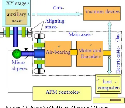
Figure 2 Schematic Of Micro-Operated Device
To translocate the point A, we interested to the specified location point B, first, suck the microsphere to the sucker on the main shaft and rotate the main shaft to ensure that area A may reach location C, then the auxiliary shaft will suck the microsphere and the main shaft will be separated from the microsphere, the microsphere will be rotated to point B with the auxiliary shaft. At last, the microsphere will be returned to main shaft and the rotation will be completed.
2.2 Introduction Of The Device.
The device is mainly composed of AFM system (Dimension 3100), precision main rotary shaft, auxiliary translocation shaft, X-Y micro displacement stage, motor control computer and negative pressure sucking device etc, as showed by Figure 2. Among which, the main shaft may rotate in low and stable speed at the driving of the DC torque motor, typically rotation speed is 1~3rpm. The auxiliary rotational shaft is provided with high-precision rolling bearing, and its angle accuracy is
higher than 1°. The precision alignment mechanism at the front parts of the main and auxiliary shaft can be aligned under the cooperation of AFM system to ensure the height variation of the surface within the span of AFM (about 5μm) when the microsphere is rotating at the circumference. The two-dimension displacement stage adopts the flexible hinge structure, the piezoelectric ceramic actuator will drive the auxiliary shaft to move relative to the main shaft, then the approach of the auxiliary shaft to and the separation of the main shaft from the microsphere will be completed. The negative pressure sucking gas circuit across the main shaft and the auxiliary shaft will be provided with negative pressure by the miniature vacuum pump, and the microsphere will be sucked onto the suction tube extending from the front end of the shaft.
2.3 Preparation Of Micro Suction Tube.
The device has very strict requirements for the micro suction tube used for sucking microsphere. On one hand, the inner holes of the suction tube shall be kept ventilating be free of dust to ensure that the microsphere will be sucked by the negative pressure gas circuit effectively; on the other hand, the tube shall be provided with a nozzle with a flat end surface and the inner holes, and outer surface close to the end surface shall be regular cone-shaped to ensure the locating accuracy of the translocation operation.
3. ANALYSIS OF THE TRANSLOCATION
ACCURACY
[image:2.612.92.298.298.475.2]perpendicularity requirements can also be met by adjusting the mutual vertical relation of the two shaft; the relative positions of the two shaft shall be constantly adjusted to locate the sphere during each rotational operation, therefore, it is necessary to analyze the impact of the relative positional relation of the two shaft (suction tube) on the rotational accuracy to improve the rotational accuracy of the microsphere[7].
Figure3 Diagram Of Transposition Error Analysis
See Figure 3 for the handover of the microsphere from the auxiliary shaft to the main shaft. Assume that the radius of the microsphere is R, the contact radius of the inner hole of the end surface of the suction tube is r, the coordinate origin of coordinate system is at point O (the axis direction of the auxiliary shaft in the Figure3 is perpendicular to the plane of the paper surface and is outward) the initial circle center of the microsphere is point O1; the axis
of the main shaft passes through point which is also the circle center of the microsphere after translocation, then the difference of the center heights of the two shaft is the projection of |O1 O|
on direction Z and will be marked as h; point S is the contact point of the sphere and the end surface of the suction tube and is also the fulcrum of the micro-displacement of the microsphere; ∠O SO1
is rotational angle of the microsphere and is marked as
α
; P1 is a point on the sphere before handover,and P2 is the point on the sphere after handover, w is marked as the horizontal distance between P1 and
P2. The coordinate of point S is (
2 2
R
−
r
, r). Assume that the coordinate of the initial spherical center O1 is (-yo1,h), point S is the common pointon the sphere before handover,
O S
1=
R
, solvethe equation, 2 2 2 2 2
o1
( y ) ( )
R = R −r + + −r h ,
then
2 2 2 2
1
(
)
o
y
=
R
− −
r
h
−
R
−
r
(1) Therefore,(
)
(
)
2 2 2 2 2 2 2
1 2
O O = R −r +rh− R − −r h R −r
In
∆
O OS
1 , use the cosine theorem, then we getthe rotational angle
α
.The point P1 and point P2 are actually a same
point on the sphere,
PS
1=
P S
2 , set P1 as (-yo1,h+R), and set the coordinate of point P2 as (-yp2,
zp2), then
2 2 2 2 2 2 2 2
1 2 2
2 2 2 2 2
(
o) (
)
(
p) (
p)
p p
R r
y
r h R
R r
y
r z
y
z
R
− +
+ − − =
− +
+ −
+ =
Solve the equation about yp2, get
2 2 2 2
2
(
)
p
r
r h
y
R
h r
R
r
R
R
−
=
− −
−
−
(2)Through the geometric relation and formulas 1 and 2, may get
w
=
y
p2−
y
o1 (3)Then, w is the error caused by the translocation of the difference h of the center heights.
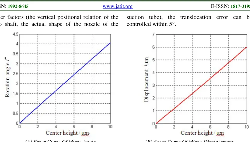
Assume that the diameter of the microsphere is 320μm and the inner diameter of the suction tube is 160μm, then the micro rotational angle
α
caused by the difference of the center heights from 0μm to 10μm and the micro-displacement curve w of the measuring point are showed in the following Fig. 4. As this figure shows, when the difference of the center heights of the main and auxiliary shaft is 10μ m, then one translocation will cause a rotational angle of about 4°; and the horizontal micro-displacement caused under this case is about 6μm.other factors (the vertical positional relation of the two shaft, the actual shape of the nozzle of the
suction tube), the translocation error can be controlled within 5°.
(A) Error Curve Of Micro Angle (B) Error Curve Of Micro-Displacement
Figure4 Error Of Altitudinal Centre Deviation Of Two Axis
4. TRANSLOCATION TEST
The test adopts the hollow plastic target microsphere with the diameter of about 320μm. The test procedure is as follows:
4.1 Preparation For Adjusting The Center
Suck the target microsphere onto the sucker and adjust roughly the center of the microsphere on the view field of AFM till the microsphere rotates
[image:4.612.102.519.71.308.2]constantly and maintains nearly the constant position of the highest point on the monitoring screen; then adjust finely the center. Because the measuring span of the AFM probe tip on direction Z is about 5 μm, the rotational eccentricity of the microsphere after center adjusting is less than 2 μm generally. The center adjusting of the auxiliary shaft is similar as that of the main shaft.
Figure 5 The CCD Monitor Image Of Microsphere Translocation Process
4.2 Translocation Test
The spatial locating test for the microsphere can be carried out after the above preparation for the test. Through the test, this paper completes the operation process of the locating principle specified in Fig. 1, see a)~c) in Fig. 5 for the specific demonstration order.
Select a mark on the surface of the microsphere. First, the microsphere will be sucked by the main shaft, start the main shaft translocation to rotate the mark on the surface of the microsphere to the
main shaft; start up the negative gas circuit of the main shaft and close the gas circuit of the auxiliary shaft, then the microsphere will be sucked on the main shaft and this translocation process will be completed.
Next we can estimate the accuracy. In this system, the CCD microscope image size is 1024 * 768, about 5 microns of macrostructure resolution. In such a system, the positioning of the operating microspheres error by pixel estimation, if the positioning displacement of a pixel, then corresponds to the actual angle error seen by the graph of Figure 4 which is less than 5 degrees.
Actually, through the devices mentioned by this paper, reversing the rotating of the shaft can also realize the traversal of all the orbits of the sphere surface, such as the equally spaced traversal across the circle, the traversal on three mutually perpendicular directions etc, and the measurement of the profile of the microsphere surface can be realized by coordinating the AFM system.
5. CONCLUSIONS
For the surface locating of the microsphere, this paper analyzes the locating principle of the main and auxiliary shaft; establish the device under the monitoring and cooperation of AFM system; analyze and derive the locating precision used by the main and auxiliary perpendicular shaft to translocate the microsphere, and the translocation error may up to 5°. Finally, conduct the sphere surface locating test with this system and verify the feasibility of this method. This device and method for locating the surface of the perpendicular shaft microsphere can be used to realize the measuring of the complete surface of the microsphere and micro processing. In further work we will use more precision CCD or use the AFM system directly to monitor the translocation process, in order to achieve higher translocation accuracy.
This work was supported by the National Natural Science Foundation of China (Grant No. 51005061) and the Doctoral Fund of Ministry of Education of China (Grant No. 20092302120006). The authors are pleased to acknowledge the contributions of Dr. Hu Zhenjiang and Cao Yongzhi at the Precision Engineering Research Institute of HIT and Dr. Li Bo, Meng Jie of the Research Center of Laser Fusion of CAEP.
REFERENCES
[1] D.M. Shi, W. S. Heng, F. Chen.A pellet sphericity measure system based on dual active contour models[C].Proceeding of the Second International Conference on Machine Learning and Cybernetics. 2003: 2781-2784.
[2] Q. K. Liang, D. Zhang, Z. Z. Chi, et.al. Six-dof micro-manipulator based on compliant parallel mechanism with integrated force sensor[J]. Robotics and computer Integrated manufacturing, 2011, 27(1):124-134.
[3] Y. T. Lee, Q.L. Nguyen, H. B. Huang, et.al. Increasing the throughput of phase-shifting dif-fraction interferometer for quantitative characterization of ICF ablator capsule surfaces. Fusion science and technology, 2009,55:405-410.
[4] X. S. Zhao, D. Z. Gao, X. J. Ma, et.al. Measure precision analysis of capsule vertical-AFM surface profiler system [J]. Atomic energy science and technology, 2012, 46(8):1014-1018. [5] S. Z. Wei, Z. S. Mao, M. D. Wang. A Study on 4π turning micro-size device for target pellet[J]. Journal of Zhejiang University(Engineering Science), 1997, 31(4): 409-414.
[6] M. Liu, G. Peng, X.H. Huang. Research on vacuum micro-tool for handling micro-target[J], Auto-Control,2002,21(4): 9-12.