International Journal of Emerging Technology and Advanced Engineering
Website: www.ijetae.com (ISSN 2250-2459, Volume 2, Issue 6, June 2012)211
Feed forward current regulator for low voltage ride through of
DFIG wind turbine
Prof. Prabhugaonkar
1, Prof. D.S. Bankar
2, Dr. D.B. Talange
31 Lecturer and M.Tech Student in Electrical Power Systems, Bharati Vidyapeeth Deemed University College of Engineering,
Pune
2 Ph.D. candidate at Bharati Vidyapeeth University, Currently working as Associate Professor in Electrical Engineering
Department of Bharati Vidyapeeth University College of Engineering, Pune
3 Ph. D IIT Bombay, Specialization in Systems and Control Engineering, currently working as Professor in Electrical
Engineering Department of Govt. College of Engineering, Pune
Abstract - A wind energy conversion system (WECS) differs from a conventional power system. The power output from a conventional power plant can be controlled while the power output of WECS depends on the wind. WECS are required to have active and reactive power control, frequency and voltage regulations and certain grid fault ride through capabilities. A successful low voltage ride through (LVRT) scheme is the main requirement for reliable and uninterrupted power generation for wind turbines equipped with doubly fed induction generators (DFIG). To enhance LVRT capacity a feed forward current control scheme is used for rotor side converter of DFIG. This conventional current regulator simulation analysis is performed using PID controllers in MATLAB.
Key Words - DFIG, LVRT, Voltage Dip , Feed forward , RSC , decoupled equations
I. INTRODUCTION
Due to extensive use of wind energy for power generation, wind plants are required to have grid ride through capabilities. [1]According to these
grid codes these plant are required to remain connected to the grid in the event of voltage dip at the high side of the wind plant step of transformer with a drop to 0.15 per unit (pu) for maximum of 0.625 seconds and also drop to 0 volts for maximum of 9 cycles.[2] The LVRT requirement is very important but it is difficult to satisfy for wind plants using DFIG system. This is because the stator of DFIG is directly connected to the grid and hence complete DFIG system is very much sensitive to grid disturbances.
II. DFIG SYSTEM
Doubly fed electric machines are electric motors or electric generators that have windings on both stationary and rotating parts, where both windings transfer significant power between shaft and electrical system.
Doubly fed machines are used in applications that require varying speed of the machine‟s shaft for a fixed power system frequency.
DFIGs are variable speed generators with advantages compared to other solutions. They are used more and more in wind turbine applications due to easy controllability, high energy efficiency and improved power quality. Fixed speed generators and induction generators had the disadvantages of having low power efficiencies at most speeds. To improve the efficiency, controlled power electronics converters are commonly used. Voltage source inverters are used to convert the voltage magnitude and frequency to match the grid values.
As power converters in a DFIG system only deal with rotor power, electronics costs are kept low, about approximately 20-25% of the total generator power. This is due to the fact that the rotor voltage is lower than the stator voltage. This implies that the converter is dimensioned to suit the rotor parameters. This makes the system more economical than using a full power rated converter in a series configuration.
International Journal of Emerging Technology and Advanced Engineering
Website: www.ijetae.com (ISSN 2250-2459, Volume 2, Issue 6, June 2012) [image:2.612.59.277.158.292.2]212
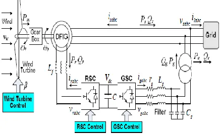
Figure 1 Basic DFIG Wind Turbine System
Wind turbine systems have two major control areas - electrical control of the converters & mechanical control of the blade pitch angle. In Implemented protective strategies are referred to as „fault ride through capability.‟
III. DFIG LVRT PROBLEM DESCRIPTION
The different types of faults that may affect a wind farm are mainly classified as symmetrical and non-symmetrical faults. Actual grid codes only specify symmetrical faults as they affect more severely the grid stability. On the other hand, non-symmetrical faults are more difficult to deal with DFIG. When voltage dip occurs is that the stator flux cannot follow the sudden change in stator voltage and a DC component in the stator flux appears and the stator flux vector becomes almost stationary. [3]The rotor keeps turning and high slip is generated, which tends to introduce over-voltage and over-current in the rotor circuits due to the effect of speed-voltage. Non-symmetrical faults create higher over-currents and over-voltages in the rotor because a negative sequence component exists in the stator voltage, and the slip of this negative sequence is very high.The excess current may damage the power converter, and the over-voltage may damage the rotor of the generator. Protection is required for power converter connected to the rotor from this over-voltage and over-current.
IV. MODELING OF DFIG & CONTROLLER
A reference frame is chosen to model the DFIG. The model of the induction machine is based on the fifth-order two axis representation commonly known as the “Park model.” A synchronously rotating reference frame is used with the direct –axis oriented along the stator flux position. In this way, decoupled control between the electrical torque and the rotor excitation current is obtained. The reference frame is rotating with the same speed as the stator voltage.
Generator convention are used, which means that the currents are outputs and that real power and reactive power have a positive sign when they are fed into the grid. Using the generator convention,
(1
(1)
(1)
With v being the voltage (V),R is the resistance[Ω], I is the current (A) ωs and ωr are the stator and rotor electrical angular velocity (rad/s) respectively and ψ is the flux linkage (Vs). The indices d and q indicate the direct and quadrature axis components of the reference frame and s and r indicate stator and rotor quantities respectively. All quantities in (1) are functions of time.
Due to the chosen orientation of the reference frame, the active and reactive power control are decoupled. The active and reactive power of the DFIG can be controlled by the q and the d-axis component of the rotor current, respectively. The voltage equations of the rotor are given in (1). Since for small values of Rs the stator flux is mainly determined by the stator voltage, it is practically constant. This implies that the derivative of the stator flux is close to zero and can be neglected . The rotor voltage equations of (1) can then be written as
(2)
The last term in both equations represents a cross-relation between the two current components. Reference voltages to obtain the desired currents can be written as
International Journal of Emerging Technology and Advanced Engineering
Website: www.ijetae.com (ISSN 2250-2459, Volume 2, Issue 6, June 2012)213
The idr and iqr errors are processed by a PI controller to give Vdr and Vqr, respectively. To ensure good tracking of these currents, the cross-related flux terms are added to Vdr and Vqr and to obtain the reference voltages.V. SURVEY OF DFIG FAULT RIDE THROUGH SOLUTIONS
The usual approach to the problem of voltage dips has been to place a crowbar circuit connected to the rotor of the wind turbine.[4][5] The crowbar short circuits the rotor when a voltage dip is detected and the power converter connected to the rotor is protected.
Crowbar circuits may be anti parallel thyristor crowbar, diode bridge crowbar or other more unusually configurations. The diode bridge crowbar is usually preferred to the anti parallel thyristor and the rest of configuration because it uses less thyristors and it is controlled more easily.
Another solution to LVRT is to connect an additional energy storage system (ESS)[6] or a dc chopper with a resistor across the dc bus of the power electronic converters. The ESS or dc chopper can balance the extra power that goes through the rotor circuit and prevent overvoltage at the dc bus. However, this solution requires an oversized RSC with a higher rating.
VI. CONVENTIONAL RSC CURRENT CONTROLLER
The conventional vector control scheme is commonly used to control the DFIG converters. It offers a good decoupled control of the active and reactive power for both the RSC and the GSC in the synchronous dq reference frame.[7]
The d–q convention used assumes that the q axis leads the d-axis by 90◦. The resulting block diagrams of
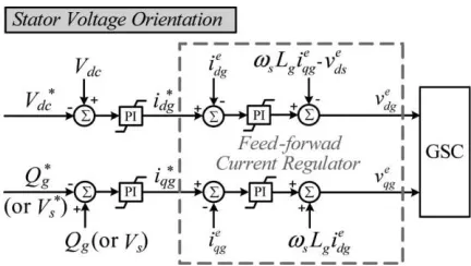
[image:3.612.338.551.146.273.2]the conventional vector control schemes for the RSC and the GSC are shown in Figs. 2 and 3, respectively. For the RSC the d-axis is oriented with the stator flux vector, and for GSC, the d-axis is oriented with the stator voltage space vector.
Fig. 2 Vector control scheme for the RSC with traditional FFCR.
Fig. 3 Vector control scheme for the GSC with traditional FFCR.
In the RSC vector control scheme, the electromagnetic torque (or stator output active power) only relates to the q -axis rotor current ie qr and the stator output reactive power only relates to the d-axis rotor current ie dr. This decoupled current control is commonly referred as the feed-forward current regulator (FFCR) [8]. The aforementioned FFCR scheme is derived from a steady state stator voltage and flux condition.
However, for a DFIG, the stator is exposed to grid disturbances and voltage sags, which may cause incorrect feed-forward compensation and result in unsatisfactory transient current regulation performance.
[image:3.612.336.552.298.420.2]International Journal of Emerging Technology and Advanced Engineering
Website: www.ijetae.com (ISSN 2250-2459, Volume 2, Issue 6, June 2012)214
vds = Rs ids + pλds – ωλqs λds = Ls ids + Lmidr vqs = Rs iqs + pλqs + ωλds λqs = Ls iqs + Lmiqr vdr = Rr idr + pλdr − (ω − ωr )λqr λdr = Lmids + Lr idr vqr = Rr iqr + pλqr + (ω − ωr )λdr λqr = Lmiqs + Lr iqr
(4)
Where all symbols have their usual meanings and ω is the rotating speed of the arbitrary reference frame. Equations (4) hold in both steady-state and transient conditions.
VII. MATLAB IMPLEMENTATION OF FEED FORWARD CURRENT REGULATOR
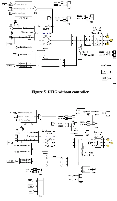
Fig. 4 shows a DFIG wind turbine system using MATLAB Simulink models.
Fig.5 shows the details of DFIG system without any controller while Fig.6 shows same DFIG system with controller.
The parameters of the DFIG Wind turbine used in simulation are as given below.
Wind turbine: rated speed 14 m/s , rated power 5.6 MW DFIG : MVA 3.6 ,rated stator voltage 4.16 kv , stator resistance 0.00706 pu , stator reactance 0.171 pu , rotor resistance 0.005 pu , rotor reactance 0.151 pu , mutual inductance 6 pu
[image:4.612.321.560.154.564.2]Figure 4 DFIG System Using MATLAB Simulink models
[image:4.612.55.283.457.600.2]Figure 5 DFIG without controller
International Journal of Emerging Technology and Advanced Engineering
Website: www.ijetae.com (ISSN 2250-2459, Volume 2, Issue 6, June 2012)215
[image:5.612.67.546.180.672.2]VIII. SIMULATION RESULTS
International Journal of Emerging Technology and Advanced Engineering
Website: www.ijetae.com (ISSN 2250-2459, Volume 2, Issue 6, June 2012) [image:6.612.79.549.150.662.2]216
International Journal of Emerging Technology and Advanced Engineering
Website: www.ijetae.com (ISSN 2250-2459, Volume 2, Issue 6, June 2012)217
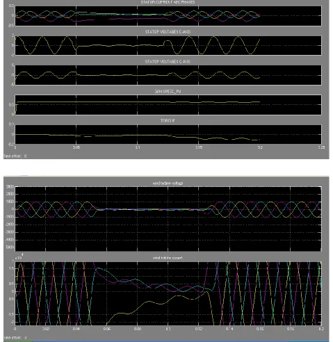
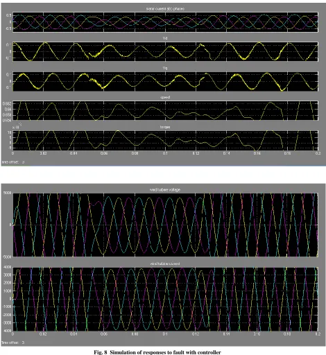
It is seen that when fault occurs, there are disturbances in stator current and stator voltage as shown in fig.7 when there is no controller. As against this , with controller , the disturbances in stator current and voltage are reduced as shown in fig.8.It is seen that the controller is able to reduce disturbances in all relevant parameters.
IX. CONCLUSION
Modern wind turbine plants are required to be stay connected to the grid under certain fault conditions. The LVRT is a challenging problem for wind power plants equipped with DFIGs to provide uninterrupted electric power.
Abrupt terminal voltage dips could induce a large transient current into the rotor circuit, which may damage the power electronic converters and result in disconnection of DFIG wind turbines from the power grid. This paper gives a brief overview on the existing LVRT solutions for DFIGs, and studies the effect of feed forward current regulator for the RSC to enhance the LVRT capability of DFIG wind turbines. The current regulator scheme is able to reduce the rotor transient current and disturbances in all relevant parameters. It helps DFIG wind turbines to remain in service and continuously supply active and reactive power to the power grid even during severe grid faults.
REFERENCES
[1 ] W. Qiao and R. G. Harley, “Grid connection requirements and solutions for DFIG wind turbines,” in Proc. IEEE Energy 2030 Conf., Atlanta, GA, Nov. 17–18, 2008, pp. 1–8.
[2 ] Federal Energy Regulatory Commission. (2005, Jun. 2). Regulatory Order No. 661: Interconnection for Wind Energy [Online].
Available:http://www.ferc.gov/industries/electric/indus-act/gi/wind.asp
[3 ] J. Lopez, P. Sanchis, X. Roboam, and L. Marroyo, “Dynamic behavior of the doubly fed induction generator during three-phase voltage dips,” IEEE Trans. Energy Convers., vol. 22, no. 3, pp. 709– 717, Sep. 2007.
[4 ] J. Morren and S. W. H. de Hann, “Ride through of wind turbines with doubly-fed induction generator during a voltage dip,” IEEE Trans. Energy Convers., vol. 20, no. 2, pp. 435–441, Jun. 2005. [5 ] I. Erlich, H. Wrede, and C. Feltes, “Dynamic behavior of
DFIG-based wind turbines during grid faults,” in Proc. Power Convers. Conf. (PCC 2007), Nagoya, Japan, Apr. 2–5, pp. 1195–1200. [6 ] C. Abbey and G. Joos, “Supercapacitor energy storage for wind
energy applications,” IEEE Trans. Ind. Appl., vol. 43, no. 3, pp. 769–776, May/Jun. 2007.
[7 ] W. Qiao,W. Zhou, J. M. Aller, and R. G. Harley, “Wind speed estimation based sensorless output maximization control for a wind turbine driving a DFIG,” IEEE Trans. Power Electron., vol. 23, no. 3, pp. 1156–1169, May 2008.