FUZZY ADAPTIVE PID CONTROL OF LARGE ERECTING
SYSTEM
LIANG LI,JIAN XIE, JIANZHAO HUANG
Xi’an Research Inst. Of Hi-Tech Hongqing Town, Xi’an 710025, Shanxi, China
ABSTRACT
In considering nonlinearity and uncertainty in the large erecting system, a fuzzy adaptive PID controller is introduced to improve the control performance. The mathematic model is constructed at first based on the physical laws. Then, the fuzzy logic algorithm which can regulate PID parameters on-line is designed and fuzzy inference rules are established between the PID parameters and the error and change in error. Step response and position tracking are implemented on this large erecting system. Simulation and experiment results demonstrate that the fuzzy adaptive PID controller has effectively improved the performance as compared with the conventional PID controller and fixed fuzzy controller. Further, the fuzzy adaptive PID controller is simple, easy to understand and realize.
Keywords: Fuzzy PID, Adaptive Control, Erecting System, Electro-Hydraulics
1. INTRODUCTION
Electro-hydraulic proportional systems have been frequently used in large erecting mechanism of many machineries and equipment, for example, the crane and some armaments. Because they provide many advantages compared to electric motors, including high power capability and mechanical efficiency, good positioning capability, and fast response characteristics. However, the hydraulic systems have many uncertainties, time varying and highly nonlinear characteristics due to the flow-pressure relationship, oil leakage, dead zone of valve, volume flow unbalance of asymmetrical cylinder, oil temperature variation and so on [1]. Furthermore, the large erecting systems are always subjected to large inertia variation, substantial external loads and various working environments. So using conventional control methods cannot guarantee our request for the large erecting system.
In order to solve such hydraulic erecting control problems some research efforts have been made in recent years. For example, C. L. Ma proposed intelligent integration controller in article [2], and C. Q. Yu applied non-linear predictive controller in reference [3]. These control methods provide satisfactory results from their simulation. However, all of them have not been down experiments. Further, when parameters of the plants or environments change, they cannot adaptively compensate these changes and always lead to instability. Fuzzy logic-based controller is an intelligent control method based on the fuzzy set theory which proposed by L. A. Zadeh in 1965. The
fuzzy controller imitates the humans thinking and needn’t to know the accurate mathematical model of the controlled object. It shows good results when applying to control the nonlinear systems. So in recent years, more and more research efforts about using fuzzy controller in hydraulic systems control have appeared [4-7]. But the design of fuzzy rules which is the centre of fuzzy control depends largely on the experience and knowledge of experts. There is no systematic method to design the number of rules and membership functions by now, and only the fuzzy logic control method may not guarantee satisfactory request. PID controller is a most widely used control method in industrial control, but it cannot regulate PID parameters under different conditions. Combining the two control methods that using fuzzy logic algorithm to regulate the PID parameters has proved to be a good solution, and many researchers have down contributory research. For example, Y. L. Sang proposed a fuzzy controller for an electro-hydraulic fin actuator using phase plane method [8], J. M. Zheng applied self-tuning fuzzy PID controller for a SRM direct drive volume control hydraulic press [9], and D. Edvard used fuzzy PID controller to electro-hydraulic servo control [10].
system in response to the nonlinearity. And the fuzzy adaptive PID control scheme performs more accurate response and better stability, as compared with the conventional PID control and fixed fuzzy control.
2. MATHEMATIC MODEL OF ERECTING SYSTEM
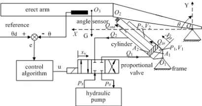
Fig.1 shows the schematic diagram of the erecting system, which is composed of a hydraulic pump, an electro-hydraulic proportional valve, an asymmetrical cylinder, large erect arm and angle sensor. One end of the cylinder O1 linked to the
frame and the other end O2 linked to the erect arm.
The cylinder can rotate around the two points O1
and O2. At the same time, the erect arm can rotate
around the point O which is the integration point of the erect arm and the frame. The angle of the erect arm is controlled as follows: Once the voltage input corresponding to the desired angle θd is transmitted to the controller, the input current is generated in proportion to the error e between the input and the output from the angle sensor which is applied to measure the erect angle θ of the erect arm. Then, the valve spool position and direction are controlled according to the input current. Depending on the spool position, the flows as well as the direction supplied to each cylinder chamber is determined. The motion of the erect arm actuated by the cylinder is then controlled by these flows.
Figure 1: The Schematic Diagram Of Erecting System
2.1 Kinematic and Dynamic of Erecting System In Fig.1 PS is the hydraulic supply pressure and P0 is the reservoir pressure, P1 and P2 are the fluid
pressure on the two cylinder sides. xv is the spool
valve displacement, θ is the erect angle, XP is the piston displacement, O3 is the erect arm center of
gravity. Let OO1=l1, OO2=l2, O1O2=l3, OO3=l4, ∠O1OO2=θ0, ∠OO2O1=α, ∠XOO3=γ. Kinematic
model of the erect system can be written as
2 2
1 2 21 2cos( 0) 3
P
X = l +l − l l θ θ+ −l (1) And based on the rotation differential equation of the erect arm, the dynamics model can be derived.
1sin 4cos( )
Jθ=Fl α−Gl γ θ+ (2) where F represents the output force from the cylinder, J is the erect arm moment of inertia and G is its gravity. In the triangle OO1O2, applying law
of sines we can receive the equation
3 1
0
sin sin( )
P
l X
l
α θ θ
+ =
+ (3)
So from the equations (2) and (3), we have
4 1 0 3
cos( ) sin( ) / ( P)
J Gl
F
l l X
θ γ θ
θ θ + + = + + (4)
2.2 Mathematic Model of Hydraulic System We assume that the flow areas to the supply and return port of the valve be proportional to the spool displacement xv. Then the flow of oil across the
spool valve can be given as:
1 1
1
1
2
sgn( ) 0
2
0
d v S S v
v
d v
C wx P P P P x
Q
x
C wx P
ρ ρ − − ≥ = < (5) 2 2 2 2 2 0 2 0 sgn( )
d v v
v
d v S S
C wx P x
Q
x
C wx P P P P
ρ ρ ≥ =
− − − <
(6
) where Cd is the discharge coefficient, w is the spool valve area gradient, ρ is the oil mass density, and the following function sgn(x) is used
1 0
sgn( ) 0 0
1 0 x x x x > = = − <
(7)
Applying the continuity equation to the fluid flowing in each chamber of the cylinder, the following two expressions can be derived.
1 1 1 1 ( 1 2)
P in
dX V dP
Q A C P P
dt β dt
= + − + (8)
2 2 2 2 ( 1 2) 2
P
in out
dX V dP
Q A C P P C P
dt β dt
= + − − − (9)
where Cin is the inwards leakage coefficient of cylinder, Cout is the outwards leakage coefficient of cylinder, β is the fluid bulk modulus, V1=V10+A1XP
and V2= V20+A2(l-XP) are the total fluid volumes in
[image:2.612.93.298.452.560.2]Based on the Newton’s law of motion, the force balance equation of the cylinder can be obtained as follows:
2
1 1 2 2 2 ( )
P P
L
d X dX
m P A P A B F
dt
dt = − − − (10)
where m represents the equivalent mass of the cylinder, B is the equivalent viscous damping coefficient, FL is the external force come from the erect arm and it is equal to the F in the equation (4).
The spool valve dynamics is always approximate to a linear second order differential equation:
2
2 2 2
( ) ( )
2 ( )
v v
n d n v n
d x t dx t
w B w x w u t
dt
dt + + = (11)
where wn represents the natural frequency and Bd is the damping factor.
3. FUZZY ADAPTIVE PID CONTROLLER DESIGN
3.1 Structure and Principle of Fuzzy Adaptive PID Controller
The erecting system is a complicated nonlinear system as introduced in section 1. Applying the conventional PID controller is difficult to achieve high control precision and good performance due to the influences of the nonlinear and uncertain factors existed in the erecting system. Meanwhile, it is poor in turning parameters in different conditions. For these reasons, the fuzzy adaptive PID control technique is introduced to overcome the above problems in this paper.
The fuzzy adaptive PID controller is combined the conventional PID with the fuzzy logic algorithm to improve the performance of the erecting system. Its principle is shown in Fig.2. The fuzzy logic algorithm has two inputs error e and change in error
[image:3.612.327.518.325.506.2]ec, and three outputs ∆Kp, ∆Kiand ∆Kd which are the change in parameters Kp, Ki and Kd of the PID controller. And it composed of three main elements: fuzzification, fuzzy inference and defuzzification.
Figure 2: Structure Of The Fuzzy Adaptive PID Controller
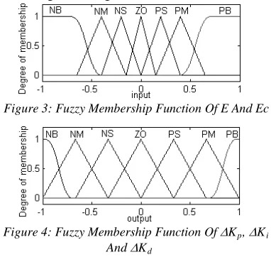
3.2 Fuzzification of Input and Output Variables The first step is fuzzification of the input and output variables, which transforms the input and output data into semantic value. In this paper, the fuzzy range of the variables are e,ec∈ [-3, 3], ∆Kp
∈ [-1, 1] ∆Ki∈ [-0.2, 0.2]and ∆Kd ∈ [-0.05, 0.05]. And they all transformed into uniform fuzzy range [-1 1]. Then, the fuzzy range is separated into 7 semantic variables, and the corresponding fuzzy subsets are e, ec, ∆Kp, ∆Ki, ∆Kd=[NB, NM, NS,
ZO, PS, PM, PB], where NB is negative big; NM is
negative middle; NS is negative small; ZO is zero;
PS is positive small; PM is positive middle; PB is positive big. Let NB be Z-shaped membership function ‘zmf’, PB is Sigmiod membership function ‘smf’ and others are triangular membership function ‘trimf’. From the membership function, the degree of membership of all the fuzzy subsets can be derived. All the fuzzy member functions are shown in Fig.3 and Fig.4.
Figure 3: Fuzzy Membership Function Of E And Ec
Figure 4: Fuzzy Membership Function Of ∆Kp, ∆Ki
And ∆Kd
3.3 Fuzzy Inference and Defuzzification
The most important step is establishment of fuzzy inference rule between the input variables
[image:3.612.90.298.470.690.2]Table 1: Fuzzy Rule
NB NM NS ZO PS PM PB
NB PB/NB/PS PB/NB/NS PM/NM/NB PM/NM/NB PS/NS/NB ZO/ZO/NM ZO/ZO/PS
NM PB/NB/PS PB/NB/NS PM/NM/NB PS/NS/NM PS/NS/NM ZO/ZO/NS NS/ZO/ZO
NS PM/NB/ZO PM/NM/NS PM/NS/NM PS/NS/NM ZO/ZO/NS NS/PS/NS NS/PS/ZO
ZO PM/NM/ZO PM/NM/NS PS/NS/NS ZO/ZO/NS NS/PS/NS NM/PM/NS NM/PM/ZO
PS PS/NM/ZO PS/NS/ZO ZO/ZO/ZO NS/PS/ZO NS/PS/ZO NM/PM/ZO NM/PB/ZO
PM PS/ZO/PB ZO/ZO/NS NS/PS/PS NM/PS/PS NM/PM/PS NM/PB/PS NB/PB/PB
PB ZO/ZO/PB ZO/ZO/PM NM/PM/PM NM/PM/PM NM/PM/PS NB/PB/PS NB/PB/PB
There are 49 rules in Table 1, and the implication used in the rules is as follows:
If e is Ai and ec is Bj, then ∆Kp/∆Ki /∆Kd is
Cij/Dij/Eij where Ai, Bj, Cij, Dij, Eij are corresponding to the fuzzy subsets of e, ec, ∆Kp,
∆Ki , ∆Kd. The Mamdani’s Min-Max operator is adopted to carry out fuzzy inference. For example, the degree of membership of the fuzzy subsets Cij for the parameter ∆Kp can be derived.
7
'( ) , 1{[ ( ) ( )] ( )}
C p i j i j Cij p
u K u e u ec u K
=
∆ = ∨ ∧ ∧ ∆ (12)
where u(x) is the degree of membership.
Defuzzification is the process of converting fuzzy variables to crisp values. The center of gravity method is applied to obtain the crisp values. The parameter ∆Kp (∆Ki and ∆Kd.are similar) can be calculated from the following equation.
7
' 1
7 ' 1
( )
( , )
( )
p C p
k p
C p
k
K u K
K e ec
u K
=
=
∆ ∆
∆ =
∆
∑
∑
(13)After defuzzification, the three parameters Kp, Ki and Kd can be obtained as follows:
Kp=Kp0+∆Kp
Ki=Ki0+∆Ki
Kd=Kd0+∆Kd
where Kp0, Ki0and Kd0 are the original parameters of the PID controller.
4. SIMULATION AND EXPERIMENTAL RESULTS
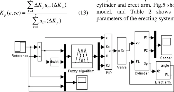
[image:4.612.148.446.463.621.2]In order to demonstrate the performance of the fuzzy adaptive PID controller, some of simulations and experiments are implemented on the erecting system under different conditions. The simulation model is built in versatile software Matlab/Simulink using the derived equations in section 2. It composed of four parts: controller, spool valve, cylinder and erect arm. Fig.5 shows this simulation model, and Table 2 shows the characteristic parameters of the erecting system.
Figure 5: Simulink Block Diagram Of The Erecting System Model
e
ec
ΔKp/
ΔKi/
Table 2: The Characteristic Values Of The Erecting System
Parameters Symbols Values Units
Supply pressure PS 18 MPa
Discharge coefficient of the spool valve Cd 0.62 —
Area gradient of the spool valve w 2.51×10⁻² m
Bulk modulus of oil β 7.5×10⁸ Pa
Length of piston head l 1.5935 m
Equivalent viscous damping coefficient B 800 N/m/s
Mass density of oil ρ 868 Kg/m3
Equivalent mass of the piston m 178.31 Kg
Inwards leakage coefficient of cylinder Cin 2.41×10⁻¹¹ m3/s*Pa
Outwards leakage coefficient of cylinder Cout 7.1×10⁻¹³ m3/s*Pa
Equivalent mass of the erect arm M 1155.98 Kg
Moment of inertia of the erect arm J 10023 Kg*m2
Section area of piston-side/rod-side A1/A2 0.0175/0.0133 m2
Dead volume of piston-side/rod-side V10/V20 1.7×10⁻⁵/1.3×10-5 m3
Length of OO1/OO2/O1O2/OO3 l1/l2/l3/l4 1.132/1.62/1.032/3.5 m
Angle of ∠O1OO2/ ∠XOO3 θ0/γ 0.6816/0.1047 rad
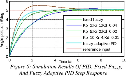
The step response simulation results of PID, fixed fuzzy and fuzzy adaptive PID are shown in Fig.6, and the step value is 5 degree. It can be seen that the step response speed of fixed fuzzy controller is slow, and it has vibration when reach the step value. The PID controller has higher response speed as increase of the Kp, Ki and decrease of Kd, but overshoot and more adjusting time will happen. However, the fuzzy adaptive PID controller shows fast response speed, accurate steady-state precision and short adjusting time. Because this method can regulate the PID controller parameters adaptively according to the error e and change in error ce.
0 2 4 6 8 10
0 1 2 3 4 5 6
Time t/s
Angl
e
pos
ition
θ/
deg fixed fuzzy
[image:5.612.92.297.460.586.2]Kp=2;Ki=1;Kd=0.04 Kp=5;Ki=2;Kd=0.02 Kp=10;Ki=4;Kd=0.01 fuzzy adaptive PID reference input
Figure 6: Simulation Results Of PID, Fixed Fuzzy, And Fuzzy Adaptive PID Step Response
Fig.7 shows the step response experimental results of the three controllers under same condition. We can see that the experimental results are similar to the simulation results in general and the fuzzy adaptive PID controller is also the best controller among the three controllers. Compared to the simulation, the curves are not smooth and much straighter. And it has about 1.23s lag time in real erecting system, for example, the steady-state response time is 4.62s for fuzzy adaptive PID controller in experiment, but just 3.37s in simulation.
0 2 4 6 8 10
0 1 2 3 4 5
Time t/s
Angl
e
pos
ition
θ/
deg
Figure 7: Experiment Results Of PID, Fixed Fuzzy, And Fuzzy Adaptive PID Step Response
In order to demonstrate the tracking ability of fuzzy adaptive PID controller, the tracking simulation and experiment are designed. The tracking objective is an angular displacement curve from 0° to 90° as shown in Fig.8 (a) (the red), and its angular velocity obey to the curve shown in Fig.8 (c) (the red). Applying the PID, fixed fuzzy and fuzzy adaptive PID to track the angular displacement curve, the simulation and experiment results are shown in Fig.8 and Fig.9, respectively.
shown in Fig.8 (c) and Fig.9 (c). The angular velocity curve of fuzzy adaptive PID controller is steadier than conventional PID controller and fixed fuzzy controller. For example, the max error is 1.54deg/s in the experiment, but 1.84deg/s for PID and 1.97deg/s for fixed fuzzy.
0 10 20 30 40 50 60 70
0 20 40 60 80
Time t/s
D
is
pl
ac
em
ent
θ/
deg
2 4 6 8
0 2 4 fixed fuzzy
PID
fuaay adaptive PID reference input
(A) Angular Displacement
0 10 20 30 40 50 60 70
-1 -0.5 0 0.5 1 1.5 2
Time t/s
Er
ror
θ/
deg
(B) Tracking Error
10 20 30 40 50 60 70
0 0.5 1 1.5
Time t/s
V
el
oc
it
y
v
/(
deg/
s
)
[image:6.612.317.520.74.347.2](C) Angular Velocity
Figure 8: Simulation Results Of PID, Fixed Fuzzy, And Fuzzy Adaptive PID Tracking Control
0 10 20 30 40 50 60 70
0 20 40 60 80
Time t/s
D
is
pl
ac
em
ent
θ/
deg
2 4 6 8
1 2 3 4 5
(A) Angular Displacement
0 10 20 30 40 50 60 70
-1 -0.5 0 0.5 1 1.5 2
Time t/s
E
rr
or
e/
deg
(B) Tracking Error
0 10 20 30 40 50 60 70
0 0.5 1 1.5 2
Time t/s
V
el
oc
ity
v
/(
deg/
s
)
(C) Angular Velocity
Figure 9: Experiment Results Of PID, Fixed Fuzzy, And Fuzzy Adaptive PID Tracking Control
All the simulations and experiments demonstrate that the fuzzy adaptive PID controller can obviously improve the response speed and control precision, and it presents satisfactory performance for the large erecting system.
5. CONCLUSION
[image:6.612.92.296.160.516.2]REFERENCES:
[1] Q. H. Gao, “Study on electro hydraulic proportion control in large-sized mechanism erecting process”, Chinese Journal of
Mechanical Engineering, Vol. 40, No. 2, 2004,
pp. 89-192.
[2] C. L. Ma, X. X. Huang, F. Li, “Simulation study of intelligent control for large mechanism erection system”, Acta ArmamentarⅡ, Vol. 29, No. 2, 2008, pp. 227-231.
[3] C. Q. Yu, X. S. Guo, C. L. Ma, “Nonlinear predictive control in the process of missile erecting”, Acta ArmamentarⅡ, Vol. 29, No. 11, 2008, pp. 1400-1404.
[4] G. P. Liu, S. Daley, “Optimal-turning PID control for industrial systems”, Control
Engineering Practice, No. 9, 2001, pp.
1185-1194.
[5] A. S. Garett, E. B. James, “Experiments and simulations on the nonlinear control of a hydraulic servo-system”, IEEE transactions on
control systems technology, Vol. 7, No. 2, 1999,
pp. 238-247.
[6] B. Šulc, J. A. Jan, “Nonlinear modeling and control of hydraulic actuators”, Acta
Polytechnica, No. 42, 2002, pp. 41-47.
[7] Zulfatman, M. F. Rahmat, “Application of self-tuning fuzzy PID controller on industrial hydraulic actuator using system identification approach”, International Journal on Smart
Sensing and Intelligent Systems, Vol. 2, No. 2,
2009, pp. 246-261.
[8] Y. L. Sang, S. C. Hyung, “A fuzzy controller for an electro-hydraulic fin actuator using phase plane method”, Control Engineering Practice, No.11, 2003, pp. 697-708.
[9] J. M. Zheng, , S. D. Zhao, S. G. Wei, “Application of self-tuning fuzzy PID controller for a SRM direct drive volume control hydraulic press”, Control Engineering Practice, No. 17, 2009, pp. 1398-1404.