International Journal of Emerging Technology and Advanced Engineering
Website: www.ijetae.com (ISSN 2250-2459,ISO 9001:2008 Certified Journal, Volume 4, Issue 5, May 2014)
887
Comparative Analysis of Direct Torque Control and Flux
Control of Induction Motor Using P and PI Controller
Jyotsna Mehra
1, Puneet Sharma
2, Chhaya Dubey
3M.Tech (PSE), Galgotias University, Greater Noida, India
Abstract— This paper presents a direct torque control (DTC) of three phase induction motor drive (IMD) using P and PI controller for speed regulation and low torque ripples. DTC is used in variable frequency drives to control the torque of three phase AC electric motors .DTC is the excellent control strategy of stator flux and torque ripples of IMD. The DTC method is optimized by using P and PI controller in the speed regulating loop of IMD.
The performance and effectiveness of DTC of IMD by using P and PI controller has been studied and analysed by MATLAB/SIMULINK.
Keywords—Direct Torque Control (DTC), P controller, PI controller, Induction Motor Drive (IMD).
I. INTRODUCTION
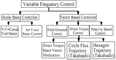
Three phase induction motor is most widely used and popular ac motor used for industrial drives since it is cheap, efficient and reliable. The main advantage is that induction motors do not require any electrical connection between stationary and rotating parts of the motor. Therefore, i t d o e s n o t r e q u i r e any mechanical commutator (brushes), leading to the fact that maintenance is not required. Induction motors has lower weight and inertia, efficiency and overload capability is high [1]. Generally two control methods are used for controlling IMD, first is scalar control and other one is vector control. The scalar control is operating in steady state and controls the angular speed of current, voltage and flux linkage in space vectors. It does not operate in the transient state. Vector control is used for controlling not only angular speed and magnitude but also for controlling the instantaneous position of voltage, current and flux linkage of space vector. Due to several advantages of vector control method over scalar control methods, we are considering vector control method. Vector control method is further classified as Field Oriented Control (FOC) and Direct Torque Control (DTC). A simple method of speed controls DTC for induction motor drive is compared with FOC, because FOC methods are complex and sensitive to inaccuracy in motor parameter values [2]. The main features of DTC includes direct control of flux and torque, indirect control of stator current and voltages and high dynamic performance even at stand still condition.
These benefits of DTC makes it superior from all other control methods such as co-ordinate transformation is not required in DTC, torque response time is minimum, PWM is not needed, switching losses and complexity is lower.
[image:1.612.327.563.437.559.2]Some of the drawbacks of DTC are, variable switching frequency, torque and flux ripples are high, starting problem and operating conditions of speed are lower, flux and current distortion are caused by stator flux vector changing with the sector position, and the speed of IMD is changing with transient and dynamic state operating condition [3]. In order to overcome with these difficulties, the proposed DTC with P and PI controller is used. Finally the effectiveness, validity, and performance of DTC of IMD using both P and PI controllers is analyzed, studied, and confirmed by simulation results and the results shows that low stator flux and torque ripples are obtained, and good speed regulator of IMD with the proposed technique using MATLAB/SIMULINK.
Fig 1: Classification of Induction Motor Control Methods.
II. DYNAMIC MODELLING OF INDUCTION MOTOR
International Journal of Emerging Technology and Advanced Engineering
Website: www.ijetae.com (ISSN 2250-2459,ISO 9001:2008 Certified Journal, Volume 4, Issue 5, May 2014)
888 (i)With respect to stator [11]
( )
( )
/
(
( ))
( )
( )
/
(
( ))
( )
( )
/
(
( ))
sa s sa sa
sb s sb sb
sc s sc sc
V
t
R i
t
d dt
t
V
t
R i
t
d dt
t
V t
R i
t
d dt
t
(1)
(ii)With respect to rotor [11]
( )
( )
/
(
( ))
( )
( )
/
(
( ))
( )
( )
/
(
( ))
ra r ra ra
rb r rb rb
rc r rc rc
V
t
R i
t
d dt
t
V
t
R i
t
d dt
t
V t
R i
t
d dt
t
(2)
Converting to dq frame: The three-phase to two-axis voltage transformation is achieved using the following
equations. Where Vsa, Vsb and Vsc are the three-phase
stator voltages, while and, Vsd and Vsq are the two-axis
components of the stator voltage vector Vs.
i
sa,
i
sb,
i
sc And,
,
ra rb rc
i
i
i
are three phase stator and rotor currentsrespectively, while
i
sd,
i
sqandi
rd,
i
rqare two phase stator currents and rotor currents respectively.[6][11].cos
cos(
2 / 3)
cos(
2 / 3)
2 / 3
sin
sin(
2 / 3)
sin(
2 / 3)
sa sd sb sq sc
V
V
V
V
V
(3) (iii) Flux Equations [11]
1 /
1 /
1 /
1 /
sd sd sd s
sq sq sq s
rd rq rd r
rq rd rd r
V
i R
s
V
i R
s
i R
s
i R
s
(4)(iv) Stator Current Equations [11]
(
/
)
(
/
)
(
/
)
(
/
)
sd sd r x rd m x
sq sq r x rq m x
i
L
L
L
L
i
L
L
L
L
(5)
(v) Rotor Current Equations [11]
(
/
)
(
/
)
(
/
)
(
/
)
rd rd s x sd m x
rq rq s x sq m x
i
L
L
L
L
i
L
L
L
L
(6)
Where [11]
2 x s r m
L
L L
L
(7)
III. DIRECT TORQUE CONTROL (DTC)
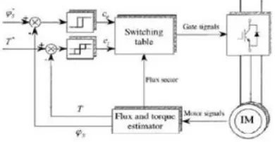
DTC is a technique used in variable frequency drive for controlling the torque and finally the speed of three phase AC motor drive. It includescalculation of an estimate of the motor's magnetic flux and torque based on the measured voltage and current of the motor [3][11].
By integrating the stator voltages the stator flux linkage is estimated. Torque is estimated by the cross product of estimated stator flux linkagevector and measured motor currentvector. The estimated torque and flux magnitude are compared with the reference values. If the estimated flux or torque changes from the reference greater than allowed limit, the variable frequency drive transistors are turned off and on in such a way that the flux and torque errors will return in its tolerance bands as fast as possible.
DTC of ac drives depends on stator voltage control; hysteresis torque and flux controllers determine the errors which govern the selection of the needed voltage space vectors to be applied to the motor. A switching logic is applied either to increase or decrease the flux, and increase or decrease the torque, or effect no changes [7].
DTC has a simple control scheme and also very less computational requirement, such as current control, rotor position measurement, PWM control and co-ordinate transformation is not required. The main feature of DTC is simple control scheme, good dynamic behaviour, decoupled control of torque and flux, absence of mechanical transducers, reduced parameter sensitivity, high performance and efficiency.
International Journal of Emerging Technology and Advanced Engineering
Website: www.ijetae.com (ISSN 2250-2459,ISO 9001:2008 Certified Journal, Volume 4, Issue 5, May 2014)
889 In a DC motor by passing current through the field winding in the stator, magnetic field is created. The magnetic field created is always at right angles to the field created by the armature winding. This condition, known as field orientation, is required for generating maximum torque. When the field orientation is attained, the DC motors torque is controlled easily by changing the armature current and by constant maintaining of the magnetising current. In direct torque control method the stator flux and stator torque is controlled directly by appropriate selection of inverter switching state[11].
Fig 2: Block Diagram of Direct Torque Control
IV. SPEED CONTROLLER
The SIMULINK toolbox of the MATLAB software is used for realising the speed controller model. The input to the speed controller block is the difference of the reference speed and actual speed. The speed controller output is limited to a proper value according to the motor rating to generate the reference torque. The speed controllers described in this study are P controller and PI controller.
(A) P CONTROLLER:
Basically P controller is used to decrease the steady state error of the system. The steady state error of the system decreases with the increase of the proportional gain factor
K
p. Despite of the reduction of steady state error of the system, P control can never manage to eliminate it.P controller can be used only when our system can tolerate a constant steady state error. Applying P controller decreases the rise time and after a certain value of
reduction on steady state error, increasing
K
p only leads to overshoot of the system response.(B) PI CONTROLLER:
The Proportional plus Integral Controller (PI) is widely used in industrial applications. The output of PI controller can be defined by following equation in time domain-
0
( )
( )
( )
t
c p i
V t
K t
K e t dt
(8)Where
V t
c( )
is the output of PI controller,K
p is theproportional gain,
K
i is the integral gain and e (t) is the instantaneous error signal. The combination of proportional and integral terms is important to increase the speed of response and also to eliminate the steady state error resulted from P controller. It is generally used in the areas where speed of the system is not an issue [9]. [image:3.612.77.272.270.371.2]The serious drawback of integral controller is that if the error does not change its direction then Integral controller gets saturated after a short period of time. To avoid this phenomenon we make use of limiter in the integral part of the controller before adding its output to the output of proportional controller.
Fig 3: Block Diagram of PI controller
V. SIMULATION RESULTS
[image:3.612.330.555.353.436.2]The SIMULINK block diagram of direct torque control of IMD using P and PI controller is shown in figure 3,
Table 1
Parameters and Values of IMD
PARAMETERS NOMINAL VALUE
Stator Resistance(Rs) 1.77 ohm
Rotor Resistance(Rr) 1.34 ohm
Mutual Inductance(Lm) 369e-3
Stator Inductance(Ls) 13.93e-3
Rotor Inductance(Lr) 12.12e-3
Inertia(J) 0.025Kgm^2
International Journal of Emerging Technology and Advanced Engineering
Website: www.ijetae.com (ISSN 2250-2459,ISO 9001:2008 Certified Journal, Volume 4, Issue 5, May 2014)
[image:4.612.48.296.112.297.2]890 Fig 4: DTC of IMD using P and PI Controller
[image:4.612.343.544.147.319.2]The simulation results of proposed DTC with both P controller and PI controller is shown in Figure 5 to Figure 10
[image:4.612.325.564.342.600.2]Fig 5: Speed Response using P controller
Fig 6: Torque Response using P controller
[image:4.612.65.268.360.517.2]International Journal of Emerging Technology and Advanced Engineering
Website: www.ijetae.com (ISSN 2250-2459,ISO 9001:2008 Certified Journal, Volume 4, Issue 5, May 2014)
[image:5.612.325.564.135.452.2]891 Fig 8: Speed Response using PI controller
Fig 9: Torque Response using PI controller
[image:5.612.73.265.145.466.2]International Journal of Emerging Technology and Advanced Engineering
Website: www.ijetae.com (ISSN 2250-2459,ISO 9001:2008 Certified Journal, Volume 4, Issue 5, May 2014)
892
VI. CONCLUSION
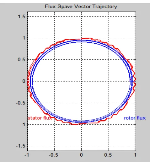
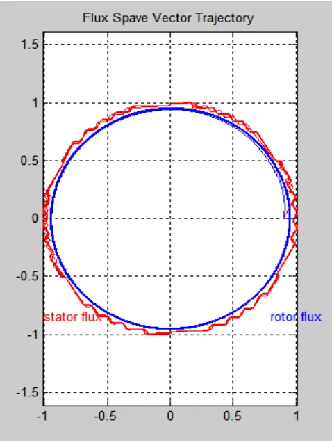
In this paper the direct torque control of IMD using P and PI controller has been presented. It has been observed by comparing the torque, speed and stator flux characteristics of PI and P controller that the stator flux is reduced in PI controller and torque ripples are also reduced by using PI controller as compared with P controller. But due to the property of overshooting of PI controller small disturbance is observed in the starting of speed and torque and afterwards the required speed and torque is obtained. So it can be concluded from the results that stator flux and torque ripples are reduced more by using PI controller as compared with the P controller. The two independent torque and flux hysteresis band controllers are used for controlling the torque and flux.
REFERENCES
[1] G.S. Buja, M.P.Kazmierkowski, ―DTC of pwm inverter-fed AC motors – A Survey‖, IEEE Trans. on Ind. Elec., volume 54, no. 4, 2004.
[2] I. Takahashi and Y. Ohmori, ―High-performance direct torque control of induction motor‖, IEEE Trans. Ind. Appl., vol. 25, no. 2, pp. 257-264, 1989.
[3] M. Dependrock, ―Direct self control (DSC) of inverter-fed induction Machine‖, IEEE Trans. on Power Electronics, volume 22, no. 5, pp. 820-827, September/October 1986.
[4] K.L.Shi, T.F.Chan, Y.K.Wong and S.L.Ho,‖ Modelling and Simulation of The Three Phase induction Motor using Simulink‖ Int. J. Elect. Engg. Educ., Vol. 36, pp. 163–172. Manchester U.P., 1999. [5] Dal Y Ohm, ―Dynamic Modelling of Induction Motor for Vector Control", IEEE Transactions on Power Delivery, vol.14, no.2, October 2008.
[6] I. Takahashi and T.Noguchi, ―A new quick response and high efficiency control strategy of an induction motor‖, IEEE Trans. Ind. Appl., vol. 22, no. 5, pp. 820-827, 1986.
[7] Zuraida Binti Zainol, ―Development of simulink model of DTC of induction motor", IEEE Transactions on Power Delivery, vol.14, no.2, October 2005.
[8] Tang L., Zhong L., Rahman M.F., Hu Y., ―A novel direct torque controlled interior permanent magnet synchronous machine drive with low ripple in flux and torque and fixed switching frequency‖, IEEE Transactions on Power Electronics, 19(2), p.346-354, 2004. [9] Yukinoi Inour, Shigro Morimoto, Masayuki Sanada, ―Control
Method Suitable for DTC Based Motor Drive System Satisfying Voltage and Current", IEEE Transactions on Power Delivery, vol.14, no.2, October 2012.
[10] Wu Tao,Zhau Liang, ―Simulation Of Vector Control Frequency Converter Of Induction Motor Based On MATLAB/simulink", IEEE Transactions On Industrial Applications, vol. 16, no.2, December 2011.