Efficient Rectangular to Polar Conversion for Multiband
and Multimode Wireless Communications
Anurag Vijay Agrawal
M.E. Scholar
Department of Electronics and Comm. Engg. NITTTR, Sector-26, Chandigarh (India)
Rajesh Mehra
Associate Professor
Department of Electronics and Comm. Engg. NITTTR, Sector-26, Chandigarh (India)
ABSTRACT
The necessity of high data rates wireless communication becomes important for the end-user, especially to support high mobility lifestyle ”always get connected”, and demand for the multimedia communication, such as the video phone, live streaming, online gaming, and the Internet. Since wireless communication systems need to deal with multiband and multimode operations on complex signals many-a-times, the efficient phase and magnitude extraction is always needed. This paper presents an architecture for the efficient rectangular to polar conversion (RPC) for these multiband and multimode wireless communications using fully parallel CORDIC, a Linear Convergence Algorithm. The architecture was synthesized with ISE 10.1 software and was implemented in a Xilinx FPGA device achieving better performance than the previous LUT-based approaches.
General Terms
Current wireless communication systems require a multi-band/multi-standard approach, so that several communication standards can be incorporated in one device to satisfy the users who expect mobility, ubiquitous connection and high data rates at the same time. Instead of including an independent architecture for each standard, universal transmitter architecture capable of generating all the different standards waveforms seems to be the best solution. Also the rapid evolution of the communication systems has created new demands on multimode systems that support various modulation formats such as Quadrature Amplitude Modulation (QAM) for 3G system, and Orthogonal Frequency Data Multiplex Modulation (OFDM) for 4G and DVB-T/H systems. An efficient rectangular to polar conversion is required so that transmitters must accommodate constant envelop signals as well as non-constant envelop signals to achieve multimode and multiband operations.
Keywords
RPC, polar transmitter, CORDIC, coordinate conversion, atan2, FPGA.
1.
INTRODUCTION
Wireless communications systems including cellular communications, personal area networks (PANs), local area networks (LANs) and metropolitan area networks (MAN) have presented a considerable development in recent years and keep evolving constantly [1]. These requirements put great challenges as traditional analog inphase/quadrature (I/Q) radio architectures are not well suited to multiband and multimode operation due to their
band-specific nature. Baseband mixing produces unwanted spurious products requiring use of surface acoustic wave (SAW) bandpass filters to reject these adverse signals and minimize wideband noise [2]. The use of bandpass filters forces designers to diplex the signal path or build individual transmitter chains for each band of interest. This design requires additional circuitry in order to achieve multiband operation; whereas in order to achieve multimode operation, analog transmitter architectures must be able to accommodate constant envelope signals (phase and frequency modulations), as well as non-constant envelope signals (amplitude modulated) simultaneously. To avoid distortion of non-constant envelopes, analog transmitters must employ linear (class A) amplifiers or use predistortion techniques to linearize slightly saturated (class A/B) amplifiers [3]. Both of these implementations sacrifice power efficiencies and result in decreased battery life for the user when the transmitter is operating in constant envelope mode.
Fortunately, the true multiband and multimode operation can be achieved in a single transmit chain through digital polar transmitter architecture that uses a modulation technique where the amplitude component and phase component are modulated separately and recombined at a later circuit stage. This architecture utilizes envelope and phase components to represent digital symbols instead of the conventional in-phase and quadrature signals for which there is always a requirement of an efficient method for rapid phase and magnitude extraction. Hence an efficient Rectangular to Polar Conversion (RPC) is always needed by the polar architectures for wireless communication systems. Through this, a polar modulation offers the capability of achieving high linearity and high efficiency simultaneously in a wireless transmitter [4].
This paper is organized as follows: in Section 2, the methods for the coordinate conversion are discussed; Section 3 describes the basic linear convergence algorithm CORDIC; Section 4 presents the architectural description; Section 5 gives the proposed model design; Section 6 deals with the hardware implementation, verification and comparison results; and finally the conclusions are delivered in Section 7.
2.
METHODS TO IMPLEMENT RPC
Various algorithmic methods can be used to implement an RPC. These are classified by the manner in which their computations are performed. These classes are the polynomial approximation algorithms, rational approximation algorithms, linear convergence algorithms and quadratic convergence algorithms. The first method uses a degree – n polynomial to approximate a function over the interval of interest, where n depends upon the amount of error that can be allowed in the calculation. Polynomials of higher degrees generate less error, but they obtain this precision at the expense of long computation time. A rational approximation is the ratio of two polynomials of degree n and degree m respectively. This ratio is then used to approximate the function over the interval of interest. With the addition of the second polynomial, higher accuracy can be achieved with lower degree polynomials. This reduces the number of multiplications and additions required to obtain the answer, but it introduces a division operation, which is one of the most time consuming instructions in any computational hardware [5].
The third class is of the linear convergence algorithms, which is a family of iteration equations, where the next value for each variable in the equation is based upon the current value of the variables. The linear algorithms provide many opportunities to enhance operation through the modification of the basic algorithm [6]. The difference between a linear convergence algorithm and a quadratic convergence algorithm is the speed with which they converge upon the correct answer. The time to compute the correct answer for the quadratic one is a logarithmic function of the number of bits of precision required. Unfortunately, quadratic convergence equations are made up of complex operations that require significant amount of computation time to calculate. As a result, the quadratic convergence algorithms have not been fully developed due to the complexity of the operations required to implement them [7].
There is another method that makes use of look-up table (LUT), which records a polar coordinate value for every possible input [8]. Though this method is simple and provides the lowest latency, it has a drawback that the size of memories required to store the polar output is tremendous if the input bit-width is not small. For example, 22n entries are needed when both of the two inputs are represented in n bits.
3.
CORDIC
–
THE
LINEAR
CONVERGENCE ALGORITHM
3.1
Iterative Equations
The COordinate Rotation DIgital Computer (CORDIC) is an example of the linear convergence algorithms. The key concept of CORDIC arithmetic is based on the simple and ancient principles of two-dimensional geometry. This algorithm was first published as a technique for efficiently implementing the trigonometric functions required for real-time aircraft navigation [9]. The simplest and most popular approach to perform Cartesian-to-polar coordinate conversion uses the CORDIC algorithm in
the so-called vectoring mode [10]. The CORDIC algorithm involves rotation of a vector ‘u’ on the X-Y plane in circular, linear and hyperbolic coordinate system depending on the function to be evaluated [11]. This is a linear iterative convergence algorithm that performs a rotation iteratively using a series of specific incremental rotation angles selected so that each iteration is performed by shift and add operation. The norm of a vector in these coordinate systems is defined as (x2
+py2)1/2, where p ϵ {1, 0, -1} represents a circular, linear or hyperbolic coordinate system respectively. Trajectory for the vector ui for successive CORDIC iterations is shown in Figure 1 for the circular coordinate system.
Figure 1 Rotation in Circular Coordinates [11]
CORDIC method can be employed in two different modes, namely, the rotation mode and the vectoring mode. The rotation mode is used to perform the general rotation by a given angle θ. The vectoring mode computes unknown angle θ of vector by performing a finite number of microrotations. The generalised equations of the CORDIC algorithm for an iteration can be written as [12] :
x i+1 = xi – p σi yi ρ-Sp,i
y i+1 = σi xi ρ-Sp,i + yi
z i+1 = zi – σi αp,i (1)
where σi represents either clockwise or anticlockwise direction
of rotation, ρ represents the radix of the number system, m denotes the type of coordinate system, Sp,i is the
nondecreasing integer shift sequence, and αp,i is the
elementary rotation angle. αp,i and Sp,i are related as
αp,i = tan-1( ρ-Sp,i) (2)
[image:2.595.332.567.237.416.2]determined by the following equation assuming that vector is either in the first or in the fourth quadrant:
σi =
(3)
where z and y are the steering variables in rotation and vectoring mode respectively. The required microrotations are not perfect and increase the length of the vector. In order to maintain a constant vector length, the obtained results have to be scaled by the scale factor
K = Пi ki ,
ki = (1 + p σi2 ρ-2Sp,i)1/2 (4)
The direction of iterative rotation is determined using zi
or yi depending on rotation mode or vectoring mode
respectively.
3.2
Vectoring Mode
In vectoring mode, the unknown angle of a vector is determined by performing a finite number of microrotations satisfying the relation
- θ = σ0 α0 + σ1 α1 + --- + σn-1 αn-1 (5) The vectoring mode rotates the input vector through a predetermined set of n elementary angles so as to reduce the y coordinate of the final vector to zero as closely as possible. Therefore, the direction of rotation in every iteration must be determined based on the sign of residual y coordinate obtained in the previous iteration. The coordinates obtained in vectoring mode after n iterations are given by as follows :
2 2
n in in
x
K x
y
y
n
0
1
in
tan
x
in
n
y
z
(6)4.
ARCHITECTURAL DESCRIPTION
[image:3.595.322.539.70.395.2]The paper investigates the unfolded (non-recursive) architecture, as shown in Figure 2, for implementing the Rectangular-to-Polar converter. It uses a constant scaling factor, simply provided as an aggregate gain at the output. The precision of the input and output operands are up to 3 bytes with 8 number of binary point bits. The implementation size of a parallel CORDIC design is directly proportional to the internal precision times the number of iterations. Instantiation of blocks must be done N times for an N bit precise output and all iterations are done in parallel and hence need not wait for N clock cycles. Also as dealing with a chain of inputs, this structure will prove to be more efficient one.
Figure 2 Fully Parallel CORDIC[13]
The shifters used in this architecture are constant shifters, which can be implemented in the wiring, so the hardware can be reduced in comparison to the folded recursive architecture.
The design of CORDIC-based 2D Gaussian function and an efficient VLSI architecture suitable for FPGA implementation is presented, which is capable of processing one pixel per clock cycle and provides results in real time [14].
The iteration count i is initialized to 0 along with the angle register z. Each iteration contributes one additional bit of precision to the final result. The conditional test in the algorithm servesto minimize the value of y at each time-step. When therequired number of iterations have been completed the angle register z contains an approximation to atan2(x,y). The CORDIC algorithm does not converge for input angles |θ | > 900, in order to support the full range of input angles the computation is decomposed into three stages [15].
First, a course angle rotation is performed to map the input argument into quadrant 1, next N micro rotations (using the CORDIC algorithm) are performed, and finally a quadrant correction is applied to account for the coarse angle rotation. The quadrant mapping is straightforward and consists of a comparator, negator and a multiplexer.
anticlockwise angle from the x-axis to the vector (1, 1), calculated in the usual way as arctan(1/1), is π/4 (radians), or 45°. However, the angle between the x-axis and the vector (−1, −1) appears, by the same method, to be arctan(−1/−1), again π/4, even though the answer clearly should be −3π/4, or −135°. The atan2 function takes into account the signs of both vector components, and places the angle in the correct quadrant. Thus, atan2(1, 1) = π/4 and atan2(−1, −1) = −3π/4. Additionally, the ordinary angle between the x-axis and the vector (0, 1) requiresarctangent method breaks down when required to produce an angle of ±π/2 (or ±90°). For example, an attempt to find the evaluation of arctan(1/0), which quadrant. Thus, atan2(1, 1) = π/4 and atan2(−1, −1) = −3π/4. Additionally, the ordinary arctangent method breaks down when required to produce an angle of ±π/2 (or ±90°). For example, an attempt to find the angle between the x-axis and the vector (0, 1) requires evaluation of arctan(1/0), which fails on division by zero. In contrast, atan2(1, 0) gives the correct answer of π/2.
The type of scaling tends to increase the overall latency. Therefore, to minimize the latency, the normal iterations and the scaling should be separated. In our design, the scaling factor is taken as a constant K = 1.646760 because the number of the iterations is constant. The scaling factor is simply provided on the output of the CORDIC magnitude (port X) and is not included in the CORDIC computation.
5.
MODEL FOR RECTANGULAR TO
[image:4.595.56.284.376.588.2]POLAR CONVERSION
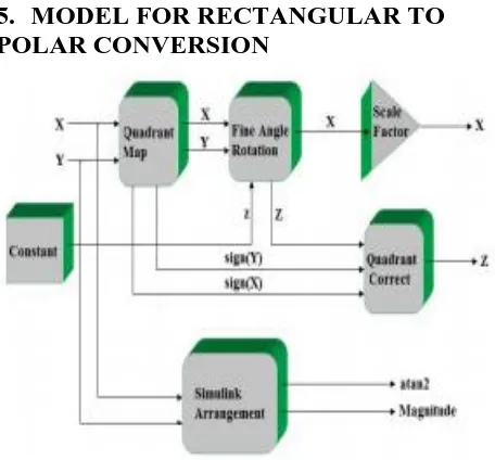
Figure 3 Rectangular to Polar Conversion Finite Precision Model
A finite precision model of the presented architecture has been performed using System Generator tool. The architecture contains the CORDIC processor and a separate rectangular-to-polar conversion implemented using Simulink blocks. The CORDIC algorithm converges for angles between -900 to +900. The Quadrant Map always maps the
absolute value for x-axis. This reflects the input vector from the second and third quadrant to the first and fourth quadrant respectively. This process is called Coarse Angle Rotation.
The Fine Angle Rotation operation is performed iteratively in in stages (0,1,2……,stages-1). The i-th Processing Element rotates its input vector by an angle +/- atan(1/2^i) driving its input Y-coordinate towards zero. The Quadrant Correct subsystem reflects the angle back to the second and third quadrant fromthe first and fourth quadrant if reflection was applied during the Quadrant Map stage. Reflection is applied by subtracting the output angle by 1800 if the originalvector was in the second quadrant and by (-1800) if was in the third quadrant.
6.
HARDWARE IMPLEMENTATION
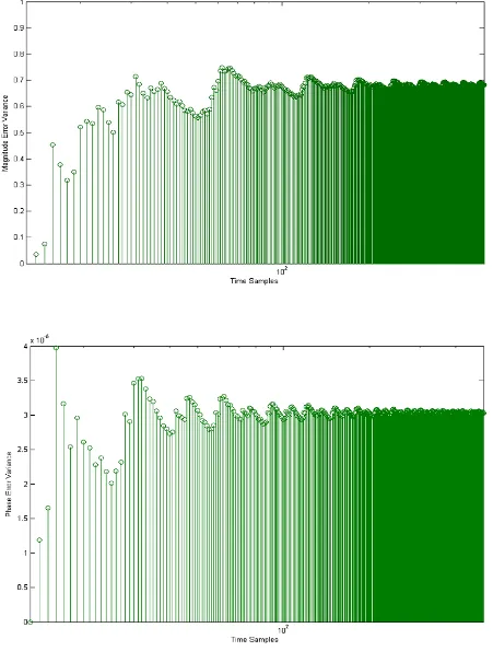
Fig. 4 shows the resulting magnitude and phase error variance when the precision model was excited with a finite pattern of input time. The magnitude error variance data statistics showed that the maximum error variance limits to 7.48e-006 and mean approximation error limits to 6.691e-006 with standard deviation equals to 6.329e-007, whereas for the phase error variance data
investigation, these were limited to 3.974e-005, 3.011e-005 and 2.132e-006 respectively.
The proposed architecture was implemented in an XC2V3000-4FG676 Xilinx FPGA device. Area and maximum working frequency were obtained with the 10.1 Xilinx ISE tool and no asynchronous control signals are used in the design.
The results of the implementation using fully CORDIC approach are given in Table I for different precision values. These results indicate that even the circuit with higher precision achieves a working frequency suitable for wireless communication applications.
6.1
Comparison with other implementation
strategies
In this section the proposed rectangular to polar conversion architecture is compared with other implementation [16] that uses LUT-based approach on FPGA that were optimized to minimize the hardware resources of the device. Table II shows the results of the implementation using uniform segmentation LUT-based method. The proposed RPC is compared with other implementations on the same target device and whereas [16] is providing only phase, ours is computing the phase as well as the magnitude.
TABLE I. PERFORMANCE OF THE PROPOSED ARCHITECTURE BASED ON FULLY PARALLEL CORDIC
Precision
12
14
16
18
20
22
#Mult 18x18
0
0
0
0
0
0
#Slices
217
253
295
330
367
402
#LUT4
326
381
451
507
563
619
#Flip-flops
370
432
507
571
635
699
#Block-RAM
0
0
0
0
0
0
F
max(MHz)
177.62 174.338 171.174 168.124 165.18 162.338
TABLE II. PERFORMANCE OF THE ARCHITECTURE BASED ON LUT-BASED APPROACH [16]
Precision
12
14
16
18
20
22
#Mult 18x18
2
2
2
2
6
6
#Slices
254
333
365
400
538
575
#LUT4
397
531
550
642
938
1010
#Flip-flops
135
145
130
138
135
140
#Block-RAM
1
1
2
2
5
5
F
max(MHz)
58.9
52.9
49.8
48.6
46.8
45.6
7.
CONCLUSION
This paper has presented an architecture for rectangular-to- polar conversion using an iterative linear convergence algorithm CORDIC. The architecture has been modelled using System Generator and implemented in a Virtex 2 Xilinx Device. The implementation has been compared with a multipartite LUT-based approach. The speed advantage of the proposed design is that it gives the output in just one clock cycle, whereas LUT-based approaches take comparatively long time to maintain tables. The hardware implementation of RPC using CORDIC on FPGA is done as the FPGAs can give enhanced speed at low cost with a lot of flexibility. The proposed design increases the maximum frequency, reduces the number of FPGA slices and is not utilizing multipliers and BRAMs with respect to LUT-based architecture. As a result, the proposed architecture is most suitable for high speed wireless communications and provides an alternative for
multimode and multiband operations that can support various modulation formats such as EDGE, GSM, CDMA, TDMA, and WCDMA.
8.
ACKNOWLEDGMENTS
[image:6.595.95.504.344.563.2]9.
REFERENCES
[1] G. Baudoin, M. Villegas, M. Suarez, A. Diet, F. Robert, “Performance analysis of multiradio transmitter with polar or cartesian architectures associated with high efficiency switched-mode power amplifiers,” RadioEngineering, vol. 19, no. 4, 2010, pp. 470-478. [2] Y. Huang, J. H. Mikkelsen, and T. Larsen, “
Investigation of polar transmitters for WCDMA handset applications,” Proc. 24th Norchip Conference, 2006, pp.
155-158.
[3] In-Seok Jung, Yong-Bin Kim, ”A CMOS low-power digital polar modulator system integration for WCDMA transmitter,” IEEE Transactions on Industrial Electronics, vol. 59, no. 2, 2012, pp. 1154-1160. [4] Sunho Kim, Jino Oh, Sungbin Im, “Performance
comparison of Taylor series approximation and CORDIC algorithm for open-loop polar transmitters,” IEEE International Conference on Consumer Electronics (ICCE), 2011, pp. 425-426.
[5] Parhami, Behrooz, “ Computer arithmetic – algorithms and hardware design,” New York : Oxford University Press, Second Edition, 2009.
[6] Volder, Jack, “The birth of CORDIC,” Journal of VLSI signal processing systems for signal, image and video technology, vol. 25, 2000, pp. 101-105.
[7] Brent, Richard P., “Fast multiple-precision evaluation of elementary functions,” Journal of the association for computing machinery, vol. 23, 1976, pp. 242-251. [8] R. Gutierrez, J. Valls, “Implementation of FPGA of a
LUT-based atan(y/x) operator suitable for synchronization algorithms,” IEEE, 2007, pp. 472-475.
[9] J. Volder, “The CORDIC trigonometric computer technique,” IRE Trans. Electron. Comput., vol. EC-8, 1959, pp. 330–334.
[10]R. Andraka, “A survey of CORDIC algorithms for FPGA based computers,” in Proc. ACM/SIGDA 6th Int. Symp. FPGAs, Monterey, CA, 1998, pp. 191-200.
[11]F. Angarita, A. Perez-Pascual, T. Sansaloni, J. Valls, “Efficient FPGA implementation of CORDIC algorithm for circular and linear coordinates,” IEEE, 2005, pp. 535-538.
[12]J. S. Walther, “The story of unified CORDIC,” Journal of VLSI Signal Processing, vol. 25, no. 2, 2000, pp. 107-112.
[13]Anurag Vijay Agrawal, Rajesh Mehra, “ Reconfigurable design of rectangular to polar converter using linear convergence,” International Journal of Computer Applications, vol. 50, no. 5, 2012, pp. 23-27.
[14]J. Sudha, M. C Hanumantharaju, V. Venkateswarula, Jayalaxmi H, “A novel method for computing exponential function using CORDIC algorithm”, Elsevier, SciVerse ScienceDirect, Procedia Engineering 30, 2012, pp. 519-528.
[15]H.Y. Ko, Y. C. Wang, A. Y. Wu, “Digital signal processing engine design for polar transmitter in wireless communication systems,” Proc. of IEEE ISCAS Conference, 2005, pp. 6026-6029.
![Figure 1 Rotation in Circular Coordinates [11]](https://thumb-us.123doks.com/thumbv2/123dok_us/8087801.784052/2.595.332.567.237.416/figure-rotation-in-circular-coordinates.webp)
![Figure 2 Fully Parallel CORDIC[13]](https://thumb-us.123doks.com/thumbv2/123dok_us/8087801.784052/3.595.322.539.70.395/figure-fully-parallel-cordic.webp)