OBSTACLE AVOIDANCE ROBOT APPLYING FUZZY CONTROL SYSTEM
LIEW CHIA WOON
A project report submitted in partial
fulfillment of the requirement for the award of the
Master of Electrical Engineering
Faculty of Electrical and Electronic Engineering
Universiti Tun Hussein Onn Malaysia
iv
ABSTRACT
v
ABSTRAK
vi
CONTENTS
TITLE i
DECLARATION ii
ACKNOWLEDGEMENT iii
ABSTRACT iv
CONTENTS vi
LIST OF TABLES ix
LIST OF FIGURES x
LIST OF SYMBOLS AND ABBREVIATIONS xiii
LIST OF APPENDICES xiv
CHAPTER 1 INTRODUCTION 1
1.1 Project Background 1
1.2 Problems Statement 2
1.3 Project Objectives 3
1.4 Project Scopes 3
1.5 Thesis Outline 3
CHAPTER 2 LITERATURE REVIEW 5
2.1 Introduction 5
2.2 Description of Previous Methods 5
vii
2.4 Kinematics Model 11
2.5 Typical Mobility Configurations 14
2.5.1 Differential Drive 14
CHAPTER 3 METHODOLOGY 16
3.1 Project Methodology 16
3.2 Fuzzy Controller Design and Modeling 16
3.2.1 Obstacle Avoidance 17
3.2.2 Robot Behavior 19
3.3 Operation of the Robot 24
3.4 Hardware Components 26
3.4.1 Ultrasonic Sensor 26
3.4.2 dsPIC30F4011 Microcontroller 30
3.4.3 Motor Driver MC33886 31
3.4.4 DC Motor 32
3.4.5 Quadrature Encoder 33
3.5 Software Development 35
CHAPTER 4 DATA ANALYSIS AND RESULTS 37
4.1 Simulink Model of the Robot 37
4.2 FIS Editor 38
4.3 Matlab Simulink Result 43
4.4 Robot System 50
viii
4.4.2 Behavior of the Robot during Avoiding
the Obstacles 53
4.5 Limitations 58
CHAPTER 5 DISCUSSION AND CONCLUSIONS 59
5.1 Conclusion 59
5.2 Recommendation for Future Work 60
REFERENCES 61
APPENDIX 64
ix
LIST OF TABLES
3.1 Fuzzy rule for velocity of the left motor 18 3.2 Fuzzy rule for velocity of the right motor 19 3.3 List of rules for the obstacle avoidance 19
3.4 Parameters for object distance 20
3.5 Parameters for object difference 21
3.6 Parameters for left motor 21
3.7 Parameters for right motor 21
x
LIST OF FIGURES
2.1 Fuzzy Logic Controller 8
2.2 Sugeno rule operator 9
2.3 The example of fuzzy tipping model developed
by using Sugeno system. 10
2.4 Kinematics model of the robot 11
2.5 A typical differential-drive mobile robot (robot
view) 14
3.1 Block diagram of fuzzy behaviour robot control
architecture 17
3.2 Block diagram of fuzzy based obstacle avoidance
robot control behaviour architecture 18 3.3 Rules viewer for the membership functions 22
3.4 Flow chart of robot operation 25
3.5 Design concept 26
3.6 Sensors location 27
3.7 Ultrasonic sensor HC-SR04 27
3.8 General diagram of ultrasonic sensor 28
3.9 Timing diagram of HC-SR04 28
3.10 Ultrasonic working principle 29
3.11 dsPIC30F4011 package layout and pin
configuration 30
3.12 dsPIC30F4011 pin assignment 30
3.13 33886 simplified application diagram 31
3.14 Truth table of MC33886 32
3.15 DC Motor 32
3.16 Quadrature encoder output 34
3.17 MPLAB X IDE layout 35
xi
4.1 Simulink model of the robot 37
4.2 FIS Editor 38
4.3 Membership function for object distance 39 4.4 Membership function for object different 39 4.5 Membership function of Sugeno type for left
motor output 40
4.6 Membership function of Sugeno type for right
motor output 40
4.7 Rule editor 41
4.8 FIS surface view 41
4.9 Resultant left motor and right motor velocities in
RuleView of Sugeno FIS 42
4.10 The sensors inputs of case 1 44
4.11 Simulation result when obstacle detected at 100 cm from left sensor, 100 cm from right
sensor, and 50 cm from right sensor (case 1) 44
4.12 The sensors inputs of case 2 45
4.13 Simulation result when obstacle detected at 50 cm from left sensor, 100 cm from right sensor, and
100 cm from right sensor (case 2) 46
4.14 The sensors inputs of case 3 46
4.15 Simulation result when obstacle detected at 100 cm from left sensor, 100 cm from right
sensor, and 100 cm from right sensor (case 3) 47
4.16 The sensors inputs of case 4 47
4.17 Simulation result when obstacle detected at 100 cm from left sensor, 100 cm from right
sensor, and 30 cm from right sensor (case 4) 48
4.18 The sensors inputs of case 5 48
4.19 Simulation result when obstacle detected at 30 cm from left sensor, 100 cm from right sensor, and
100 cm from right sensor 49
4.20 Main components of the robot 50
xii
4.22 Two wheels robot with ultrasonic sensors 51 4.23 Experiment environment of obstacle avoidance
robot 52
4.24 Robot moving forward when the front direction is
clear 53
4.25 Robot turning right when left and front obstacle
detected 53
4.26 Robot moving forward when front sensor is clear 54 4.27 Robot turns right when obstacle detected at left
and right of the sensor 54
4.28 Robot moving forward with medium velocity when left, right obstacles in medium distance and
front obstacle is fat away from the front sensor 55 4.29 Robot move forward and turning left when detect
obstacle in front and right of the sensor 55 4.30 Robot navigation in a complicated situation
without suffering from the dead cycle problem 56 4.31 Robot turns left and move out from the L-shape
corner 56
4.32 The robot turn left when the right obstacle detected is near, where front and left obstacle is
far 57
xiii
LIST OF SYMBOLS AND ABBREVIATIONS
cm - Centimetre DC - Direct Current
FIS - Fuzzy Inference System FLC - Fuzzy Logic Controller
ICC - Instantaneous Center of Curvature KHz - Kilohertz
- distance between the two wheels PIC - Peripheral Interface Controller PID - Proportional-Integral-Derivative PWM - Pulse Width Modulation - nominal radius of each wheel
R - instantaneous curvature radius of the robot trajectory, relative to the mid-point of the wheel axis.
- Linear velocity of left wheel(cm/s) - Linear velocity of right wheel(cm/s) - angular velocity of left wheel
xiv
LIST OF APPENDICES
APPENDIX TITLE PAGE
CHAPTER 1
INTRODUCTION
1.1 Project Background
In recent years, research and application employing non-analytical methods of
computing such as fuzzy logic, evolutionary computation, and neural networks have demonstrated the utility and potential of these paradigms for intelligent control of complex system. In particular, fuzzy logic has proven to be a convenient tool for handling real world uncertainty and knowledge representation [1, 2-4].
Fuzzy logic based approach has been successfully to control nonlinearity, uncertainty and complexity system recently. Fuzzy control system is suited to apply for autonomous mobile robots which have complex control architectures. The design of the autonomous robots is complex because of the uncertain input signal from the unknown environments and sensor inputs. The autonomous robot cannot be developed by using only the microcontroller and input signals from the ultrasonic sensors. Thus, the behaviour-based control architecture such as obstacle avoidance behaviour and wall following behaviour will be used to control the robot.
2
1.2 Problems Statement
There are many approaches have been proposed to solve the problem, such as PID controller, behaviour-based methods, neural network methods, and some others methods [5,6]. Problem with the differential term in PID controller is that small amounts of noise can cause large amounts change in the output. In the previous research, performance analysis of the conventional PID controller and fuzzy logic controller has been done by the use of Matlab and Simulink and in the end comparison of various time domain parameters is done to prove that the fuzzy logic controller has better stability, small overshoot and fast response as compared to PID controller. Another problem faced with PID controllers is that they are linear. The performance of PID controllers in non-linear systems is variable. Often PID
controllers are enhanced through methods such as scheduling or fuzzy logic.
Behaviour-based methods have been widely used for navigation of mobile robot such as line navigation and wall navigation method. Using wall navigation, not all the paths for robot movement is along the walls. Robot will detect far distance or false reading of wall if the robot crossing the space located at walls. By using line navigation, not all surface of the floor suitable can be planted a line as guidance.
Furthermore, in the sensors part, most sensors will occasionally generate noise in their output. For example, an infrared sensor might indicate the infrared light is present when actually no light is present. Or, a proximity sensor might give a questionable reading. If the noise is predictable enough, it can be filtered out in software. The noisy IR sensor might not be trusted until it gives some number of consecutive readings in agreement with one another. Affiliated with the problem of noisy data is missed data, where for either electrical or software reasons, a sensor reading is not detected or a touch sensor jams and fails to trigger. Besides, sensor data can also be adversely affected by ambient environmental conditions or battery strength.
3
1.3 Project Objectives
The objectives for this project are:
a) To develop a two wheels obstacle avoidance robot that can avoid unknown or unexpected obstacles in an unknown environment.
b) To design Sugeno fuzzy logic controller for the obstacle avoidance robot. c) To embedded the Sugeno fuzzy control into the robot.
d) To test the robot performance at real time.
1.4 Project Scopes
In order to achieve the objectives of the project, there are several scopes had been outlined. The scopes of the project are:
a) Develop the hardware for the system.
b) Ultrasonic sensors are applied as an obstacle detection of the robot. The detection range is within 3 cm until 300 cm.
c) Robot develop consists of two wheels and each of them are drive using DC motor.
d) Fuzzy logic inference method used in this project is Sugeno Fuzzy Logic. e) The robot able to avoid the obstacles on the flat surface, from any starting point.
1.5 Thesis Outline
The thesis is divided into five chapters. Chapter 1 the introduction, Chapter 2 is
4
CHAPTER 2
LITERATURE REVIEW
2.1 Introduction
In order to design and develop an obstacles avoidance robot by using fuzzy logic
controller, extensive research on the fuzzy controller need to be fulfilled. This
section will discuss previous studies that have been accomplished by other
researchers in the same area.
2.2 Description of Previous Methods
Some previous methods that have been developed by other researchers are reviewed.
Qing-yonget all. [7] have developed a bahavior-based mobile robot navigation in unknown environment by using fuzzy logic. There are four basic
behaviors used in their mobile bot navigation which is goal behaviour, obstacle
avoidance behaviour, tracking behaviour, and deadlock disarming behaviour. These
basic behaviors were implemented by using fuzzy logic controller. A behaviour
controller is designed to determine the control action of the mobile robot. The
simulation experimental results showed that the proposed architecture enables the
mobile robot to safely achieve the goal without colliding.
Limen, et all. [8] developed a new fuzzy intelligent obstacle avoidance control strategy for wheeled mobile robot, which is composed of two fuzzy logic
controllers and an intelligent coordinator. Fuzzy obstacle controller will generate
obstacle avoidance commands according to the target orientation information and
6
Intelligent coordinator is designed to coordinate run-to-goal fuzzy controller and
fuzzy obstacle and generate ultimate robot control commands.
Mobile robot control using type-2 fuzzy logic system was developed by Pisit
and Supachai [9]. Type-2 fuzzy sets are described by membership functions that are
themselves fuzzy and output processor of a type-2 fuzzy contains two components:
type-reduction and defuzzification. The type-2 fuzzy logic controller will process
data output to control the direction of the mobile robot movement. The
behaviour-based control was obstacle avoidance and corridor following. The results obtained
demonstrate the efficiency of type-2 fuzzy logic control system and the ability to
solve the problems.
Ability of a robot to avoid collision with unforeseen or dynamic obstacles
while it is moving towards a target or tracking a path is a vital task in autonomous
navigation. Navigation strategies can be classified to global path planning and local
path planning.
In global path planning, information about the obstacles and a global model
of environment is available which mostly Configuration space, Road map, Voronoi
diagram and Potential field techniques are used to plan obstacle-free path towards a
target. However, in real world a reliable map of obstacle, accurate model of
environment and precise sensory data is unavailable due to uncertainties of the
environment. While the computed path may remain valid but to response the
unforeseen or dynamic obstacles, it is necessary for the robot to alter its path online.
In such situations, Fuzzy logic can provide robust and reliable methodologies dealing
with the imprecise input with low computational complexity [10]. Different obstacle
avoidance approaches were developed during past decades which proposed effective
solution to the navigation problems in unknown and dynamic environments.
Zavlangaset all. [11] developed a reactive navigation method for omnidirectional mobile robots using fuzzy logic. The fuzzy rule-base generates
actuating command to get collision free motions in dynamic environment. The fuzzy
logic also provides an adjustable transparent system by a set of learning rules or
manually. Seraji and Howard developed a behavior-based navigation method on
challenging terrain using fuzzy logic. The navigation strategy is comprised of three
behaviors. Local obstacle avoidance behaviour is consists of a set of fuzzy logic rule
7
Chee et all. [13] presented a two-layer fuzzy inference system in which the first layer fuses the sensor readings. The left and right clearances of the robot were
found as outputs of the first-layered fuzzy system. The outputs of the first layer
together with the goal direction are used as the inputs of the second-layer.
Eventually, the final outputsof the controller are the linear velocity and the turning
rate of the robot. The second-stage fuzzy inference system employs the collision
avoiding, obstacle following and goal tracking behaviours to achieve robust
navigation in unknown environments. Dadios and Maravillas proposed and
implemented a fuzzy control approach for cooperative soccer micro robots. A
planner generates a path to the destination and fuzzy logic control the robot’s
heading direction to avoid obstacles and other robots while the dynamic position of
obstacles, ball and robots are considered [14].
Parhi described a control system comprises a fuzzy logic controller and a
Petri Net for multi robot navigation. The Fuzzy rules steer the robot accordingto
obstacles distribution or targets position. Since the obstacle’s position is not known
precisely, to avoid obstacles in a cluttered environment fuzzy logic is a proper
technique for this task. Combination of the fuzzy logic controller and a set of
collision prevention rules implemented as a Petri Net model embedded in the
controller of a mobile robot enable it to avoid obstacles that include other mobile
robots [15].
A fuzzy controller designed by Lilly for obstacle avoidance of an autonomous
vehicle using negative fuzzy rules. The negative fuzzy rules define a set of actions to
8
2.3 Fuzzy Control System
The present project uses a Fuzzy Decision Making Controller which is a type of
fuzzy logic controller (FLC). This type of Fuzzy Logic can be used for controlling a
process i.e., a plant in control engineering terminology which is non-linear. The
advantage of FLC is that it enables control engineers to easily implement control
strategies which can be used by a human operator.
The components of FLC are an inference engine and a set of linguistic
IF-THEN rules that encode the behaviour of the mobile robot. However, the main
difficulty in designing a fuzzy logic controller is the efficient formulation of the
fuzzy IF-Then rules. If it is easy to produce the antecedent parts of a fuzzy rule base,
it is however very difficult to produce the consequent parts without expert
knowledge [17]. Figure 2.1 shows the Fuzzy Decision Making controller is made up
of three steps:
1) Fuzzification: Converts controller inputs into information that the
inference mechanism can be easily use to activate and apply rules.
2) Rule base: A set of IF-Then rules which contains a fuzzy logic
quantification of the expert’s linguistic description of how to achieve
good control.
3) Defuzzification: This converts the conclusions of the interface mechanism
[image:20.595.121.524.523.669.2]into actual inputs for the process.
9
There are three main fuzzy inference systems (fuzzy logic approximators)
which is Mamdani, Sugeno, and Tsukamoto type. In this project, Sugeno system is
used.
Sugeno, or Takagi-Sugeno-Kang, method of fuzzy inference. Introduced in
1985,it is similar to the Mamdani method in many respects. The first two parts of the
fuzzy inference process, fuzzifying the inputs and applying the fuzzy operator, are
exactly the same. The main difference between Mamdani and Sugeno output
membership functions are either linear or constant.
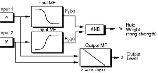
A typical rule in a Sugeno fuzzy model has the form
If input 1 = x and input 2 = y, then output is z = ax + bx + c
For a zero-order Sugeno model, the output level z is a constant (a=b=0).
The ouput level of each rule is weighted by the firing strength of the rule.
For example, for an AND rule with input 1 = x and input 2 = y, the firing
strength is
= ℎ (,)
Where ,(. ) are the membership functions for input 1 and 2. The final output of
the system is the weighted average of all rule outputs, computed as
Final Output= ∑ wiZi N i=1
∑ wi
N i=1
(2.1)
[image:21.595.175.478.488.628.2]A Sugeno rule operators as shown in the following diagram.
10
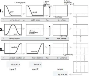
Figure 2.3: The example of fuzzy tipping model developed by using Sugeno system.
Fuzzy based systems are constructed so that generated outputs change in a
smooth and continuous manner, regardless of inputs crossing set boundaries. System
inputs undergo three transformations to become system outputs. First a fuzzification
process uses predefined membership functions to map each system input into one or
more degrees of membership. Then the rules in the rule base are evaluated by
combining degrees of membership to form output strengths. Lastly the
defuzzification process computes system outputs based on these output strengths and
11
2.4 Kinematics Model
The robot has two identical parallel, wheels attached to both sides of the vehicle
which are controlled by two independent DC motors. The velocity of the center of
mass of the robot is orthogonal to the wheels’ axis, L. The center of mass of the robot
is located in the middle of the axis connecting the wheels (L). The Figure of
[image:23.595.221.423.235.383.2]kinematics model is shown in Figure 2.2.
Figure 2.4: Kinematics model of the robot.
The angular velocities (and ) of the two wheels are independently
controlled [20]. The equations that are used to build a Matlab Simulink model of the
are given by relation [21]:
= linear velocity of right wheel
= linear velocity of left wheel
ωrt=angular velocity of right wheel
(t) = angular velocity of left wheel
= nominal radius of each wheel
= distance between the two wheels
R= instantaneous curvature radius of the robot trajectory, relative to the
mid-point of the wheel axis.
12
−
2= Curvature radius of trajectory decribed by left wheel
+
2= Curvature radius of trajectory decribed by right wheel
With respect to ICC the angular velocity of the robot is given as follows:
ωt= Vr(t) R+(L 2)
(2.2)
ωt= Vl(t) R-(L
2)
(2.3)
ωt= Vrt- Vlt
L 2.4
The instantaneous curvature radius of the robot trajectory relative to the mid-point
axis is given as
R= L (Vlt+ Vrt) 2(Vlt- Vrt)
(2.5)
Therefore, the linear velocity of the robot is given as
Vt= ωtR= Vrt+ Vlt
2 (2.6)
The kinematics equations in the world frame can be represented as follows.
= (2.7)
= (2.8)
=() (2.9)
This implies
= cos ! (2.10)
13
= (2.12)
The above equation can also be represented in the following form
"
()
()
()
#= $
% 0
0
0 1
& '(())(
= "
%
sin
()
#
= "
(+% )/2
(+)/2
(−)/2
# (2.13)
These are the equations that are used to build a model of the robot. These
equations were used to simulate the robot in MATLAB Simulink. The fuzzy logic
14
2.5 Typical Mobility Configurations
The accuracy of odometry measurements for dead reckoning is to a great extent a
direct function of the kinematic design of a vehicle. Because of this close relation
between kinematic design and positioning accuracy, one must consider the kinematic
design closely before attempting to improve dead reckoning accuracy.
2.5.1 Differential Drive
Figure 2.5 shows a typical differential drive mobile robot. In this design incremental
encoders are mounted onto the two drive motors to count the wheel revolutions. The
robot can perform dead reckoning by using simple geometric equations to compute
[image:26.595.194.446.397.565.2]the momentary position of the vehicle relative to a known starting position.
Figure 2.5: A typical differential-drive mobile robot (robot view) [22].
For completeness, rewrite the well-known equations for odometry below (also,
see [Klarer, 1988; Crowley and Reignier, 1992]). Suppose that at sampling interval I
15
Suppose further that
% */ (2.14)
Where
= conversion factor that translates encoder pulses into linearwheel
displacement
* = nominal wheel diameter (in mm)
% = encoder resolution (in pulse per revolution)
= gear ratio of the reduction gear between the motor (where the encoder
is attached) and the drive wheel.
The incremental travel distance for the left and right wheel, ∆+, and ∆+, according
to
∆+/, = %)/, (2.15)
and the incremental linear displacement of the robot’s center point , denoted ∆+,
according to
∆+= (∆++ ∆+)/2 (2.16)
Next, the robot’s incremental change of orientation
∆ = (∆+− ∆+)/ (2.17)
where is the wheelbase of the vehicle, ideally measured as the distance between the
two contact points between the wheels and the floor.
The robot’s new relative orientation can be computed from
= + ∆ (2.18)
and relative position of the center point is
= + ∆+cos (2.19a)
= + ∆+ (2.19b)
Where
CHAPTER 3
METHODOLOGY
3.1 Project Methodology
This chapter deals specifically with the implementation of the fuzzy logic controller in the microcontroller as well as in Matlab. Simulink was used to simulate the mobile robot for testing as well as tuning the fuzzy logic controller. Firstly, the fuzzy logic toolbox that was available was used. The fuzzy logic controller was built using the fuzzy logic toolbox, which contains graphical interface.
Sugeno method inference is used because Sugeno method is computationally efficient which suitable for microcontroller application. There was different types of membership functions were tested and also the ranges of the membership functions can be tweaked to search for an optimum result. The rules developed also can be changed and the effect observed and defuzzification was tested.
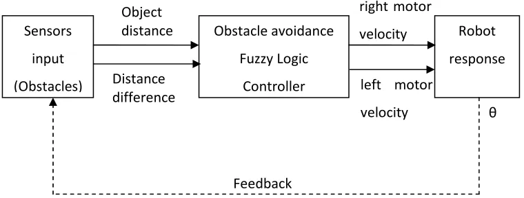
3.2 Fuzzy Controller Design and Modeling
In this project, the Fuzzy Logic Controller (FLC) designed to control the motion of the robot. There have two inputs which is distance sensor and distance difference of the robot. The two outputs are left motor velocity (left motor-v) and right motor velocity (right motor-v). Thus, the FLC is a two inputs and two outputs system.
In this project, Matlab’s Fuzzy Logic Toolbox was used to design the FLC. The Matlab’s Fussy Logic Toolbox contains functions, graphical user interfaces
17
Figure 3.1: Block diagram of fuzzy behavior robot control architecture
3.2.1 Obstacle Avoidance
Distance crisp value between robot and surrounding objects measure by ultrasonic sensor circuit for distance measurement which used to build the fuzzy membership
function. The acquired information from the sensors shows that there exist obstacles nearby robot. When a robot is close to an obstacle, it must change its velocity and steering angle to avoid the obstacle.
Feedback
θ Distance
difference left motor
velocity right motor
velocity Object
distance Obstacle avoidance
Fuzzy Logic
Controller
Robot
response Sensors
input
18
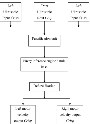
Figure 3.2: Block diagram of fuzzy based obstacle avoidance robot control behavior architecture.
The fuzzy rules used for obstacle avoidance by the robots are listed in Table
3.3 as rules 1 to 9. All the rules in the table are obtained heuristically.
Table 3.1: Fuzzy rule for velocity of the left motor.
Left motor velocity, (cm/s) Object distance, (cm)
Near Medium Far
Object
difference,
(cm)
Negative Fast Medium Medium
Zero Slow Medium Fast
Positive Fast Slow Slow
Left Ultrasonic Input Crisp
Front Ultrasonic
Input Crisp
Left Ultrasonic Input Crisp
Fuzzification unit
[image:30.595.108.521.643.749.2]19
Table 3.2: Fuzzy rule for velocity of the right motor.
Right motor velocity, (cm/s) Object distance, (cm)
Near Medium Far
Object
difference,
(cm)
Negative Slow Slow Slow
Zero Slow Medium Fast
Positive Slow Medium Medium
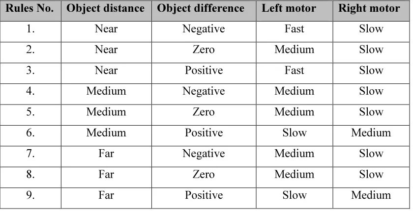
Table 3.3: List of rules for obstacle avoidance.
Rules No. Object distance Object difference Left motor Right motor
1. Near Negative Fast Slow
2. Near Zero Medium Slow
3. Near Positive Fast Slow
4. Medium Negative Medium Slow
5. Medium Zero Medium Slow
6. Medium Positive Slow Medium
7. Far Negative Medium Slow
8. Far Zero Medium Slow
9. Far Positive Slow Medium
3.2.2 Robot Behavior
The robot has two wheels powered by separate DC motors and two castors are provided for stability of the robot. The sensors for measuring the distances around it from front obstacle distance, left obstacle distance, and right obstacle distance. The distance between the robots and obstacles act as repulsive forces for avoiding the
obstacles.
According to the information acquired by the robot using their sensors, some
[image:31.595.108.528.253.468.2]20
In this project, three types of membership functions are considered. First one is the three-membership function having two trapezoidal members and one triangular member. Linguistic variables such as “Near”, “Medium” and “Far” are taken for three-membership function.
Some of the fuzzy control rules are activated according to the information acquired by the robot using sensors. The outputs of the activated rules are weighted by fuzzy reasoning and the velocities of the driving wheels of the robot are calculated. Left wheel velocity and right wheel velocity are denoted as left motor and
right motor respectively as shown in Table 3.3.
Linguistic variables “Slow”; “Medium” and “Fast” are defined for left motor velocity and right motor velocity for three membership functions. Terms like “Slow”, “Medium”, and “Fast” are considered for left wheel velocity and right wheel velocity for three membership functions.
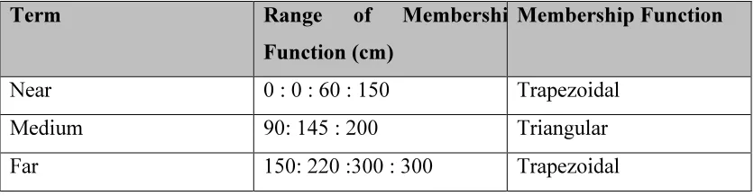
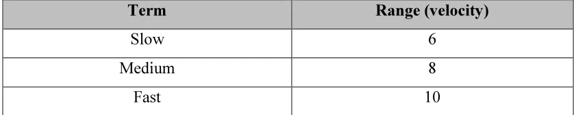
[image:32.595.108.526.512.621.2]The parameter input and output membership functions were defined as Table 3.4 until Table3.7 respectively. Values in the tables present values of x-axis in a kind of singular points. That is, “ 0 : 0 : 60 : 150” is values of x-axis in singular points for a fuzzy membership function “Near” of input fuzzy variables and “6” is value of x-axis in singular points for a fuzzy membership function “Slow” of output fuzzy variables.
Table 3.4:Parameters for object distance
Term Range of Membership
Function (cm)
Membership Function
Near 0 : 0 : 60 : 150 Trapezoidal
Medium 90: 145 : 200 Triangular
21
Table 3.5: Parameters for object difference
Term Range of Membership
Function (meter)
Membership Function
Negative -126 .-70 . -14 Trapezoidal
Zero -56 .0 .56 Triangular
[image:33.595.106.525.260.344.2]Positive 14 .70 .126 Trapezoidal
Table 3.6: Parameters for left motor
Term Range (velocity)
Slow 6
Medium 8
Fast 10
Table 3.7: Parameters for right motor
Term Range (velocity)
Slow 6
Medium 8
[image:33.595.105.526.400.487.2]22
Figure 3.3: Rules viewer for the membership functions.
These parameters used to generate different fuzzy rules:
If (object distance is near and object difference is negative Then (left motor is fast
and right motor is slow).
If (object distance is near and object difference is zero Then (left motor is slow and
right motor is slow).
If (object distance is near and object difference is positive Then (left motor is fast
and right motor is slow).
If (object distance is medium and object difference is negative Then (left motor is
medium and right motor is slow).
If (object distance is medium and object difference is zero Then (left motor is
medium and right motor is medium).
If (object distance is medium and object difference is positive Then (left motor is
slow and right motor is medium).
23
If (object distance is far and object difference is zero Then(left motor is fast and
right motor is fast).
If (object distance is far and object difference is positive Then(left motor is slow and right motor is medium).
24
3.3 Operation of the Robot
General program for the robot operation is created for robot rules. Figure3.4 shows the flow chart of the general robot operation. At first step the program read all sensors value that attached to the robot. Then the distance value of obstacle sensor is calculated. The program receives ranging data from the sensors then uses this to conduct the fuzzy logic operations. Robot then will make the turning to avoid the obstacle depend on the output of the fuzzy logic program. When the turning process is complete, the sensor detects or read again for the next input. If there is obstacle again, the avoiding process still running until there is no obstacle.
61
REFERENCES
1. R. Malhotra and A. Sarkar. Development of a Fuzzy Logic Based Mobile
Robot for Dynamic Obstacle Avoidance and Goal Acquisition in an
Unstructured Environment., IEEE/ASME Proceeding of International Con-
ference on Advanced Intelligent Mechatronics. 20- 24 July 2003. Kobe. pp.
235-247.
2. D. Ratner and P. McKerrow (2003). Navigation an Outdoor Robot along
Continuous Landmarks with Ultrasonic Sensing. Robotics and Autonomous
Systems, 45(1). Retrieved November 23, 2013, from doi:
10.1016/S0921-8890(03)00096-4
3. R. Carelli and E. O. Freire (2003). Navigation Outdoor and Wall-Following
Stable Control for Sonar-Based Mobile Robots. Robotics and Autonomous
Systems, 45(3). Retrieved November 24, 2013, from doi:
10.1016/j.robot.2003.09.005
4. R. Benporad, M. Di Marco and A. Tesi. Wall-Following Controller for
Sonar-Based Mobile Robots. Proceeding of IEEE Conference on Decision
and Control, San Diego. 10-12 December 1997. San Diego. pp. 3063-3068.
5. W. L. Xu and S. K. Tso. Real-time Self-reaction of a Mobile Robot in
Unstructured Enviroments using Fuzzy Reasoning. Engng Applic Aritif.
Intell. 1996. pp. 475-485.
6. Anmin Zhu and Simon X.Yang. A Fuzzy-logic Approach to Reactive
Navigation of Behavior-based Mobile Robots. IEEE International
Conference on Robotics & Automation. April, 2004, pp. 5054-5050.
7. BAO Qing-yong, LI Shun-ming, SHANG Wei-yan, & AN Mu-jin (2009). A
Fuzzy Behavior-Based Architecture for Mobile Robot Navigation in
Unknown Enviroments. IEEE. pp. 257-261.
8. Limin Ren, Weidong Wang & Zhijiang Du (2012). New Fuzzy Intelligent
Obstacle Avoidance Control Strategy for Wheeled Mobile Robot. IEEE.
62
9. PisitPhokharatkul & SupachaiPhaiboon. Mobile Robot Control Using Type-2
Fuzzy Logic System. IEEE. 2004.296-299.
10. Yanik, P., Ford, G., & Howell, B. An introduction and literature review of
fuzzy logic applications for robot motion planning. Proceedings of ASEE
Southeast Section Conference. Western Carolina University. 2010. 1-10.
11. Zavlangas, P.G., Tzafestas, S.G., & Althoefer, K. Fuzzy Obstacle Avoidance
and Navigation for Omnidirectional Mobile Robots. ESIT. 2000. 375-382.
12. Seraji, H. & Howard, A. Behavior-based robot navigation on challenging
terrain: A fuzzy logic approach. IEEE Trans. Robotics and Automation.
2002. (18): 308-321.
13. Chee, B. Y., Lang, S.Y.T., & Tse, P.W.T. Fuzzy mobile robot navigation and
sensor integration. IEEE International Conference on Fuzzy Systems. New
Orleans, LA. 1996. 1: 7-12.
14. Dadios, E. & Maravillas, O. Cooperative Mobile Robots with Obstacle and
Collision Avoidance Using FuzzyLogic. Proceedings of IEEE International
Symposium on Intelligent Control. October 27-30, 2002. Vancouver, Canada:
IEEE, 2002. 75-80.
15. Parhi, D.R. Navigation of mobile robots using a fuzzy logic controller.
Journal of intelligent and robotic systems. 2005. 42(3): 253–273.
16. Lilly, J.H. Evolution of a negative-rule fuzzy obstacle avoidance controller
for an autonomous vehicle. IEEE Trans. Fuzzy System. 2007. 15: 718-728.
17. J. M. Lucas, H. Martinez-Barbera, & F. Jimenez. Multi-objective
Evolutionary Fuzzy Modeling for the Docking Maneuver of an Automated
Guided Vehicle. IEEE International Conference on System, Man and
Cybernetic. 2005. 4: pp. 2999-3004.
18. Rerngwut Choomuang and Nitin Afzulpurkar. Hybrid Kalman Filter/Fuzzy
Logic based Pasition Control of Autonomous Mobile Robot. International
Journal of Advanced Robotic Systems. 2005.2: pp. 197-208.
19. The MathWorks, Inc (2009), MATLAB Fuzzy Logic Toolbox.
20. Vamsi Mohan Peri. Fuzzy Logic Controller for an autonomous Mobile Robot.
Master’s Thesis. University of Jawaharlal Nehru Technological India; 2002.
21. Razif Rashid, I. Elamvazuthi, MumtajBegam, & M. Arrofiq. Fuzzy-based
Navigation and Contol of Non-Holonomic Mobile Robot. Journal of
63
22. J. Borenstein, H. R. Everett, & L. Feng. Where am I? Sensors and Methods
for Mobile Robot Positioning. United States: University of Michigan. pp.
19-20; 1996.
23. Ibrahim, M. T., Dirman Hanafi & Ruzlaini Ghoni. Autonomous Navigation
for a Dynamical Hexapod Robot using Fuzzy Logic Controller. International
Conference on Modeling Optimisation and Computing, Procedia Engineering
38. Elsevier Ltd. 2012. pp. 330-341.
![Figure 2.1: Fuzzy Logic Controller [18].](https://thumb-us.123doks.com/thumbv2/123dok_us/8767376.897150/20.595.121.524.523.669/figure-fuzzy-logic-controller.webp)

![Figure 2.5: A typical differential-drive mobile robot (robot view) [22].](https://thumb-us.123doks.com/thumbv2/123dok_us/8767376.897150/26.595.194.446.397.565/figure-typical-differential-drive-mobile-robot-robot-view.webp)