International Journal of Emerging Technology and Advanced Engineering
Website: www.ijetae.com (ISSN 2250-2459,ISO 9001:2008 Certified Journal, Volume 5, Issue 7, July 2015)
296
Application of STATCOM and SVC for Stability
Enhancement of FSIG based Grid Connected Wind Farm
Milap Shah
1, Prabodh Khampariya
2, Bhavik Shah
31,2Sri Satya Sai University of Technology and Medical Science, Sehore (M.P.), India, Pin: 466001 3Shree N.M. Gopani Polytechnic Institute, Ranpur (Botad), Gujarat, India, Pin: 382245
Abstract— Contribution of wind power is increasing
rapidly now-a-days. Induction generator based wind power plants exhibit a different behavior than synchronous generator based conventional power plants. In this paper, a model of wind farm based on FSIG, equipped with SVC and STATCOM is developed in MATLAB/SIMULINK. The Aim of this paper is to analyze transient stability of a wind farm based on fixed speed induction generators when it has been integrated with a weak grid. A Comparative analysis of the transient stability improvement of a FSIG based wind farm illustrates that, these devices considerably improve wind farm stability. In comparison with SVC, STATCOM is best choice for increasing stability of grid connected wind farms.
Keywords— Fixed Speed Induction Generator (FSIG), Power System Stability, SVC, STATCOM, Matlab/Simulink, Wind Farm, Wind Power Plant
I. INTRODUCTION
The expansion of power generation & transmission has been severely limited due to limited resources and environmental restrictions as the power demand has increased substainlly. Nowadays wind energy is widely used as non-pollutant energy and promising renewable energy resources in the world for electrical power generation. Adequate reactive power is not fed in a large wind farm due to which it is far away form its connection to power system. One of prime cause of voltage instability in the system is system voltage collapse. Partial or full power interruption in the system is due to the consequences of voltage collapse. The occurrence of Reactive power imbalance in the system is main cause of voltage instability in system. The occurrence of voltage collapse is prevented by reducing the reactive power load or to provide the system with additional supply of reactive power before the system reaches at the point of voltage collapse.
Wind power is abundant, renewable, widely spread, clean, an alternative to fossil fuels, rapidly growing source of energy and produces no greenhouse gas emissions during operation. Advantages of wind power can make it as s lucrative source of power for both utility-scale and small, distributed power generation applications.
At a location of wind farm, favorable wind speed range lies between 6m/s to 30m/s, in a small or medium size wind farm, there are 5 to 50 wind turbine generator units. In a large wind farm, there is a single unit of large wind turbine generator unit. Wind electrical energy conversion plants are available with battery storage support system and without battery storage system.
During 21st century, India has become 2nd leading wind
power market in India. Currently, Installed capacity of wind power market in India is close to 13 GW, with market growing at average rate of 20% over the past three years. In energy displacement plants, wind energy conversion plants are connected in parallel with electrical grid. When wind farm is installing in distribution system, the power quality of the distribution network has to be ensured. The power quality of generation must be ensured by maintain the electrical parameters of the distribution network. So, new problems are arises in the management and operation of energy transfer and distribution of renewable energy in the grids. So, the control of electric variables and reactive power control are required in wind farms.
Figure: Wind Turbine and Induction generator
International Journal of Emerging Technology and Advanced Engineering
Website: www.ijetae.com (ISSN 2250-2459,ISO 9001:2008 Certified Journal, Volume 5, Issue 7, July 2015)
297 Utilizing IG reactive power control capabilities, wind farm can reduce power losses and improve the voltage profiles in the distribution system. FSIG based wind farm equipped with SVC and STATCOM, connected to power system is simulated in MATLAB/SIMULINK. Impacts of SVC and STATCOM on power system are investigated during fault through and grid disturbance. Finally Comparison of SVC and STATCOM are carried out during disturbances.
Figure: Modular model of a grid-connected wind turbine Equipped with an induction generator
The electricity-producing wind turbine is treated as a complex electromechanical system consisting of the induction generator, the drive train system and the rotating wind turbine.
II. INTRODUCTION OF STATCOMAND SVC
Static Var Compensator (SVC):
SVC is reactive power generator or a kind of var static absorber that is connected in parallel to the grid. Static Var Compensator is containing a combination of fixed capacitors or reactors, Thyristor switched capacitor (TSC) and Thyristor controlled reactors (TCR) is connected in parallel with electrical system. A capacitor bank is splitting up into small capacitance steps by TSC and capacitance steps are switched on and off individually by using anti parallel Thyristor. The fundamental frequency current component through the reactor is controlled by delaying the closing of Thyristor switched with the help of TCR. We can also consider adjustable susceptance as SVC and its reactive current is directly proportional to the network voltage.
This compensator acts like a dynamic reactive power control device. A maximum & a minimum capacity of SVCs can control reactive power and voltage stability in wind power plants. The design and construction of SVCs are so smooth to sudden changes in voltage and prevent voltage collapse.
Figure: Static Var Compensator (SVC)
The SVC is operating in two modes: (i) In voltage regulation mode and (ii) In Var control mode.
In voltage regulation mode, the V-I characteristics are shown in figure.
Figure: The V-I characteristics of SVC
Total reactive power of capacitor banks (B c max) and
reactor banks (B l max) are imposed on SVC’s susceptance B
and B is staying between maximum and minimum susceptance values where the voltage is regulated at Voltage V ref.
In voltage regulation mode, the V-I characteristics are described by following equation:
V = V ref + Xs*I
(1) When SVC is fully capacitive, the characteristic sis
International Journal of Emerging Technology and Advanced Engineering
Website: www.ijetae.com (ISSN 2250-2459,ISO 9001:2008 Certified Journal, Volume 5, Issue 7, July 2015)
298
V = -I / B c max
(2) When SVC is fully inductive, the characteristics is
described by equation:
V= I / B l max
Where,
V = positive sequence voltage I = Reactive current
Xs = Slope or droop reactance
B c max = maximum capacitive susceptance
B l max = maximum inductive susceptance
When TCR is in full conduction and TSC is not present
P base = Three Phase base power.
Static Syncronous Compensator (STATCOM)
Figure: STATCOM
The reactive power in system is compensated by the STATCOM. STATCOM can inject or absorb reactive power to or from the bus to which it is connected and regulate bus voltage magnitudes. The operation of STATCOM is FACTS Controller based on voltage source
convertor technology or current source convertor
technology. This device can controlled capacitive or inductive current independent of bus voltage. By injecting capacitive reactive power, the STATCOM can support the reduced voltage of the system. The voltage supply convertor (VSC) and coupling transformer are main two sections in STATCOM. A VSC generates a synchronous voltage of fundamental frequency and controllable magnitude and pitch angle. The STATCOM can be operated in two different modes:
(i) Inductive mode
(ii) Capacitive mode.
In Capacitive mode, the voltage of convertor is upon the transmission line, STATCOM is considered as a capacitive reactance and current direction is from STATCOM toward system. In inductive mode, the system voltage is upon the convertor voltage, the STATCOM is considered as inductive reactance and current direction is toward STATCOM from system. The STATCOM can be prepared in inductive and capacitive compensation for system. The main advantage of STATCOM is its reduced size over SVC, which results from elimination of ac capacitor banks and reactors. Because of STATCOM Turn-on & Turn-off capabilities, its response is 10 times faster than SVC.
The convertor rating is imposed on the reactive current values when the voltage is regulated at the reference voltage. The slope of V-I characteristics is shown in figure. The V-I characteristic is described by following equation in the voltage regulation mode:
V = V ref + Xs*I
Where,
V = positive sequence voltage I = Reactive current
Xs = Slope
Figure: The V-I characteristics of STATCOM
III. SIMULATION OF THE SYSTEM
International Journal of Emerging Technology and Advanced Engineering
Website: www.ijetae.com (ISSN 2250-2459,ISO 9001:2008 Certified Journal, Volume 5, Issue 7, July 2015)
299 The Farm transmits power to 120 KV distribution network through 120/25 kV, 47 MVA step up transformer via a 25 kilometer transmission line. The 9 MW wind farm consists of fix speed squirrel cage induction generators that are equipped with pitch angle control and variable pitch wind turbines. The 120Kv generator has a X1/R1=10 ratio and short circuit ratio=2500 MVA that connects via 120/25 kV 47 MVA transformer. Each wind turbine equipped with 400 KVar rated PFC Capacitor is connected to the terminal of the generator to compensate a part of absorbed reactive power by squirrel cage induction generator. The generator power output is limited to its nominal value by controlling wind speed exceeding the speed of 9 m/s. A protection system monitoring voltage, current and wind speed is present in each wind turbine.
3 MVar of each SVC and STATCOM that are connected to 25 kV bus supplies the rest of needful reactive power. Simulink model of the test system is shown in figure.
Figure: Simulated system
Figure: Simulink Model of IG equipped by SVC
International Journal of Emerging Technology and Advanced Engineering
Website: www.ijetae.com (ISSN 2250-2459,ISO 9001:2008 Certified Journal, Volume 5, Issue 7, July 2015)
300
IV. SIMULATION RESULTS
The simulation results of power network with 3 MVar SVC and STATCOM are illustrated in figure. The first wind turbine is blocked because of weakness of electrical torque at t=13.43 sec. Then the occurrence of line to line to ground fault, on t=15 sec. Which is cleared on t=15.1 sec, the second wind turbine will begin to accelerate. The second wind turbine is tripped by protection system, because of deficiency in reactive power and electrical torque in FSIG. Second wind turbine cannot continue its service because of insufficiency capacity of SVC and STACOM to supply necessary reactive power .Therefore, the third wind turbine is responsible for supplying active and reactive power and delivering them to 25 KV bus.
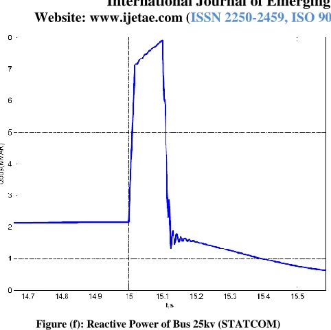
The reactive power is injected to the 25 KV bus via 400 KVar PFC capacitor, which is connected to terminal wind turbines. After fault clearance on t=15.1 sec, reactive power injection decreases. The active power of 25 KV bus power decreases after fault occurrence on t=15 sec and this reduction continues until removal of fault on t=15.1 sec. However, Active power reduction with presence of SVC is more than with presence of STATCOM. In SVC, Reactive power generated is reduced by reduction in voltage profile. The maximum reactive current of STATCOM is independent of network voltage. After t=15.1 sec, active power of bus increases until it reaches to its stable quantity after several swings.
Figure (a): Active power of three pair of wind turbine (SVC)
Figure (b): Reactive power of three pair of wind turbine (SVC)
[image:5.612.54.294.452.643.2]International Journal of Emerging Technology and Advanced Engineering
Website: www.ijetae.com (ISSN 2250-2459,ISO 9001:2008 Certified Journal, Volume 5, Issue 7, July 2015)
301 Figure (d): Rotor speed of three pair of wind turbine (SVC)
Figure (e): Active power of bus 25kv (SVC)
[image:6.612.56.295.115.339.2]Figure (f): Reactive power of BUS 25Kv (SVC)
Figure: Simulation results with PFC and 3MVar SVC (fault applied at 15s and lasted for o.1s)
[image:6.612.328.569.118.348.2] [image:6.612.53.291.350.552.2] [image:6.612.333.570.377.564.2]International Journal of Emerging Technology and Advanced Engineering
Website: www.ijetae.com (ISSN 2250-2459,ISO 9001:2008 Certified Journal, Volume 5, Issue 7, July 2015)
302 Figure (b): Reactive power of three pair of wind turbine (STATCOM)
Figure (c): Rotor speed of three pair of wind turbine (STATCOM)
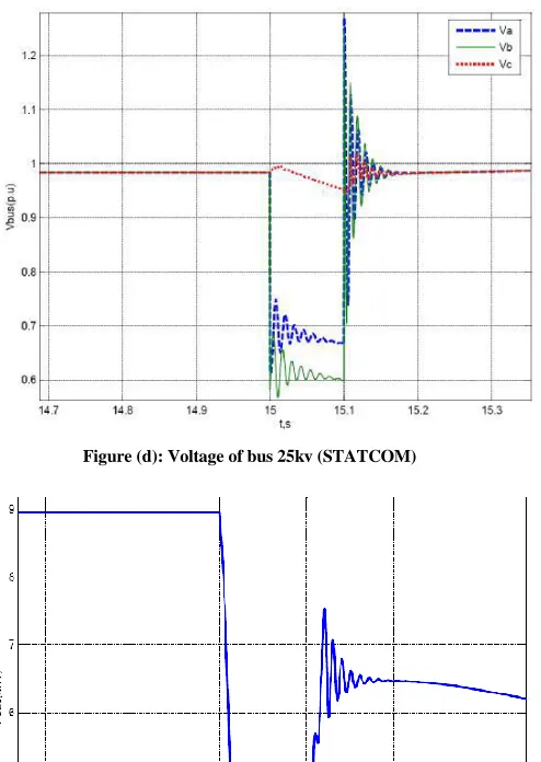
Figure (d): Voltage of bus 25kv (STATCOM)
[image:7.612.54.301.107.329.2] [image:7.612.330.577.131.479.2] [image:7.612.327.573.333.552.2] [image:7.612.55.299.352.554.2]International Journal of Emerging Technology and Advanced Engineering
Website: www.ijetae.com (ISSN 2250-2459,ISO 9001:2008 Certified Journal, Volume 5, Issue 7, July 2015)
[image:8.612.53.294.111.351.2]
303 Figure (f): Reactive Power of Bus 25kv (STATCOM)
Figure: Simulation results with PFC and 3MVar STATCOM (fault applied at 15 sec. and lasted for 0.1sec.)
TABLE.
COMPARISON BETWEEN COMPENSATOR
COMPENSATOR TCR-TSC (SVC) STATCOM
TYPE CONTROLLED
IMPEDANCE
SYNCHRONOUS VOLTAGE SOURCE
LOSSES LOW MEDIUM
HARMONIC LOW VERY LOW
MAXIMUM DELAY 1CYCLE WITHDRAW
TRANSIENT BEHAVIOR OF SYSTEM
MEDIUM GOOD
MAINTENANCE COST MEDIUM MEDIUM
COMPENSATION COST MEDIUM HIGH
V. CONCLUSION
Behavior of both the system on basis of voltage and reactive power flow can be analyze and compare by testing the system equipped with SVC and STATCOM. From reactive power analyzing, it is clear that the reactive power is low in STATCOM.
In a SVC, Maximum capacitive power generated is proportional to the square of the system voltage. While in a STATCOM, Maximum capacitive power generated is decreases linearly with voltage. The ability of STATCOM is to provide more capacitive power during a fault over the SVC. The simulation result shows that the STATCOM exhibits a fast response than SVC because STATCOM has no Thyristor firing delay. So, Simulation result shows that the performance of wind farm stability is better with STATCOM compensation than the SVC compensation during fault occurrence. So, in this Paper, System voltage regulation is effectively carried out to IG based wind farm connected to grid and load by STATCOM.
REFERENCES
[1] M. Ali and B. Wu, ―Comparison of stabilization methods for fixed speed wind generator systems,‖ IEEE Trans. Power Del., vol. 25, no. 1,pp. 323–331, Jan. 2010..
[2] M. Slepchenkov, K. Smedley, and J. Wen, ―Hexagram-converter- based statcom for voltage support in fixed-speed wind turbine generation systems,‖ IEEE Trans. Ind. Electron., vol. 58, no. 4, pp. 1120–1131,Apr. 2011..
[3] C. Han, A. Huang, M. Baran, S. Bhattacharya, W. Litzenberger,L. Anderson, A. Johnson, and A.-A. Edris, ―Statcom impact study on the Integration of a large wind farm into a weak loop power system,‖ IEEE Trans. Energy Convers., vol. 23, no. 1, pp. 226–233, Mar. 2008.
[4] L. Xu, L. Yao, and C. Sasse, ―Comparison of using SVC and statcom for wind farm integration,‖ in Proc. Int. PowerCon , Oct. 2006, pp. 1–7..
[5] M. Molinas, J. A. Suul, and T. Undeland, ―Low voltage ride through of wind farms with cage generators: STATCOM versus SVC,‖ IEEE Trans. Power Electron., vol. 23, no. 3, pp. 1104–1117, May 2008. [6] J. Suul, M. Molinas, and T. Undeland, ―STATCOM-based indirect
torque control of induction machines during voltage recovery after grid faults,‖ IEEE Trans. Power Electron., vol. 25, no. 5, pp. 1240– 1250, May 2010..
[7] C. Hochgraf and R. Lasseter, ―STATCOM controls for operation with unbalanced voltages,‖ IEEE Trans. Power Del., vol. 13, no. 2, pp. 538–544, Apr. 1998.
[8] P. Rodriguez, G. Medeiros, A. Luna, M. Cavalcanti, and R. Teodorescu, ―Safe current injection strategies for a statcom under asymmetrical grid faults,‖ in Proc. IEEE ECCE, Sep. 2010, pp. 3929–3935
[9] P. Rodriguez, A. Timbus, R. Teodorescu, M. Liserre, and F. Blaabjerg, ―Flexible active power control of distributed power generation systems during grid faults,‖ IEEE Trans. Ind. Electron., vol. 54, no. 5, pp. 2583–2592, Oct. 2007.
[10] S. Alepuz, S. Busquets-Monge, J. Bordonau, J. Martinez- Velasco,C. Silva, J. Pontt, and J. Rodriguez, ―Control strategies
based on symmetrical components for grid-connected converters under voltage dips,‖ IEEE Trans. Ind. Electron., vol. 56, no. 6, pp. 2162–2173, Jun. 2009.
[11] A. Luna, P. Rodriguez, R. Teodorescu, and F. Blaabjerg, ―Low voltage ride through strategies for SCIG wind turbines in distributed
[image:8.612.43.295.398.658.2]International Journal of Emerging Technology and Advanced Engineering
Website: www.ijetae.com (ISSN 2250-2459,ISO 9001:2008 Certified Journal, Volume 5, Issue 7, July 2015)
304 [12] C. Wessels, F. Fuchs, and M. Molinas, ―Voltage control of a statcom
at a fixed speed wind farm under unbalanced grid faults,‖ in Proc. 37th IEEE IECON, Nov. 2011, pp. 979–984.
[13] B. Singh, S. Murthy, and S. Gupta, ―Statcom-based voltage regulator for self-excited induction generator feeding nonlinear loads,‖ IEEE Trans. Ind. Electron., vol. 53, no. 5, pp. 1437–1452, Oct. 2006. [14] H. Mahmood and J. Jiang, ―Modeling and control system design of a
grid connected VSC considering the effect of the interface transformer type,‖ IEEE Trans. Smart Grid, vol. 3, no. 1, pp. 122– 134, Mar. 2012
[15] F.W. Koch, L Erlich, ancl F. Shewarega, _Dynamic simulation of large wind farms integrated in a multi machine network, Proceeding of 2003 IEEE power Engineering society general meeting, Toronto, Canada, l3-17 July 2003.
[16] Anaya-Lara, N. Jenkins, J. Ekanayake, P. Cartwright, and M. Hughes, Wind Energy Generation: Modeling and Control. Hoboken, NJ: Wiley, 2009.