BRAIN COMPUTER INTERFACE BASED ROBOT DESIGN
1 Dr V PARTHASARATHY, 2 Dr G SARAVANA KUMAR 3S SIVASARAVANA BABU,
4 Prof. GRIMM CHRISTOPH
1
Vel Tech Multi Tech Dr RR Dr SR Engineering College, Department of CSE, Chennai, INDIA
2,3
Vel Tech High Tech Dr RR Dr SR Engineering College, Department of ECE, Chennai, INDIA
3
Technische Universitat Kaiserslautern, AG Design of Cyber-Physical Systems, Germany.
E-mail: 1 [email protected] , [email protected] ,[email protected]
ABSTRACT
Electro Encephalo Gram based Brain-Computer Interface mobile robots can help as powerful support for severely disabled people in their regular activities, especially to aid them to move voluntarily. This paper proposes and implements a brain signal controlled robot to yield four different directional movements. The schemes uses a single electrode pair acquisition scheme, ARM controller based driving unit and robot module. This paper uses three performance metrics to validate the effectiveness of the scheme. It also exhibits good results in generating different navigational directions in accordance with the driving signal.
Keywords: Electro Encephalo Gram, Brain-Computer Interface, ARM controller, Robot
1. INTRODUCTION
The replacement characteristic of robots is empowering physically challenged human beings to lead their life independently. The upward emerging need for assistive robots is rooted in their ability to perform multiple activities associated with physically challenged people. The main constraint associated with these robots is the inability of the challenged people to feed driving inputs. This limitation is mitigated by implementation of distinct systems driven by physiological signals [2]. The
physiological signals generated by humans
anguishing from amyotrophic lateral sclerosis (ALS), multiple sclerosis (MS) and paralysis. The high degree of disability linked with these patients does not permit them to communicate with these assistive systems via conventional physiological signals. This constraint constricts the efficiency of self-sufficient robots to provide specified position displacement with accuracy. The impact of this failure induces psychological discomfort and stress to the end users [3]. The development of unique category of communication interfaces in addition to the existing assistive systems will equip the patients to establish an effective communication with the external world.
Developments in assistive technology for severely disabled patients, for the past two decades had provided an alternative communication channel between a user’s brain and the external world as,
Brain Computer Interface (BCI). A Brain Computer Interface is a communication system that does not depend on the brain’s normal output pathways of peripheral nerves and muscles. The literature also uses following equivalent terms to refer BCI such as, Brain Machine Interface (BMI), Brain Interface (BI) and direct brain interface (DBI). The effectiveness in using electrical impulses generated in the brain in response to the
presented stimulus to control objects in
environment will determine the efficiency of a BCI system design. Localization of Specific feature in the user’s brain activity which relates his/her intention to communicate and/or control with the external world, will enable to accomplish the same [4]. The electrical activity of brain can be acquired by BCI’s in two broad methods namely invasive and non-invasive. Non Invasive methodology is based on the recordings of Electro Encephalo Graph (EEG) from the surface of the head. It provides solutions for paralyzed people for simple communications with the outside world. In Invasive method electrodes are implanted intra cranially. This methodology provides neural signals of the best quality and has a high potential for further improvement. At the same time, it carries risk associated with an invasive surgical procedure.
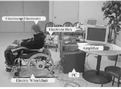
manipulators and mobile robots. Two main classes of brain-controlled robots to assist disabilities are brain-controlled manipulators and mobile robots [1]. A typical brain controlled robot is shown in Figure 1[5]. The brain controlled mobile robot systems are expected to provide high degree of smooth mobility and sensitivity to variations in the driving signal. They should possess lower latency classification time and high precision.
Figure 1: Typical Brain Controlled Robot
This paper implements a brain controlled robot through the following modules, namely
i. Electro Encephala Gram (EEG) acquisition unit
ii. Electrode Signal Processing Connectivity Scheme
iii. EEG processing Algorithm
iv. Control Signal transfer from EEG processing unit to robot module
v. Robot module
2. RELATED WORKS
The core theme of the brain-controlled mobile robot is to endow choice based navigational control capacity and safety of the robot to the user based on their brain signals. An efficient brain signal mapping technique implementation will serve the aforementioned objective. The brain-controlled robots are classified in to two broader categories,
1)robot intelligence techniques in sensing
surrounding situations, localization, path planning, and obstacle/collision avoidances and 2) shared control techniques, combining the BCI with the intelligence of robots to share the control over the robot [6], [7].
2.1 Brain-Controlled Mobile Robots
Based on operational modes brain-controlled mobile robots can be classified “BCI direct control
direct control robots derive commands from EEG signal translation by BCI’s and the second category of robots are manipulated by “shared control scheme” contributed by joint venture between BCI outputs and autonomous navigational controller. A brain-controlled robotic wheelchair was implemented to maneuver in left or right directions. In realistic environments it exhibited an effective EEG mapping scheme [5]. A motor imagery based BCI was employed to implement a brain-controlled robot [8] [9]. It has the ability to navigate in left, right and forward directions. The advantages of aforementioned robots are non-requirement of supplementary robot control
structure, affordable cost and simplified
computational model. They exhibit sizeable amount of efficiency in response generation to user’s instruction. The main limitation of these assistive models is high degree of dependence on non-invasive BCI to produce effective response. The high latency time and low classification rate of non-invasive BCI’s limits the effectiveness of these robots. This enforces the user to apply frequent motor control commands resulting user fatigue.
A BCI based on P300 potential was implemented to drive a wheel chair with eight directions, stop movements. The system was designed to adapt to various users. The statistical knowledge of target
enables to use Bayesian approach based
classification [10]. A self-paced asynchronous BCI driven by single bipolar EEG signal was proposed. A virtual street environment possessed with stopping points and linear classifier was suggested
and the scheme uses Event Related De synchronization (ERD) showed a performance
of 90%, single runs up to perfect maximum [11].
A small robot was wireless controlled by steady-state visual evoked potential (SSVEP)
extraction from acquired EEG signal. The methodology involves ensemble empirical
mode decomposition and EEG acquired from OZ
position. A matched filter demodulator and an amplitude detector were engaged to identify SSVEP related Intrinsic Oscillatory Functions (IOF) [12].
2.2 BCI Shared Control Robots
controller the shared control methodologies can be classified into explicit control and implicit control [1]. One of the implicit approaches is designed with long duration control time for user scheme; obstacle identification based triggering of intelligent controller scheme [20]. Using [20] approach a system with intelligent controller scheme to manage obstacles and corridor movements; Motor imagery based BCI user control scheme [21].
An asynchronous and very low information transfer rate BCI was used to generate control signal equip wheelchair with path planning, collision/obstacle avoidance, voluntary stopping and reach nine destinations. The design was derived from Support Vector Machine and Linear Classifier for ERD [15]. A BCI user control scheme to generate left and right turn movements, timer based forward movements from motor imagery was implemented [18] [19]. A P300 based BCI system was implemented to select a preferred position from a list of predefined location as a driving signal to guide a wheelchair in a known environment. The ability to terminate the movement is derived from ERD signal or fast P300 signal [3]. A Self-reliant system was developed by combining a P300 BCI and navigation system. This system exhibited an ability to drive a wheelchair in an unknown environment [22]. [23] Proposed a Bayesian network based brain-controlled robot consisting of a navigation system capable of identifying the most feasible solution and Error-related EEG signals driven BCI based decision making system. A Safe Wheelchair navigation mechanism was implemented using Steady State Visual Evoked Potential based BCI to traverse in four directions [23].
3. PROPOSED SCHEME
The proposed scheme narrates a methodology to implement a robotic module driven by features extracted from EEG are presented in the following subsections.
3.1 Control Signal Generation Mechanism
3.1.1 Establishing Communication link
between Electrode pair and Computer
1. Port initialization and declaration
2. Variable declaration data_BLINK,
data_ALLOCATION
3. Define and set Communication parameters
TG_Connect() and TG_SetBaudrate
4. Define a variable TG_GetValue()
5. Loading electrode pair dynamic link library with
6. Define a variable connectionId1
7. Define Control Variable for stream log file connection assessment
8. Define Control Variable for data log file connection assessment
9. Define Control Variable to check connectivity status of connection ID handle is connected to serial port COM3 and compliance of parameter benchmark values
10. If
i. Connection status is TRUE
ii. TG_EnableBlinkDetection is TRUE
Then
START EEG acquisition
3.1.2 Attention Lock Assessment Scheme
1. Set Port Connection, Baud rate
2. Initialize four control variable i, j, k, l to zero 3. Set two status variables Blink and Drive mode
to Zero 4. If
Data_ATTENTION is ENABLE then
Increment ‘k’ by 1 Increment ‘i’ by 1
Calculate data_ATTENTION
5. Display(‘ATTENTION=’)
Display (data_ATTENTION (k))
6. Check data_ATTENTION(k)
3.1.3 Maneuvering Scheme
1. Set timer value to 20 Seconds 2. If
Data packet read was enabled and
Eye blink Strength is TRUE Then
Increment ‘j’ by 1
3. Calculate data_BLINK(j)
display ('BLINK = '); display(data_BLINK (j)); 4. If
data_BLINK (j) > 55 then
Increment Blink by 1 5. If
(Blink ==3) Then
Enable drive_mode Assign Blink=0
6. If Drive_mode and Blink is ENABLED
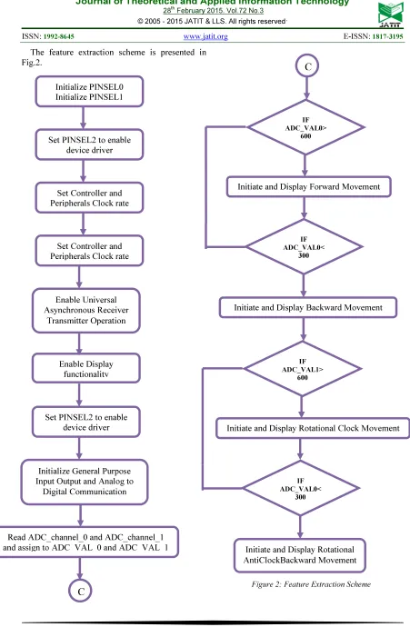
The feature extraction scheme is presented in Fig.2.
Figure 2: Feature Extraction Scheme Initialize PINSEL0
Initialize PINSEL1
Set PINSEL2 to enable device driver
Set Controller and Peripherals Clock rate
Set Controller and Peripherals Clock rate
Enable Universal Asynchronous Receiver
Transmitter Operation
Enable Display functionality
Set PINSEL2 to enable device driver
Initialize General Purpose Input Output and Analog to
Digital Communication
Read ADC_channel_0 and ADC_channel_1 and assign to ADC_VAL_0 and ADC_VAL_1
C
C
IF ADC_VAL0>
600
Initiate and Display Forward Movement
IF ADC_VAL0<
300
Initiate and Display Backward Movement
IF ADC_VAL1>
600
Initiate and Display Rotational Clock Movement
IF ADC_VAL0<
300
4. IMPLEMENTATION
[image:5.595.338.473.407.533.2]Figure 3: Physical Interconnect Layout of Hardware Implementation
[image:5.595.104.261.515.706.2]Figure 4: LPC2148 Microcontroller Board
Figure 5: Hardware Implementation of Proposed Scheme
Figure 6: EEG Acquisition Electrode
The hardware implementations of the
comprehensive robot module are shown in Fig. 4, Fig. 5. The block diagram of the holistic system is shown in Fig. 3 and Fig. 7. The electrical activity of the brain was captured using a single pair electrode as shown in Fig. 6.
Figure 7: Proposed Scheme
5. PERFORMANCE EVALUATION
The metrics identified to evaluate brain-controlled mobile robot systems were task metrics and ergonomic metrics. Task metrics refers to accomplishment of specified tasks by the
brain-controlled robots. The proposed scheme
accomplishes four movements in conventional surface and exhibits a linear relationship with the EEG signal input. The four movement directions are forward, backward, right and left. This scheme was validated against two matrices, Concentration Time Ratio (CTR) and Mission Time Ratio (MTR) yielding values 5 seconds and 8 seconds respectively.
6. CONCLUSION
The objective of brain-controlled mobile robots implementation is to assist and incorporate mobility to patients suffering from debilitating degenerative muscular diseases. This paper proposes and implements a holistic methodology to acquire EEG
signal with simple electrode, hardware
implementation of robot, efficient EEG feature extraction scheme to derive driving signal. The proposed scheme maneuvering ability can be improved to navigate in uneven and obstacle ridden surfaces.
REFRENCES:
[1] Luzheng Bi, Member, IEEE, Xin-An Fan and Yili Liu, Member, IEEE, “EEG based Brain-Controlled Mobile Robots: A Survey”, IEEE transactions on Human Machine Systems,
Vol. 43, No.2, March 2013.
[2] X. Perrin, “Semi-autonomous navigation of an
assistive robot using low throughput
Interfaces”, Ph. D. Dissertation, ETHZ, Zurich,
Switzerland, 2009.
[3] B. Rebsamen, C. Guan, H. Zhang, C. Wang, C. Teo, M. H. Ang Jr and E. Burdet, “A brain controlled wheelchair to navigate in familiar environments”, IEEE transactions on Neural
Systems and Rehabilitation Engineering,
Vol. 18, No. 6, 2010.
[4] J. D. R. Milan, R. Rupp, G. R. Muller-Putz, R.
Murray Smith, C. Giugliemma, M.
Tangermann, C. Vidaurre, F. Cincotti, A. Kubler, R. Leeb, C. Neurper, K. R. Mueller and
D. Mattia, “Combining brain-computer
interfaces and assistive technologies state of the art and challenges”, Frontier Neuroscience, Vol. 4, pp. 1-5, 2010.
[5] K. Tanaka, K. Matsunaga and H. O. Wang, “Electroencephalogram based control of an electric wheel chair”, IEEE transactions on
Robotics, Vol. 21, No. 6, pp.
[6] I. Iturrate, J. M. Antelis, A. Kubler and J. Minguez, “A non-invasive brain actuated wheel chair based on P300 neurophysiological protocol and automated navigation”, IEEE
transactions on Robotics, Vol. 25, No. 3, pp.
614-619, June 2009.
[7] G. Vanacker, J. del R. Millan, E. Lew, P. W. Ferrez, F. G. Moles, J. Philips, H. V. Brussel and M. Nuttin, “Context-based filtering for
brain actuated wheelchair driving”,
Computational Intelligence Neuroscience, pp.
1-12, May 2007.
[8] K. Choi and A. Cichocki, “Control of a wheelchair by motor imagery in real time,” in
Proc. 9th Int. Conf. Intell. Data Eng. Autom.
Learning, 2008, pp. 330–337.
[9] K. Choi, “Control of a vehicle with EEG signals in real-time and system evaluation,” Europen
Journal of Applied Physiology, Vol. 112, No. 2,
pp. 755–766, Jun. 2011.
[10] Pires, M. Castelo-Branco, and U. Nunes, “Visual P300-based BCI to steer a wheelchair: A Bayesian approach,” in Proceedings IEEE
Eng. Med.Biol. Soc., pp. 658–661, 2008.
[11]R. Leeb, D. Friedman, G. Muller-Putz, R. Scherer, M. Slater, and G. Pfurtscheller, “Self-paced (asynchronous) BCI control of a wheelchair in virtual environments: A case study with a tetraplegic,” Comput Intell.
Neurosci., Vol. 2007, pp. 1–7, 2007.
[12]P.-L. Lee, H.-C. Chang, T.-Y. Hsieh, H.-T. EEG ACQUISITION
FEATURE EXTRACTION MODULE
BLUETOOTH MODULE
ROBOT MODULE
small robot car using ensemble empirical mode
decomposition-based approach,” IEEE
Transactions on Systems, Man, Cybernetics,
Vol. 40, No. 5, pp. 1053–1064, Sep. 2012.
[13]B. Rebsamen, E. Burdet, C. Guan, C. L. Teo, Q. Zeng, M. Ang, and C. Laugier, “Controlling a wheelchair using a BCI with low information transfer rate,” in Proc. Conf. Rec. IEEE 10th
Int. Conf. Rehabil. Robot., Noordwijk,
Netherlands, pp. 1003–1008, 2007.
[14]B. Rebsamen, C. L. Teo, Q. Zeng, M. H. Ang Jr., E. Burdet, C. Guan, H. H. Zhang, and C. Laugier, “Controlling a wheelchair indoors using thought,” IEEE Intelligence Systems., Vol. 22, no. 2, pp. 18–24, Mar. 2007.
[15]P.-L. Lee, H.-C. Chang, T.-Y. Hsieh, H.-T. Deng, and C.-W. Sun, “A brain-wave-actuated small robot car using ensemble empirical mode decomposition-based approach,” IEEE Trans.
Syst., Man, Cybern. A:Syst. Humans, vol. 40,
no. 5, pp. 1053–1064, Sep. 2012.
[16]D. Vanhooydonck, E. Demeester, M. Nuttin, and H. V. Brussel, “Shared control for intelligent wheelchairs an implicit estimation of the user intention,” in Proceedings 1st
International Worshop Advanced Service
Robot., Bardolino, Italy, Mar. 13–15, 2003.
[17]H. K. Kim, S. J. Biggs, D. W. Schloerb, J. M. Carmena, M. A. Lebedev, M. A. Nicolelis, and M. A. Srinivasan, “Continuous shared control for stabilizing reaching and grasping with
brain–machine interfaces,” IEEE Trans.
Biomed. Eng., vol. 53, no. 6, pp. 1164–1173,
2006.
[18]T. Geng, J. Q. Gan, and H. S. Hu, “A self-paced online BCI for mobile robot control,”
International Journal of Advanced
Mechatronic Systems, Vol. 2, No. 1/2,
pp. 28–35,2010.
[19]T. Geng, M. Dyson, C. S. Tsui, and J. Q. Gan, “A 3-class asynchronous BCI controlling a simulated mobile robot,” in 29th International
Conference Annual Proceedings 2007
IEEE/EMBS Lyon, France, pp. 2524–2527,
Aug. 2007.
[20]D. J. Bruemmer, D. A. Few, R. L. Boring, J. L. Marble, M. C. Walton, and C. W. Nielsen,
“Shared understanding for collaborative
control,” IEEE Transactions on System ,Man,
Cybernetics A, Vol. 25, No. 4, pp. 494–504,
July 2005.
[21]A. R Satti, D. Coyle, and G. Prasad, “Self-paced brain-controlled wheelchair methodology with shared and automated assistive control,” in
Proc. Conf. Rec .IEEE Symp. Series Comput.
Intell., Paris, France, pp. 120–127, 2011.
[22]I. Iturrate, J. M. Antelis, A. Kubler, and J.
Minguez, “A noninvasive brain-actuated
wheelchair based on a p300 neurophysiological protocol and automated navigation,” IEEE
Trans. Robot., vol. 25, no. 3, pp. 614– 627, Jun.
2009
[23]C. Mandel, T. Luth, T. Laue, T. Rofer, A. Graser, and B. Krieg-Bruckner, “Navigating a smart wheelchair with a brain–computer interface interpreting steady-state visual evoked potentials,” in Proc. Conf. Rec. IEEE/RSJ Int.
Conf. Intell. Robots Syst., St. Louis, MO, pp.
1118–1125.