Technology (IJRASET)
©IJRASET 2015: All Rights are Reserved
157
UPFC Based Wind Energy Efficient System
Hirdesh Chaturvedi1, Abhishek Pachauri2, Gaurav Jain3
1,2,3
Dept. of Electrical Engineering, Samrat Ashok Technological Institute, VIDISHA
Abstract--The rapid growth of wind power systems worldwide will likely see the integration of large wind farms with electrical network that are series compensated stable transmission of bulk power. Using Flexible AC Transmission System (FACTS) devices are considered in order to maintain stability and provide the reactive power requirement of the grid and transfer the maximum power extracted from wind turbine to consumers. This paper presents the complete modeling and real-time simulation of wind turbine driven doubly-fed induction generator (DFIG) which feeds ac power to the utility grid.
Keywords-DFIG, DC Control Link, UPFC, Wind Energy Conversion System (WEBS), Direct Torque Control Technique (DTC)
I. INTRODUCTION
ENVIRONMENTAL pollution and shortage of conventional fossil fuel are the two major concerns which have led to the global emergence of wind energy as an effective means of power production. Wind generating capacities have increased from negligible levels in the early 1990s to more than 50 GW today [1], [2].Electricity generation from wind energy and its integration with power grid is a well-established technology. Wind farms with doubly fed induction generators (DFIGs) are time-tested systems for widely varying wind velocity-based variable speed turbine systems [4]. In India, the total installed capacity of wind power generation is 8754 MW in the year 2008.By the end of 2012, the total installed capacity is going to be reached to 12000 MW according to ministry of new and renewable energy, India and total installed capacity of wind energy is estimated to be more than 160 GW [1-8]. The Unified Power Flow Controller (UPFC) concept was proposed by Gyugyi in 1991. The UPFC was devised for the real-time control and dynamic compensation of ac transmission systems, providing multifunctional flexibility required to solve many of the problems facing the power delivery industry. Within the framework of traditional power transmission concepts, the UPFC is able to control, simultaneously or selectively, all the parameters affecting power flow in the transmission line (i.e., voltage, impedance, and phase angle), and this unique capability is signified by the adjective "unified" in its name.(xx)
Electricity generation from wind energy and its integration with power grid is a well-established technology. Wind farms with doubly fed induction generators (DFIGs) are time-tested systems for widely varying wind velocity-based variable speed turbine systems [4]. Various control schemes have been developed to enhance the performance of wind-sourced DFIG systems, including those for distorted grid conditions, weak area electric power system, etc. [4]–[8]. Liu et al. [7] and Xu et al. [8] have discussed elegant solutions for harmonic suppression in stator circuits using rotor-side converter control. Nian and Song [9] have proposed a modified control scheme to smoothen out the overall active and reactive power output of DFIG under distorted grid voltage conditions. At the same time, in the last couple of decades, solar PV-based power generation has also emerged as a strong option. It is a pollution free, noise free, and maintenance free source of energy with no additional mechanical or rotating assembly. Significant advancements and refined control strategies have been reported in the recent past for large capacity grid-connected PV systems [10], [11]. These systems are generally either two power stage or single power stage. Most of these configurations employ a grid-side voltage-source inverter (VSI).
In the DFIG-based wind energy system, the stator circuit carries the bulk power while the rotor provides the balance power on account of wind speed variation during DFIG’s sub- or super synchronous speed operation. This results in the requirement of lower rating power converters for rotor power conditioning, which is especially attractive in the Mega-Watt range installations of wind energy systems [6]. Unfortunately, the converters used in the rotor circuit are not utilized effectively because of topological and configuration constraints. During operation near the synchronous speed, rotor power is considerably less. Another issue with the conventional wind-DFIG system is that part of the power simply circulates in the machine during its sub synchronous operation. In contrast with the DFIG integrated wind energy source, the inverter driven, inertia less PV-grid interfaces result in complex penetration issues such as poor line voltage profile, reduced dynamic stability, voltage fluctuations, and large injected power variations, etc. [12]–[14]. At the same time, the PV inverter remains idle during the night or during very low solar radiation. Extensive efforts have been made by researchers in the past to overcome the issues associated with both PV and wind energy sources by proposing more advanced and refined control schemes, including their hybrid combinations [2], [3], [15]– [18]. Kellogg
Technology (IJRASET)
©IJRASET 2015: All Rights are Reserved
158
through their individual source converters.With doubly fed induction generators (DFIGs) are time-tested systems for widely varying wind velocity-based variable speed turbine systems [4]. Various control schemes have been developed to enhance the performance of wind-sourced DFIG systems, including those for distorted grid conditions, weak area electric power system, etc. [4]–[8]. Liu et al. [7] and Xu et al. [8] have discussed elegant solutions for harmonic suppression in stator circuits using rotor-side converter control. Nian and Song [9] have proposed a modified control scheme to smoothen out the overall active and reactive power output of DFIG under distorted grid voltage conditions. At the same time, in the last couple of decades, solar PV-based power generation has also emerged as a strong option. It is a pollution free, noise free, and maintenance free source of energy with no additional mechanical or rotating assembly. Significant advancements and refined control strategies have been reported in the recent past for large capacity grid-connected PV systems [10], [11]. These systems are generally either two power stage or single power stage. Most of these configurations employ a grid-side voltage-source inverter (VSI). In the DFIG-based wind energy system, the stator circuit carries the bulk power while the rotor provides the balance power on account of wind speed variation during DFIG’s sub- or super-synchronous speed operation. This results in the requirement of lower rating power converters for rotor power conditioning, which is especially attractive in the Mega-Watt range installations of wind energy systems [6]. Unfortunately, the converters used in the rotor circuit are not utilized effectively because of topological and configuration constraints. During operation near the synchronous speed, rotor power is considerably less. Another issue with the conventional wind-DFIG system is that part of the power simply circulates in the machine during its subsynchronous operation. In contrast with the DFIG integrated wind energy source, the inverter driven, inertia less PV-grid interfaces result in complex penetration issues such as poor line voltage profile, reduced dynamic stability, voltage fluctuations, and large injected power variations, etc. [12]–[14]. At the same time, the PV inverter remains idle during the night or during very low solar radiation. Extensive efforts have been made by researchers in the past to overcome the issues associated with both PV and wind energy sources by proposing more advanced and refined control schemes, including their hybrid combinations [2], [3], [15]–[18]. Kellogg et al. [2] have investigated the sizing of generators in a hybrid system, in which the sources and storage are interfaced at the dc link, through their individual source converter.
II. UNIFIED POWER FLOW CONTROLLER
Technology (IJRASET)
©IJRASET 2015: All Rights are Reserved
159
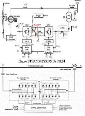
[image:4.612.169.449.293.675.2]reactive power flows on the transmission line. So, this inverter will exchange active and reactive power with the line. The reactive power is electronically provided by the series inverter, and the active power is transmitted to the dc terminals. The shunt inverter is operated in such a way as to demand this dc terminal power (positive or negative) from the line keeping the voltage across the storage capacitor Vdc constant. So, the net real power absorbed from the line by the UPFC is equal only to the losses of the inverters and their transformers. The remaining capacity of the shunt inverter can be used to exchange reactive power with the line so to provide a voltage regulation at the connection point. Block Diagram of detailed model of variable speed wind generator is shown in figure. The model consist of a wind turbine, Wound rotor induction generator, Back to back converter based on two levels of IGBT which are composed of Rotor side converter , Grid side converter, a DC link circuit with a capacitor, DC chopper and two voltage source converter controller. Wind Turbine drives WRIG through a gear box. Stator circuit of WRIG is directly connected to grid system. Back to back converters are connected between the rotor and the grid system. The RSC is connected to the rotor winding of WRIG through slip ring which provides the variable frequency excitation depending on the wind speed condition. The GSC is connected to the grid system via LC filter circuit and a transformer (TR). The DC chopper is installed in the DC-link circuit to protect the circuit during a fault condition. The chopper circuit is triggered when the DC-link voltage exceeds the predefined limit. The RSC is used to control active power output (Pout) and reactive power output (Qout) by regulating the rotor current (Ir). The aim of the GSC is to control the dc Link voltage at constant value and reactive power output of GSC to grid by regulating current output of GSC.
Figure 1.TRANSMISSION SYSTEM
Technology (IJRASET)
©IJRASET 2015: All Rights are Reserved
[image:5.612.212.398.81.201.2]160
[image:5.612.189.424.237.416.2]Figure 3.Power transmission line system
Figure 4.Block diagram of simplified DFIG mode
III. WIND TURBINE DRIVEN DFIG DESCRIPTION
A. Operating principle of wind turbine dfig:
The Power flow illustrated in figure called Power flow is used to describe-
Pm: Mechanical power captured by the wind turbine and transmitted to the rotor, Ps: Stator electrical power output, Pr: Rotor electrical power output Pgc: grid electrical power output, Qs: Stator reactive power output, Qr:Rotor reactive power output,Qgc: grid reactive power output
Tm: Mechanical torque applied to rotor
Tem: Electromagnetic torque applied to the rotor by the generator
Wr: Rotational speed of rotor
Ws: Rotational speed of the magnetic flux in the air-gap of the generator, this speed is named synchronous speed. It is proportional to the frequency of the grid voltage and to the number of generator poles.
J: Combined Rotor and wind turbine inertia coefficient. The mechanical power and the stator electric power output are computed
Pm = Tm.Wr (3)
Technology (IJRASET)
©IJRASET 2015: All Rights are Reserved
161
For a loss less generator the mechanical equation is
JdWr/dt = Tm - Tem (5) In steady-state at fixed speed for a loss less generator Tm = Tem & Pm = Ps + Pr (6)
It follows that:
Pr = Pm - Ps = Tm - Tem
= - Tm Ws (Ws-Wr)/Ws = - s TmWs
= - s Ps (7)
Where s is defined as the slip of the generator:
s = (Ws-Wr)/Ws (8)
IV. SIMULATION RESULTS
The ideal switches and zig-zag phase shifting transformers are used to build a GTO-type 100 MVA, 138 kV voltage source inverters which are used as shunt and series converters in the simulated model. This type of converter is used in high power (up to 200 MVA) Flexible AC Transmission Systems (FACTS) which are used to control power flow on transmission grids. It can be used to build a model of shunt or series static compensator (STATCOM or SSSC) or, using two such converters, a combination of shunt and series devices known as Unified Power Flow Controller (UPFC). This pair of converters can be operated in three modes: *Unified Power Flow Controller (UPFC) mode, when the shunt and series converters are interconnected through the DC bus. When the disconnect switches between the DC buses of the shunt and series converter are opened, two additional modes are available.
*Shunt converter operating as a Static Synchronous Compensator (STATCOM) controlling voltage at bus B1.
*Series converter operating as a Static Synchronous Series Capacitor (SSSC) controlling injected voltage, while keeping injected voltage in quadrature with current are used as shunt and series converters in the simulated model. This type of converter is used in high power (up to 200 MVA) Flexible AC Transmission Systems (FACTS) which are used to control power flow on transmission grids.
[image:6.612.57.554.465.561.2]V. SIMULATION FIG.
Technology (IJRASET)
©IJRASET 2015: All Rights are Reserved
[image:7.612.67.551.80.286.2]162
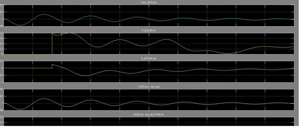
Figure 6.ACTIVE AND REACTIVE POWER
VI. CONCLUSION
As per the simulation model and approach is concerned, the proposed model enhance the efficiency and reduce power losses so can lead to high voltages from wind energy efficient system for 3MG transmission.
VII. FUTURE SCOPE
This is one of the emerging concept in electrical engineering via using renewable sources of energy using UPFC facts device to enhance its workability.
REFERNCES
[1] P. B. Eriksen, T. Ackermann, H. Abildgaard, P. Smith, W. Winter, and J. M. Rodriguez Garcia, “System operation with high wind penetration,” IEEE Power Energy Mag., vol. 3, no. 6, pp. 65–74, Nov./Dec. 2005.
[2] T. Ackerman, Power Wind Power in Power Systems. New York: Wiley, 2005.
[3] J. Yao, H. Li, Y. Liao, and Z. Chen, “An improved control strategy of limiting the DC-link voltage fluctuation for a doubly fed induction wind generator,” IEEE Trans. Power Electron., vol. 23, no. 3, pp. 1205–1213, May 2008.
[4] S. Muller, M. Deicke and R. W. De Doncker, “Doubly fed induction generator systems for wind turbine,” IEEE Industry Applications Magazine, Vol.3, , pp. 26-33.2002.
[5] R. Pena, J. C. Clare and G. M. Asher, “Doubly fed induction generator using back-to-back PWM converts and its application to variable speed windenergy generation,” IEE Proceedings Electrical Power Application, Vol.143, pp. 231-241.1996
[6] A. Tapia, G. Tapia, J. X. Ostolaza and J. R. Saenz, “Modeling and control of a wind turbine driven doubly fed induction generator,” IEEE Transactions on Energy Conversion, Vol.18, pp. 194- 204.2003
[7] Yazhou Lei, Alan Mullane, Gordon Lightbody, and Robert Yacamini, “Modeling of the Wind Turbine With a Doubly Fed Induction Generator for Grid Integration Studies,” IEEE Transactions on Energy Conversion, Vol. 21(1), pp.257-264.2006
[8] V.Akhmatoy and H.Krudsen, “Modelling of windmill induction generator in dynamic simulation programs,” Proc. IEEE Int. Conference on Power Technology, Budapest,Hungary, paper No. 108.Aug 1999.
[9] H.Li and Z.Chen, “Overview of generator topologies for wind turbines,” IET Proc. Renewable Power Generation, vol. 2, no. 2, pp. 123–138, Jun.2008. [10] Lucian Mihet-Popa, Frede Blaabrierg, “Wind Turbine Generator Modeling and Simulation Where Rotational Speed is the Controlled Variable”, IEEE
Transactions on Industry Applications, Vol. 40.No.1, January/February 2004.
[11] B.H.Chowary, Srinivas Chellapilla, “Doubly-fed induction generator for variable speed wind power generation” Transactions on Electric Power System Research, Vol.76,pp. 786-800, Jan 2006.
[12] Understanding FACTS : concepts and technology of flexib transmission systems / Narain G. Hingorani, Laszlo Gyugyi. ISBN 0-7803-3455-8 //
[13] W. Kellogg, M. Nehrir, G. Venkataramanan, and V. Gerez, “Generation unit sizing and cost analysis for stand-alone wind, photovoltaic and hybrid wind/PV systems,” IEEE Trans. Energy Convers., vol. 13, no. 1, pp. 70–75, Mar. 1998.
[14] S. Daniel and N. Ammasai Gounden, “A novel hybrid isolated generating system based on PV fed inverter-assisted wind-driven induction generators,” IEEE Trans. Energy Convers., vol. 19, no. 2, pp. 416–422, Jun. 2004.
Technology (IJRASET)
©IJRASET 2015: All Rights are Reserved
163
IEEE Trans. Power Electron., vol. 23, no. 3, pp. 1205–1213, May 2008.[16] G. Tapia, A. Tapia, and J. Ostolaza, “Proportional-integral regulator-based approach to wind farm reactive power management for secondary voltage control,” IEEE Trans. Energy Convers., vol. 22, no. 2, pp. 488–498, Jun. 2007.
[17] J. Costa, H. Pinheiro, T. Degner, and G. Arnold, “Robust controller for DFIGs of grid-connected wind turbines,” IEEE Trans. Ind. Electron., vol. 58, no. 9, pp. 4023–4038, Sep. 2011.
[18] C. Liu, F. Blaabjerg, W. Chen, and D. Xu, “Stator current harmonic control with resonant controller for doubly fed induction generator,” IEEE Trans. Power Electron., vol. 27, no. 7, pp. 3207–3220, Jul. 2012.
[19] H. Xu, J. Hu, and Y. He, “Operation of wind-turbine-driven DFIG sys tems under distorted grid voltage conditions: Analysis and experimental validations,” IEEE Trans. Power Electron., vol. 27, no. 5, pp. 2354–2366, May 2012.
[20] H. Nian and Y. Song, “Direct power control of doubly fed induction generator under distorted grid voltage,” IEEE Trans. Power Electron., vol. 29, no. 2, pp. 894–905, Feb. 2014.
[21] A. Yazdani, A. Di Fazio, H. Ghoddami, M. Russo, M. Kazerani, J. Jatske vich, K. Strunz, S. Leva, and J. Martinez, “Modeling guidelines and a benchmark for power system simulation studies of three-phase single stage photovoltaic systems,” IEEE Trans. Power Del., vol. 26, no. 2, pp. 1247–1264, Apr. 2011. [22] Z. Dejia, Z. Zhengming, M. Eltawil, and Y. Liqiang, “Design and control of a three-phase grid-connected photovoltaic system with developed maximum power
point tracking,” in Proc. Appl. Power Electron. Conf., Austin, Feb. 2008, pp. 973–979.
[23] S. Eftekharnejad, V. Vittal, G. Heydt, B. Keel, and J. Loehr, “Impact of increased penetration of photovoltaic generation on power systems,” IEEE Trans. Power Syst., vol. 28, no. 2, pp. 893–901, May 2013.
[24] A. Canova, L. Giaccone, F. Spertino, and M. Tartaglia, “Electrical impact of photovoltaic plant in distributed network,” IEEE Trans. Ind. Appl., vol. 24, no. 1, pp. 341–347, Feb. 2009.
[25] M. Bouzguenda and S. Rahman, “Value analysis of intermittent generation sources from the system operations perspective,” IEEE Trans. Energy Convers., vol. 3, no. 2, pp. 484–490, Sep. 1993.
[26] Y. Chen, C. Cheng, and H. Wu, “Grid-connected hybrid PV/wind power generation system with improved DC bus voltage regulation strategy,” in Proc. Appl. Power Electron. Conf. Expo., TX, Mar. 2006, pp. 1088–1094.
[27] F. Nejabatkhah, S. Danyali, S. Hosseini, M. Sabahi, and S. Niapour, “Modeling and control of a new three-input DC–DC boost converter for hybrid