Systems
GA27-2827-15
File No. 5360/5370/53/4300/8100-09
IBM 3270
Information Display System
3274 Control Unit
Planning, Setup, and
Customizing Guide
Configuration Support
A, B, C,
and T
Validation Number 10
Models 1,21,31, and 51C
--...-
-- -- -- --
- - -
--
- .---- ----
-
-~-,-Federal Communications Commission (FCC) Statement
Warning: This equipment generates, uses, and can radiate radio frequency energy and if not installed and used in accordance with the instruction manlial, may cause interference to radio communications. It has been tested and found to comply with the limits for a Class A
computing device pursuant to Subpart J of Part 15 of FCC Rules, which are designed to provide reasonable protection against such interference when operated in a commercial environment. Operation of this equipment in a residential area is likely to cause interference in which case the user at his own expense will be required to take whatever measures may be required to correct the interference.
IBM Statement
This warning is also applicable to all attaching units produced for use in the U.S.A. that have been manufactured after December 31, 1980. A notice of compliance has been affixed within the customer access area of all affected units.
CAUTION
This product is equipped with a UL-listed and
CSA-certified plug for the user's safety.
It
is to
be used in conjunction with a properly grounded
receptacle to prevent electrical shock.
Sixteenth Edition (December 1985)
This minor revision obsoletes GA27-2827-14. Changes or additions to the text and illustrations are indicated by a vertical line to the left of the change.
This publication is for planning only. Changes are made periodically to the information herein; before using this publication in connection with the operation of IBM systems or equipment, consult your mM sales representative or the latest
IBM System/860 Bibliography, GC20-0360, or the IBM System/870 and 4800 Processors Bibliography, GC20-0001, for the editions that are applicable and
current.
References in this publication to IBM products, programs, or services do not imply that IBM intends to make these available in all countries in which mM operates. Any reference to an mM program product in this publication is not intended to state or imply that only mM's program product may be used. Any functionally equivalent program may be used instead.
Publications are not stocked at the address given below. Requests for mM publications should be made to your IBM representative or to the IBM branch office serving your locality.
A form for readers' comments is provided at the back of this publication. If the form has been removed, comments may be addressed to mM Corporation, Department 52Q, Neighborhood Road, Kingston, N.Y." U.S.A. 12401. mM may use or distribute whatever information you supply in any way it believes appropriate without incurring any obligation to you.
C> Copyright International Business Machines Corporation 1977, 1985
-~-~--- - - -
-c
(
(
Preface
This guide is written for customer personnel who are responsible for planning the installation of the IBM 3274 Control Unit.
Organization of Manual
This guide has 7 chapters and 13 appendixes:
• Chapter 1, "Planning Your Installation," provides site planning information for your 3274 installation.
• Chapter 2, "Introduction to Customizing," describes the customizing operation and how and by whom the 3274 customizing procedure is performed.
• Chapter 3, "Preparing to Customize," describes the sequence numbers used in the 3274 customizing procedure. These sequence numbers are associated with functions and features of the 3274 and guide you through the customizing procedure. They are grouped by 3274 model number.
• Chapter 4, "Initial Customizing Procedure," describes how to perform the initial customizing of the 3274.
• Chapter 5, "Modification Procedure," describes how to modify a 3274 configuration without performing the entire customizing procedure.
• Chapter 6, "Backup Diskette Generation Procedures," describes how to generate a backup (duplicate) system or load diskette. You can use this procedure to create a duplicate of your system or load diskette.
• Chapter 7, "Update-Diskette Installation Procedures," describes how to install an update-diskette package in your previously customized 3274.
• Appendix A, "Planning Checklist," provides a suggested checklist to help you plan your installation.
• Appendix B, "3274 Device Cables," provides cable attachment
information, and channel attachment information for the 3274 Models lA, 1B, 1D, 21A, 21B, 21D, 31A, and 31D.
• Appendix C, "Printer Authorization Matrix," describes the printer authorization matrix and how to define it. You will need to refer to this appendix if you wish to use this function.
• Appendix D, "Subsystem Verification Procedure," describes a procedure for verifying the 3274 subsystem after initial microcode load (lML) is performed.
• Appendix E, "Color Convergence Procedure," describes a procedure for converging the color patterns on the 3279 Color Display Station during
customizing. If '''.
'~
• Appendix F, "3274 Communication Cables," provides cabling
information for Models lC, 2lC, 3lC, and 5lC and shows adapters for modem connections.
• Appendix G, "Planning for 3274 Model 3lC Modem Address Switch Settings," tells you how to set the Modem Address switches if you have a 3274 Model3lC with an integrated modem.
• Appendix H, "Planning for 3274 Model5lC Switch Settings," tells you how to set the Transmit Level, Line Speed, or Modem Address switches
if you have a 3274 Model 5lC.
• Appendix I, "3274 Control Storage Requirements," explains how to determine control storage requirements for each model of the 3274.
• Appendix J, "Multiple Interactive Screen Definition-Sequence Number 171," explains how to identify multiple interactive screens using
sequence number 171.
• Appendix K, "Response Time Monitor (RTM) Customizing Information," provides background information and the sequence number 128
description needed to install the response time monitor (RTM) function.
• Appendix L, "Alert Function Customizing Information (Sequence Number 220)," provides the background information needed to install the alert function.
• Appendix M, "Keyboard Layouts for Sequence Numbers 131 through 135 and 166," contains the keyboard diagrams referred to in Chapter 3 for these sequence numbers.
Following the appendixes are a list of abbreviations used in this manual and an index.
.
"
I •
'. -I '",~.-,/
Related Publications
lV
For detailed information about the functions and features of the 3270 Information Display System units, see the latest editions of:
• IBM 3270 Information Display System: Introduction, GA27-2739, which
describes the 3270 hardware units and capabilities, lists programming support, and suggests typical applications
• IBM 3270 Information Display System: 3274 Control Unit Description and Programmer's Guide, GA23-006l, which provides system level
information regarding the functional and programming characteristics of the 3274 Control Unit and attached terminals
(
(
. . .• IBM 3270 Information Display System: Installation Manual-Physical Planning, GA27-2787, which provides physical planning information for
the 3270 units, including floor planning, electrical and environmental requirements, cabling, and machine specifications and descriptions
• IBM 3270 Information Display System: Character Set Reference,
GA27-2837, which provides all the keyboard layouts and input/output interface codes available with the 3270 Information Display System both in the United States and in World Trade countries
• IBM 3270 Personal Computer: Introduction and Preinstallation and Planning, GA23-0179, which provides information for evaluating and
planning the use of the IBM 3270 Personal Computer with the IBM 3274 Control Unit
• IBM 3290 Information Panel Description and Reference, GA23-OO21,
which provides introductory and programming information
• IBM 3270 Information Display System: IBM 3299 Terminal Multiplexer Product Information, G520-4216, which provides information on how the
3299 can be used to reduce the amount of cabling in a 3270 Information Display System installation.
See the IBM 3270 Information Display System Library User's Guide,
GA23-0058, for a complete list of 3270 manuals.
Contents
(
Chapter 1. Planning Your Installation 1·1 Introduction 1·1
System Planning 1·3 Site Preparation 1·3
Communication Services (3274 Models 1C, 21C, 31C, and 51C) 1·4 Local Channel Attachment (3274 Models lA, 1B, 1D, 21A, 21B, 21D, 31A,
and 31D) 1·4
Programming Support 1·6 Response Time 1·6
Configuration Support 1·7
IBM 3270 Personal Computer Compatibility with the 3274 1·9 3290 Compatibility with the Host 1·9
Predelivery Planning 1·10
Installing Your 3274 Subsystem 1·12 Before Equipment Arrives 1·13 After Equipment Arrives 1·14
Replacing a 3271 or a 3272 with a 3274 1·19 Problem Determination Procedures 1·20 Relocation/Removal 1·20
Progress Review 1·20
mM Americas/Far East and mM Europe/Middle East/Africa 1·21 Supplemental Information 1·21
Safety 1·21 Security 1·21
Personnel Training 1·22
Voice Communication between Terminal Operators and Host System Operators 1·22
Chapter 2. Introduction to Customizing 2·1 Subsystem Verification 2·2
3274 Model 31C and 51C Switch Settings 2·3 Preparation for Customizing 2·3
Chapter 3. Preparing to Customize 3·1 3274 Models lA, 21A, and 31A 3·3
001: Keyboard and Customizing Guide Validation 3·3 011: Patch Request 3·3
021: Printer Authorization Matrix 3·3
022: Printer Authorization Matrix Definition 3·4 031: Number of RPQ Diskettes Required 3·4
032: Request RPQ Parameter List (Configuration Support C and T Only) 3·4
111: Number of Category B Terminals (Configuration Support A, B, and COnly) 3·4
112: Number of Category A Terminals 3·5 113: Extended Function Store 3· 7
114: IBM 3270 Personal Computer Attachment (Configuration Support C Only) 3·7
121: Keyboard Language/Character Set I/O Interface Code 3-8
Vlll
127: Response Time Monitor (RTM) Definition (Configuration Support C Only) 3-9
128: RTM Boundaries and Interface Specification (Configuration Support COnly) 3-9
131: Typewriter Keyboard 3-10 132: Data Entry Keyboard 3-10
133: Data Entry Keypunch Layout Keyboard 3-10 134: APL Keyboard 3-10
135: Text Keyboard 3-10
139: 3290 Keypad Selection (Configuration Support T Only) 3-11 141: Magnetic Character Set 3-11
143: Host-Loadable Printer Authorization Matrix 3-11 145: 3289 Print Control 3-11
147: Local-Copy Function 3-12 151: 3274 Model Designation 3-12 161: Color Convergence 3-12 I
162: Structured Field and Attribute Processing (SF AP) (Configuration Support COnly) 3-12
163: Extended Character Set Adapter (Configuration Support C Only) 3-13
164: Programmed Symbols (PS) (Configuration Support COnly) 3-13 165: Decompression (Configuration Support COnly) 3-13
166: Attribute Select Keyboard (Configuration Support COnly) 3-14 170: Distributed Function Terminals (Configuration Support T
Only) 3-14
171: Multiple Interactive Screens (Configuration Support T Only) 3-15 173: 3290 Options (Configuration Support T Only) 3-15
175: 3290 Password (Configuration Support T Only) 3-17
176: BSC Enhanced Communication Option (Configuration Support T Only) 3-17
201: SNA Local Channel Control Unit Address 3-17 211: SCS Support 3-17
213: Between Bracket Printer Sharing 3-17 215: Physical Unit Identification (PUID) 3-17
220: Alert Function (SNA Only) (Configuration Support C) 3-18 301 through 362 3-18
900: Entry Acceptance 3-18 999: Specification Panel 3-18
3274 Models 1B, 1D, 21B, 21D, and 31D 3-19
001: Keyboard and Customizing Guide Validation 3-19 011: Patch Request 3-19
021: Printer Authorization Matrix 3-19
022: Printer Authorization Matrix Definition 3-20 031: Number of RPQ Diskettes Required 3-20
032: Request RPQ Parameter List (Configuration Support C and T Only) 3-20
111: Number of Category B Terminals (Configuration Support A, B, and COnly) 3-20
112: Number of Category A Terminals 3·21 113: Extended Function Store 3-23
114: IBM 3270 Personal Computer Attachment (Configuration Support C Only) 3-23
(--(
(-
..127: Response'Time Monitor (RTM) Definition (Configuration Support C Only) 3-25
128: RTM Boundaries and Interface Specification (Configuration
Support COnly) 3-25
131: Typewriter Keyboard 3-25 132: Data Entry Keyboard 3-26
133: Data Entry Keypunch Layout Keyboard 3-26
134: APL Keyboard (Models 1D, 21D, and 31D Only) 3-26 135: Text Keyboard (Models 1D, 21D, and 31D Only) 3-26 139: 3290 Keypad Selection (Configuration Support T Only) 3-26 141: Magnetic Character Set 3-27
143: Host-Loadable Printer Authorization Matrix 3-27 145: 3289 Print Control 3-27
147: Local-Copy Function 3-27 151: 3274 Model Designation 3-28 161: Color Convergence 3-28
162: Structured Field and Attribute Processing (SF AP) (Configuration Support C Only; Models 1D and 31D Only) 3-28
163: Extended Character Set Adapter (Configuration Support COnly; Models 1D and 31D Only) 3-29
164: Programmed Symbols (PS) (Configuration Support C Only; Models 1D and 31D Only) 3-29
165: Decompression (Configuration Support C Only; Models 1D and 31D Only) 3-29
166: Attribute Select Keyboard (Configuration Support C Only; Models 1D and 31D Only) 3-30
170: Distributed Function Terminals (Configuration Support T Only) 3-30
171: Multiple Interactive Screens (Configuration Support T Only) 3-31 173: 3290 Options (Configuration Support T Only) 3-31
175: 3290 Password (Configuration Support T Only) 3-33
176: BSC Enhanced Communication Option (Configuration Support T Only) 3-33
201 through 362 3-33
900: Entry Acceptance 3-34 999: Specification Panel 3-34
3274 Models 1C, 21C, 31C, and 51C 3-35
001: Keyboard and Customizing Guide Validation 3-37 011: Patch Request 3-37
021: Printer Authorization Matrix 3-37
022: Printer Authorization Matrix Definition 3-37 031: Number of RPQ Diskettes Required 3-38
032: Request RPQ Parameter List (Configuration Support C and T Only) 3-38
111: Number of Category B Terminals (Configuration Support A, B,
and COnly) 3-38
112: Number of Category A Terminals 3-39 113: Extended Function Store 3-41
114: IBM 3270 Personal Computer Attachment (Configuration Support C Only) 3-42
121: Keyboard Language/Character Set I/O Interface Code 3-42
127: Response Time Monitor (RTM) Definition (Configuration Support C Only) 3-42
x
128: RTM Boundaries and Interface Specification (Configuration Support COnly) 3-44
131: Typewriter Keyboard 3-44 132: Data Entry Keyboard 3-44
133: Data Entry Keypunch Layout Keyboard 3-45 134: APL Keyboard 3-45
135: Text Keyboard 3-45
139: 3290 Keypad Selection (Configuration Support T Only) 3-45 141: Magnetic Character Set 3-46
143: Host-Loadable Printer Authorization Matrix 3-46 145: 3289 Print Control 3-46
147: Local-Copy Function 3-46 151: 3274 Model Designation 3-47 161: Color Convergence 3~47
162: Structured Field and Attribute Processing (SF AP) (Configuration Support COnly) 3-47
163: Extended Character Set Adapter (Configuration Support C Only) 3-47
164: Programmed Symbols (PS) (Configuration Support COnly) 3-48 165: Decompression (Configuration Support COnly) 3-48
166: Attribute Select Keyboard (Configuration Support COnly) 3-49 170: Distributed Function Terminals (Configuration Support T
Only) 3-49
171: Multiple Interactive Screens (Configuration Support T Only) 3·50 173: 3290 Options (Configuration Support T Only) 3-50
175: 3290 Password (Configuration Support T Only) 3·52
176: BSC Enhanced Communication Option (Configuration Support T Only) 3-52
201: SNA Local Channel Control Unit Address 3-53 211: SCS Support (SDLC Only) 3-53
213: Between Bracket Printer Sharing (SDLC Only) 3-53 215: Physical Unit Identification (PUID) (SDLC Only) 3-53 220: Alert Function (SNA Only) (Configuration Support C) 3·54 301: Control Unit Number (BSC Only) 3·54
302: SDLC Control Unit Address 3-55 305: BSC Printer Polling 3-56
310: Modem Connection 3-56
311: Modem Wrap (External Modems Only) 3-56 313: NRZI (SDLC Only) or NRZ Encoding 3-56 313: Internal or External Clocking (BSC Only) 3·57 314: Multipoint or Point-to-Point Network 3-57 317: Switched Network Backup (SNBU) 3-57 318: Normal or Half-Speed Transmission 3-57 321: EBCDIC or ASCn Character Set 3-58 331: BSC or SDLC Protocol 3-58
342: Request-to-Send (RTS) Control (2-Wire or 4-Wire) 3-58 343: Communication Interface Options 3-59
345: Answer Tone (Configuration Support C and T Only; World Trade External Switched Network Modems Only) 3-59
347: High-Speed Data Rate (Configuration Support C Only; Loop Attachment Only; Model 51C Only) 3-59
351: HPCA (SDLC Only) or CCA Adapter 3-60
352: Encrypt/Decrypt (SDLC Only) (Configuration Support A, B, and C Only) 3-60
(
(-'~
/
360: X.2l Switched Retry (Configuration Support C; Model5lC Only) (SDLC Only) 3-60
361: X.2l Switched Retry Timing (Configuration Support C; Model 5lC Only) (SDLC Only) 3-60
362: X.2l Switched Options (Configuration Support C; Model 5lC Only) (SDLC Only) 3-60
900: Entry Acceptance 3-61
999: Specification Panel 3-61
Chapter 4. Initial Customizing Procedure 4-1
Chapter 5. Modification Procedure 5-1
Chapter 6. Backup Diskette Generation Procedures 6-1 Backup System Diskette 6-1
Backup Load Diskette 6-2
Chapter 7. Update-Diskette Installation Procedures 7-1 RPQ Update-Diskette Installation 7-1
Language Update-Diskette Installation 7-1
Update-Diskette Installation Procedure for Configuration Support A, B, or C 7-3
Update-Diskette Installation Procedures for Configuration Support T 7-5 Procedure for Updating with New Feature and New System
Diskettes 7-5
Proc:edure for Updating with a New Load Diskette Only 7-7
Appendix A. Planning Checklist A-I
Appendix B. 3274 Device Cables B-1
Instructions for Completing the 3274 Device Cable Attachment Form B-2 3274 Device Cable Attachment Procedure B-3
Appendix C. Printer Authorization Matrix C-l Description C-l
Printer Modes C-l
Printer Class Structure C-2 Source Device Lists C-3 Matrix Structure C-3
Defining the Printer Authorization Matrix during Customizing C-5
Appendix D. Subsystem Verification Procedure D-l
Appendix E. Color Convergence Procedure E-l Operator Instructions E-l
Convergence Procedure E-l Error Conditions E-2
Appendix F. 3274 Communication Cables F-l External ModeIll Cables F-2
3274 Model 5lC with an External Modem Attached to a Switched Line or Models lC, 2lC, 3lC, and 5lC Attached to a Nonswitched Line (All Countries except United Kingdom Datel Modem) F-2
/
Xl!
3274 Model 51C with an External Modem Attached to a Switched Line or
Models 1C, 21C, 31C, and 51C Attached to a Nonswitched Line with a
r".
United Kingdom Datel Modem F-4 "-_;/
Loop Adapter Cable F-6
3274 Model51C with a Loop Adapter Attached to a Loop (All Countries) F-6
X.21 Cable F-7
3274 Model 51C with X.21 Attached to a Switched or Nonswitched Line or Models 1C, 21C, and 31C with X.21 Attached to a Nonswitched
Line F-7
Digital Data Service Adapter Cable F-8
3274 Models 1C, 21C, 31C, and51C with Digital Data Service (DDS) Adapter Attached to AT&T Channel Service Unit (U.S. Only) F-8 Integrated Modem Cables F-9
3274 Models 31C and 51C with an Integrated Modem Attached to a Nonswitched Line (U.S. and Canada Only) F-9
3274 Models 31C and 51C with an Integrated Modem Attached to a
Nonswitched Line (Japan Only) F-10
3274 Model51C with a 1200-BPS Integrated Modem Attached to a Switched Line with Manual Answer (U.S. and Canada Only) F-12 3274 Model 51C with a 1200-BPS Integrated Modem Attached to a
Nonswitched Line with Switched Network Backup (SNBU) and Manual Answer (U.S. and Canada Only) F-13
3274 Model51C with a 1200-BPS Integrated Modem Attached to a Switched Line with Auto-Answer (U.S. and Canada Only) F-14 3274 Model51C with a 1200-BPS Integrated Modem Attached to a
Nonswitched Line with Switched Network Backup (SNBU) and Auto-Answer (U.S. and Canada Only) F-15
3274 Model51C with a 1200-BPS Integrated Modem Attached to a Nonswitched Line with Switched Network Backup (SNBU) and
Auto-Answer (Countries Other Than the U.S. and Canada That Do Not
Use Communication Cable Adapters) F-16
3274 Model 51C with a 1200-BPS Integrated Modem Attached to a Switched Line with Auto-Answer (Countries Other Than the U.S. and
Canada That Do Not Use Communication Cable Adapters) F-17
3274 Model 51C with a 1200-BPS Integrated Modem Attached to a Switched Line with Auto-Answer (Countries Other Than the U.S. and
Canada That Use Communication Cable Adapters) F-18
3274 Models 31C and 51C with an Integrated Modem Attached to a Switched or Nonswitched Line (Countries Other Than the U.S. and
Canada That Do Not Use Communication Cable Adapters) F-19
3274 Models 31C and 51C with a 1200-BPS Integrated Modem Attached to a Switched Line or Any Integrated Modem Attached to a Nonswitched Line (France Only) F-20
Communication Cable Adapters for Countries Other Than the U.S. and
Canada F-21
CCITT V.35 Interface Cable F-23
3274 Models 1C, 21C, 31C, and 51C Attached to a CCITT V.35 Interface F-23
Appendix G. Planning for 3274 Model 3lC Modem Address Switch
Settings G-1
Modem Address Switches (Integrated Modems Only) G-1
Appendix H. Planning for 3274 Model51C Switch Settings H-l Transmit Level Switches (1200 BPS Integrated Modem, U.S. and Canada
Only) H-l
Instructions for Setting 3274 Model5lC Transmit Level Switches (U.S. and Canada Only) H-3
Loop Data Speed Switches (Loop Adapter Feature Only) H-5
Instructions for Setting 3274 Model5lC Loop Data Speed Switches H-6 Modem Address Switches (Integrated Modems with Speeds Greater Than
1200 BPS Only) H-8
Instructions for Setting 3274 Model5lC Modem Address Switches H-9
Appendix I. 3274 Control Storage Requirements 1-1 Models lA, lC, lD, and 5lC 1-1
Models 2lA, 2lC, 2lD, 3lA, 3lC, and 3lD 1-3
Appendix J. Multiple Interactive Screen Definition - Sequence Number 171 J-l
Appendix K. Response Time Monitor (RTM) Customizing Information °K_l
RTM Requirements K-l Host Interface K-l RTM Description K-l
Sequence Number 127 K-2 Sequence Number 128 K-4
Appendix L. Alert Function Customizing Information (Sequence Number 220) L-l
Operator-Generated Alert Message L-l
Appendix M. Keyboard Layouts for Sequence Numbers 131 through 135 and 166 M-l
List of Abbreviations X-I
Index X-3
Figures
XIV
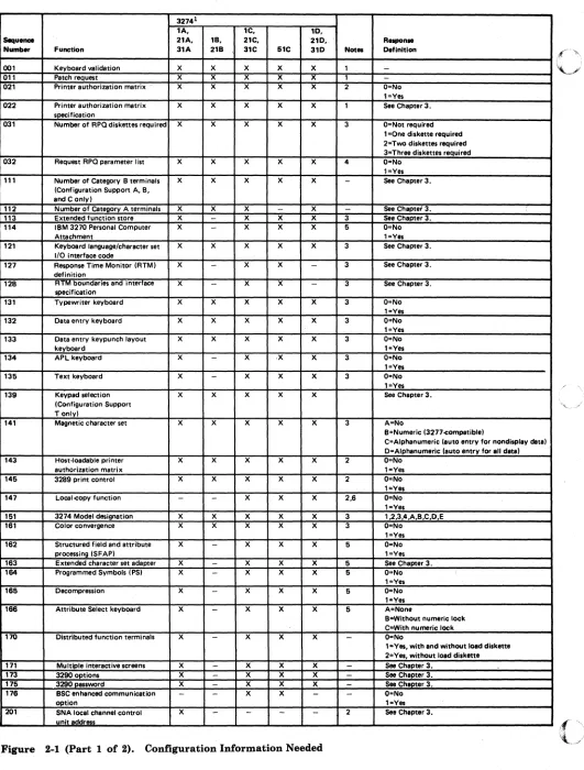
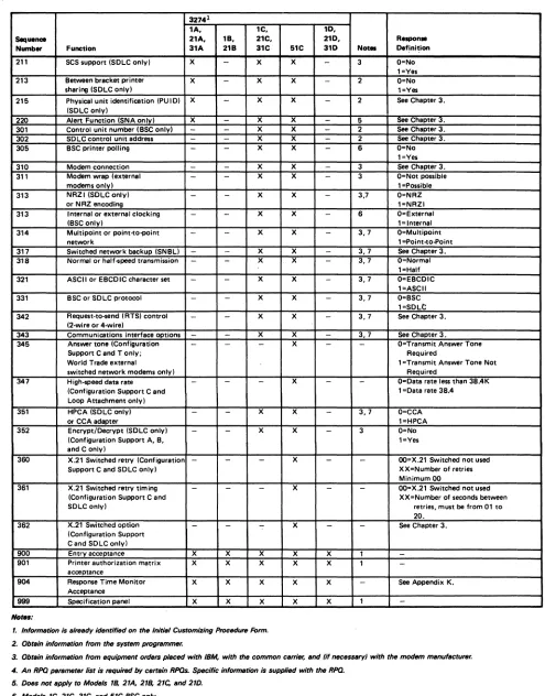
2-1. Configuration Information Needed 2-4
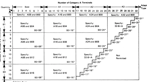
3-1. 3274 Model lA, 2lA, and 3lA Category A and B Terminal Quantity Relationships 3-6
3-2. 3274 Model lA, 2lA, and 3lA Keyboard Language and Character Set
1/0 Interface Code 3-8
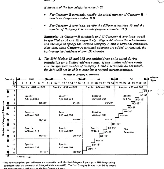
3-3. 3274 ModellB, lD, 2lB, 2lD, and 3lD Category A and B Terminal Quantity Relationships 3-22
3-4. 3274 ModellB, lD, 2lB, 2lD, and 3lD Keyboard Language and Character Set 1/0 Interface Code 3-24
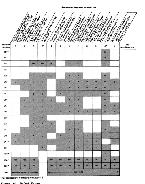
3-5. Default Values 3-36
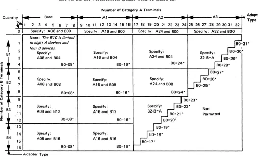
3-6. 3274 ModellC, 2lC, 3lC, and 5lC Category A and B Terminal Quantity Relationships 3-40
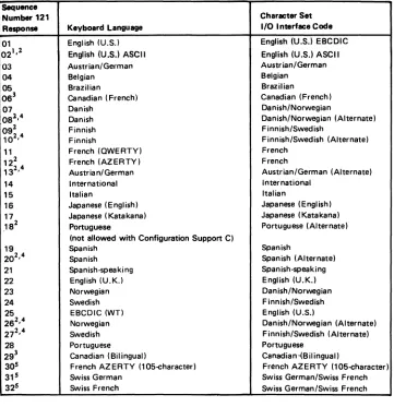
3-7. 3274 ModellC, 2lC, 3lC, and 5lC Keyboard Language and Character Set 1/0 Interface Code 3-43
3-8. BSC Polling Address/Control Unit Number Conversion Chart 3-56 4-1. Valid Key Positions during Customizing 4-9
4-2. Valid Key Positions during Customizing When Japanese Katakana and Japanese English Keyboards Are Used 4-10
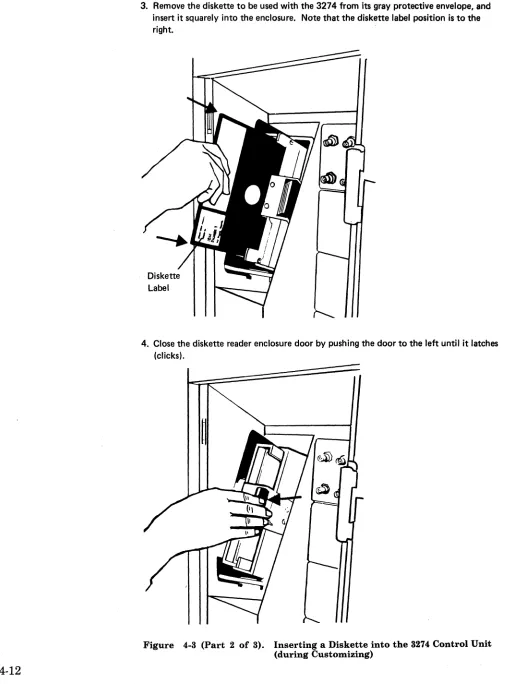
4-3. Inserting a Diskette into the 3274 Control Unit (during Customizing) 4-11
4-4. Operator Codes during Customizing Only 4-14
4-5. Steady 8 4 21 Indicator Codes during Customizing Only 4-16 4-6. Flashing 8 4 2 1 Indicator Codes during Customizing Only 4-17 4-7. 8421 Indicator Codes during IML That May Result from an
Incorrect Customizing Procedure 4-18
5-1. Valid Key Positions during the Modification Procedure 5-9 5-2. Valid Key Positions during the Modification Procedure When
Japanese Katakana and Japanese English Keyboards Are Used 5-10 5-3. Inserting a Diskette into the 3274 Control Unit (during
Modification) 5-11
5-4. Operator Codes during Modification Procedure Only 5-14 5-5. Steady 8 4 2 1 Indicator Codes during the Modification Procedure
Only 5-16
5-6. Flashing 8 4 2 1 Indicator Codes during the Modification Procedure Only 5-17
5-7. 8 4 2 1 Indicator Codes during IML That May Result from an Incorrect Modification Procedure 5-18
6-1. Valid Key Positions during Backup Diskette Generation 6-9 6-2. Valid Key Positions during Backup Diskette Generation When
Japanese Katakana and Japanese English Keyboards Are Used 6-10 6-3. Inserting a Diskette into the 3274 Control Unit (during Backup
Diskette Generation) 6-11
6-4. Operator Codes during Backup Diskette Generation Only 6-14 6-5. Steady 8 4 2 1 Indicator Codes during Backup Diskette Generation
Only 6-16
6-6. Flashing 8 4 2 1 Indicator Codes during Backup Diskette Generation Only 6-17
6-7. 8 4 2 1 Indicator Codes during IML That May Result from an Incorrect Backup Diskette Generation 6-18
(
7-1. 7-2. C-l. C-2. C-3. C-4. C-5. E-l. G-l. G-2. H·l. H-2. H·3.Steady 8 4 2 1 Indicator Error Codes during Update Diskette Procedure 7·9
Flashing 8 4 2 I Indicator Error Codes during Update Diskette Procedure 7·9
Example of a Printer Authorization Matrix C-4
Example of a Completed Printer Authorization Matrix Form C-6 Example of a Printer Authorization Matrix Worksheet (Models lA, lB, lC, lD, 21A, 21B, 21C, 21D, 3lA, 3lC, and 3lD) C-7
Sample Printer Authorization Matrix Worksheet (Models lA, lB, lC, lD, 2lA, 21B, 2lC, 2lD, 3lA, 31C, and 3lD) C-8
Sample Printer Authorization Matrix Worksheet (ModeI5lC) C-9 Examples of Unconverged and Converged Display Screens E-3· Conversion of BSC Control Unit Address and SDLC Control Unit Address to Binary-Equivalent Modem Address Switch Settings on 3274 Model3lC G-2
Example of 3274 Model3lC Modem Address Switch Settings 0-2 3274 Model 51C Transmit Level Switches H·2
Loop Data Speed Switch Settings H-5
Conversion of BSC Control Unit Address and SDLC Control Unit Address to Binary-Equivalent Modem Address Switch Settings on 3274 Model 5lC H·8
H-4. Example of 3274 Model 5lC Modem Address Switch Settings H-8 1-1. 3274 ModellA Control Storage Requirements 1·4
1-2. 3274 ModeIIC/SNA Control Storage Requirements 1·6 1-3. 3274 ModellC/BSC Control Storage Requirements 1·8 1-4. 3274 ModellD Control Storage Requirements 1·10 1-5. 3274 Model 5IC/SNA Control Storage Requirements 1-12 I-S. 3274 Model 3IC/BSC and 5lC/BSC Control Storage
Requirements 1-14
1-7. 3274 Models lA, lC, and lD Extended Function Store Features 1-16 1-8. 3274 Model 5lC Extended Function Store Features 1·16
1-9. 3274 Model 2lA Control Storage Requirements 1·17 1-10. 3274 ModeI2lC/SNA Control Storage Requirements 1-18 1-11. 3274 Model 2lC/BSC Control Storage Requirements 1·19 1-12. 3274 Model 2lD Control Storage Requirements 1-20 1-13. 3274 Model 3lA Control Storage Requirements 1-21 1-14. 3274 Model 3lC/SNA Control Storage Requirements 1-22 J-l. Example of MIS Configuration J-2
J-2. Possible Multiple-Screen Formats J-2 J·3. Possible Multiple-Screen Configurations J-4
J-4. Example of How the 3274 Views MIS Addressing J-5 J-G. Example of How the Host Views MIS Addressing in SNA
Protocol J·6
K-l. Counters and Boundaries K-6
M·l. Example of Typewriter Keyboard M-2 M-2. Example of Data Entry Keyboard M-2
M-3. Example of Data Entry Keypunch Keyboard M-3 M-4. Example of APL Keyboard M-3
M-5. Example of Text Keyboard M-4
M-6. Example of an Attribute Select Typewriter Keyboard M-4 M-7. Example of an Attribute Select Typewriter/APL Keyboard M-5 M-8. Example of a Typewriter Overlay Keyboard M·6
- - - - -~- --~.
Summary of Changes
Sixteenth Edition (December 1985)
• Appendix I has been updated.
• Technical corrections and editorial changes have been made throughout the publication.
Fifteenth Edition (November 1984)
• Customizing information for the 3290 Field Intensify Option has been added to the 3290 Options customizing question (sequence number 173).
• Minor editorial and technical corrections have been made throughout the manual.
• Distributed function terminals (DFTs) are identified at the beginning of Chapter 1.
.Fourteenth Edition (May 1984)
XVI
• Customizing information has been added for the 4250 printer. See sequence numbers 162, 163, and 211.
• The IBM 3270 Personal Computer in distributed function terminal (DFT) mode has been added to the list of DFTs in Chapter 1.
• A copy of the IBM 3274 Configuration Data Card (Configuration
Support: A, B, C, T), GA23-0046, has been added at the end of Chapter 4.
• Chapter 7 has been added to provide the "Update-Diskette Installation Procedures" (engineering changes) for maintenance enhancements.
• Appendix J has been revised to apply to all DFTs.
• Appendix M has been added to provide more information for customizing sequence numbers 131 through 135 and 166.
• An Index has been added.
• Editorial and technical corrections have been made throughout the publication.
(
f··
Chapter 1. J>lanning Your Installation
Introduction
This guide will help you plan the installation of the mM 3274 Control Unit Models lA, 1B, 1C, 1D, 21A, 21B, 21C, 21D, 31A, 31C, 31D, and 51C. These models may be divided into two groups: those that are locally attached via a channel to the host and those that are remotely attached through
communication facilities to the host.
Local-channel-attached models are:
• lA, 21A, and 31A
• 1B and 21B
• 1D, 21D, and 31D.
Remotely attached models are:
• 1C, 21C, 31C, and 51C.
Terminals that can attach to the 3274 Control Unit are divided into two categories, A and B.
Category A terminals are:
• IBM Personal Computer XT /370
• IBM 3270 Personal Computers
• IBM 3178 Display Station Models C1, C2, C3, and C4
• mM 3179 Color Display Station
• mM 3180 Display Station Model 1
•. IBM 3230 Printer Model 2
• IBM 3262 Line Printer Models 3 and 13
• mM 3268 Printer Model 2
• mM 3278 Display Station Models 1 through 5
• mM 3278 Display Station Models 1 through 5 with the IBM 3270 Personal Computer Attachment
• mM 3279 Color Display Station, all models except 2C
1-2
• IBM 3287 Printer Models lC and 2C
• IBM 3287 Printer Models 1 and 2 with 3274/3276 Attachment (feature 8331)
• IBM 3289 Line Printer Models 1 and 2
• IBM 3290 Information Panel (only with 3274 Models 3lA, 3lC, 3lD, and olC)
• IBM 4250 Printer Modell (only with 3274 Models 3lA and 3lD)
• IBM 5210 Printer Models GOI and G02
• IBM 6580 Displaywriter System
Category B terminals are:
• IBM 3277 Display Station Models 1 and 2
• IBM 3284 Printer Models 1 and 2
• IBM 3286 Printer Models 1 and 2
• IBM 3287 Printer Models 1 and 2 with 3271/3272 Attachment (feature 8330)
• IBM 3288 Line Printer Model 2
All models of the 3274, as well as the terminals that connect t9 it, are delivered with unpacking instructions attached to an outside surface of the shipping carton. In addition to the unpacking instructions, the 3274 Models lC, 2lC, 3lC, and 5lC, and all terminals, have setup instructions inside the shipping carton. The unpacking instructions and the setup instructions are step-by-step procedures that describe the unpacking and setup tasks for the unit. Once the 3274 is set up, it must be customized for your unique configuration. Instructions on what you must plan for and how to
customize your 3274 are given in Chapter 2 of this manual.
Note: The term distributed function terminal (DFl') is used in this publication. Current terminals in this category are:
• IBM 3270 Personal Computers
System Planning
( -
Site Preparation
The following tasks should be planned so that they can be accomplished in a timely manner:
• Site preparation for the 3274 subsystem
• Communication facilities preparation for remote attachment of the 3274 Control Unit
• Host system channel preparation for local attachment of the 3274 Control Unit
• Programming support preparation
• 3274 predelivery planning activities.
It may be useful to assign a person in your organization the responsibility of ensuring that all these tasks are planned. The Planning Checklist in Appendix A of this guide contains the events, in a suggested sequence, that should be planned in order to install a locally attached model, and/or to set up a remotely attached model, of the 3274 for the first time; it therefore contains more detail than is required for adding to or replacing an existing subsystem. In either case, each event should be carefully considered so that installation and/or setup is problem-free.
The specifications for the physical requirements of all the attached terminals are given in IBM 3270 Information Display System: Installation Manual-Physical Planning, GA27-2787.
This guide will help you provide compatibility between these units and the following:
• Work-space considerations
• Electrical requirements
• Cable requirements and installation
• Power cord plug requirements
• Environmental requirements.
Communication Services (3274 Models IC, 21C, 31C, and 51C)
Arrangements need to be made for the installation of the communication facilities between the remotely attached models of the 3274 and the host communication unit/adapter. There must be compatibility between the 3274, the modems, the communication line, and the communication unit/adapter; for example, line speed, duplex or half-duplex facilities, and nonreturn to zero (NRZ) or nonreturn to zero inverted (NRZI).
Compatibility among these components is a major consideration. To reduce delays caused by incompatibility, it is recommended that you request assistance from your communication representative and from your IBM representative to determine whether the 3274, modems, communication line, and communication unit/adapter are compatible. In addition, schedules should be established to ensure that the modems, communication line, and communication unit/adapter are installed and tested before delivery of the 3274 and the attached units.
Local Channel Attachment (3274 Models lA, IB, ID, 21A, 21B, 21D, 31A, and
31D)
A plan needs to be established for required changes to your host system selector, multiplexer, or block multiplexer channel configuration.
Considerations should include device priorities, device data rates, device addresses, I/O interface cable lengths, and changes to the sequence and control (power sequencing and emergency power off) cables.
The Channel Attachment Information Form in Appendix B should be completed before the 3274 is delivered. This information will be required by the IBM service representative at the time of installation. The following information will assist you in completing the form. For further
information, see the IBM System/370 Installation Manual-Physical
Planning, GC22-7004. These models may be attached to a byte multiplexer,
block multiplexer, or selector channel. In most cases, the choice of channel attachment depends on system considerations such as channel utilization rather than 3274 operation.
Selector or Block Multiplexer Channel (Non-Byte Mode Operation)
1-4
If you choose to attach these models to a block multiplexer or selector channel, the following options should be selected:
• Select the lOO-kb data rate (for the A models only).
• Select burst mode for the A models. No selection is required for the B and D models.
• Select the priority that will produce the greatest channel efficiency with other attached devices. Factory wiring of high priority is recommended.
l \
i,.J
\.
The 3274 Models A, B, and D are designed to operate with disconnect command chaining (DC C). Depending on the processor being used, maximum channel utilization can be gained by proper specification of the unit control word (UCW) in the host. Consult your IBM systems engineer to find out whether a shared or nonshared UCW should be specified. Also, see the latest version of the IBM System/370 Input/Output Configurator,
GA22-7002.
Byte Multiplexer Channel (Byte Mode Operation)
If you choose to attach these models to a byte multiplexer channel, the following selections should be made:
• Select the correct mode as follows:
Select byte mode for the A models.
Select burst mode for the Band D models only if the 3274 is the only device on the channel. In all other cases, select byte mode.
• Select a priority that is below all overrunnable devices on the channel. This can be accomplished by channel cabling between devices and/or the channel priority options.
• On the A models, select the data rate that will produce maximum channel utilization with other devices attached to the same channel. There is no data rate selection option on the Band D models.
When choosing a control unit address for the A models of the 3274, you may use anyone of the 256 possible addresses.
The Band D models are very similar to the 3272. The hexadecimal (hex) address of the control unit must be a multiple of hex 10 (hex 00, hex 10, hex 20, etc.). If more than 16 devices are attached, the control unit address must be a multiple of hex 20 (hex 00, hex 20, hex 40, etc.).
The B and D models also require an address range. Calculate the number of contiguous addresses as follows:
8 x Number of Type A Terminal Adapters
+
4 x Number of Type B Terminal Adapters
For example, a control unit address of hex 20 with two Type A Terminal Adapters and three Type B Terminal Adapters would be 16
+
12 = 28. Therefore, 28 is the number of contiguous addresses. The 3274 Band D models will then respond to addresses hex 20 through hex 3B.Programming Support
Response Time
1-6
It is important to plan for proper programming support at the host system.
The 3274 clusters can be added to most 3270 display/printer systems with minimal impact on the existing programs. In certain cases, however, host system definition (SYSGEN) parameters will have to be changed to accommodate attachment of a 3274 cluster. Information on programming requirements is given in IBM 3270 Information Display System: 3274 Control
Unit Description and Programmer's Guide, GA23·0061.
In addition, it is recommended that for 3274 clusters you enhance your system availability and serviceability by installing the online test executive program (OLTEP) at the host system. Contact your IBM representative for information about OLTEP.
For IBM 3270 Personal Computers attached to the 3274, the file transfer program can be used to send and receive files between a personal computer session and a host virtual machine/conversational monitor system
(VM/CMS) VM/SP 2.1 or time sharing option (TSO) session. Before either program can be used, the IBM host·supported file transfer program, 5664·281 for VM/CMS or 5665·311 for TSO, must be installed at the host site.
The response time (performance/throughput) of the terminals (displays and printers) attached to a 3274 can be significantly affected by many factors. Some of these factors are:
• Inbound and outbound message lengths
• Frequency and content of message (tabbing, modified data tags [MDTs], selects, and so on)
• Type of channel and size of processing unit
• Protocol (systems network architecture [SNA] or non·SNA; binary synchronous communication [BSC] or Synchronous Data Link Control [SDLC])
• Cluster size, network content, and line speed
• Printer speed and type (with or without intelligence, matrix or line printing, LUI, LU2, or LU3 mode, and with or without color option)
• Screen size and features (Programmed Symbols [PS], color, and so on)
• The associated system control and application programs.
To help you to determine response time during the early planning stages of your 3274 display/printer subsystem, it is recommended that you contact your IBM sales representative. He has the tools and facilities to evaluate your 3274 subsystem response time.
- - - -
Configuration Support
Multiple levels of diskettes (configuration-support levels) are available for the 3274 Control Units discussed in this guide. These levels allow selection of the diskettes (feature, system, and load) that will satisfy your
requirements.
To update your 3270 system with additional functions, you may have to change your configuration-support level. Consult your IBM representative for specific functions included in each configuration-support level.
When new function is added to a configuration support, IBM sends its customers, at their request, an update-diskette package. The
Update-Diskette Installation Procedures for new functions and maintenance
enhancements are in Chapter 7.
Note: Maintenance enhancement for a particular configuration support can be applied only to a control unit that is customized for the same configuration support.
Configuration Support A
Configuration Support A is shipped unless Configuration Support B, C, or T is specified. It is the base level of 3274 support, including base color on attached terminals, plus support for solicitation of summary maintenance statistics from a 3274 Model lA, 2lA, 3lA, lC/SNA, 2lC/SNA, 3lC/SNA, and 5lC/SNA through the use of Network Problem Determination Application (NPDA).
Configuration Support B (Not Available for Models IB and 2lB)
Configuration Support B provides support for all 3270 functions included in Configuration Support A, plus the ability to attach 3278 Display Station ModeI5's, and support for the following functions:
• Pacing of inbound message traffic (Models lA, 2lA, 3lA, lC/SNA, 2lC/SNA, 3lC/SNA, and 5lC/SNA)
• Automatic session recovery in both single- and multidomain networks (IC/SNA, 2lC/SNA, 3lC/SNA, and 5lC/SNA)
• Host notification of changes in the power on/off status at attached terminals (Models lA, 2lA, 3lA, lC/SNA, 2lC/SNA, 3lC/SNA, and 5lC/SNA).
•
Configuration Support C (Not Available for Models lB, 2lA, 2lB, 2lC, and 2lD)
Configuration Support C provides support for all 3270 functions included in Configuration Support B plus support for the following additional
functions:
• Structured Field and Attribute Processing (SF AP) (extended binary-coded decimal interchange code [EBCDIC] only)
• Programmed Symbols (PS) on attached terminals
• Extended Color on attached terminals
• Extended Highlighting on attached terminals
• Decompression of PS load data
• BSC text blocking
• Ability to attach 3278 Model 5 or 3180 Model 1 emulating a 3278 Model 5
• X.2l switched network operation (SNA/SDLC Model 5lC only)
• 3274 entry assist RPQ
• Response time monitor (RTM) (Models 3lA, C, D, and 5lC only)
• Alert function (Models 3lA, 3lC/SNA, and 5lC/SNA only)
• BSC transparency
• Switched network operation (SNA/SDLC Model 5lC only)
• Integrated modems (Models 3lC and 5lC only)
• Loop attachment (SNA/SDLC Model5lC only)
• IBM 3270 Personal Computer Attachment
• IBM 4250 Printer Attachment (Models lA, lD, 3lA, and 3lD only).
Configuration Support T (Not Available for Models lB, 2lA, 2lB, 2lC, and 2lD)
1-8
Configuration Support T provides support for the 3290 Information Panel in addition to the other 3270 functions and terminals except:
• Category B terminals
• 3279 Extended Color models
•
Structured Field and Attribute Processing (SF AP)•
Programmed Symbols (PS) . .'-I I
I,
(
('
•
Loop Adapter•
X.21 Adapter•
Encrypt/Decrypt•
Entry Assist•
4250 Printer Attachment•
Alert function•
Response time monitor (RTM). Encrypt/Decrypt Feature (3274 Models 1C, 21C, 31C, and SIC)It is the customer's responsibility to install a copy of the secondary logical unit (LU) key (the terminal master key) in the 3274 Control Unit equipped with Encrypt/Decrypt (feature 3680). This should be done by someone in a position of trust, such as a security officer. Once the terminal master key has been installed in the 3274, the 3274 generates a verification pattern based on the terminal master key. A master-key verification procedure can be performed by any operator without compromising the security of the Encrypt/Decrypt feature. A mercury battery, mM Part 1743456, is installed in the 3274 to sustain the terminal master key when the 3274 power is off. Replacing this battery, or its equivalent, is also a customer responsibility. Procedures to install and verify the terminal master key, and to replace the mercury battery, are described in IBM 3274 Control Unit User's Guide,
GA27-2850.
Refer also to IBM Cryptographic Subsystem Concepts and Facilities,
GA22-9063, for background information, and to IBM 3270 Information Display System: 3274 Control Unit Description and Programmer's Guide,
GA23-0061, for programming information.
IBM 3270 Personal Computer Compatibility with the 3274
If any IBM 3270 Personal Computers are included in the subsystem, obtain a copy of the Information Worksheet that is used for customizing the IBM Personal Computer system diskette. Make sure that the information on this worksheet agrees with the responses given to the sequence numbers during 3274 customizing. Refer to IBM 3270 Personal Computer
Introduction and Preinstallation Planning, GA23-0179, for more information.
3290 Compatibility with the Host
If any 3290 Information Panels are included in the subsystem, check whether setup level 3 changes are required to make the 3290s compatible with their definition at the host. If so, after customizing is completed and an initial microcode load (IML) of the system has been performed, it may be necessary to set the control unit offline before switching on the 3290. Otherwise, errors may occur when the host tries to communicate with the 3290.
Predelivery Planning
Local Channel Cables
Communication Cable
The local channel-attached models of the 3274 are installed by an mM service representative .. The remotely attached models, on the other hand, are set up by your personnel. To prevent delays and help ensure a
smoother installation/setup, it is recommended that a designated person in your organization:
1. Compile the installation-dependent information described in this section.
2. Distribute the installation-dependent information to the appropriate personnel or to the IBM service representative.
3. Coordinate the activities of your personnel and/or the IBM service representative.
The I/O interface and power sequencing cables between a 3274 and a local channel will be installed and connected by IBM. However, these cables must be ordered by cable order unless you are replacing a 3272 with a 3274, in which case, the same cables can be used.
The communication cable that connects the remotely attached 3274 to the modem or channel service unit is delivered with the 3274. This cable is connected to the 3274 by the setup personnel. Instructions for connecting the communication cable to the 3274 are provided by the 3274 Setup Instructions delivered with these models. Connection to the modem or channel service unit is described in Appendix F.
System Grounding fora Remotely Attached 3274
1-10
Frame ground (EIA RS232 or CCITT V.28 pin 1) and signal ground (EIA RS232 or CCITT V.28 pin 7) should be connected together at one point only. This can be either in the 3274 or in the modem or channel service unit. It is recommended that, if possible, this connection be made in the modem or channel service unit.
In Europe/Middle East/Africa countries, the majority of modems do not have this connection made. For this reason, connection has been made within the remotely attached 3274 models at the plant of manufacture.
Note: If you are replacing a 3271 or 3275 with a 3274 Model1C, 21C, 31C, or
51 C, the modem should already have signal ground and frame ground connected together. However, this should be verified with your
communication supplier.
Fan-Out Feature: This feature permits two or more control units to be
connected to a single modem. If the modem has this capability, it is imperative that the signal ground and frame ground wires be connected together in the modem.
---3274 Device Cables
The device cables are the coaxial cables that connect the 3274 to its attached display stations and printers either directly or via the IBM 3299 Terminal Multiplexer. These cables should be procured and installed before the delivery of the 3274 and of the units that will be attached to the 3274. Your personnel (or contractor) will connect these cables to the 3274 and to the attached terminals.
Note: If you are replacing a 3271 or a 3272 with a 3274, you can use the existing device cables between the 3271/3272 and the attached units. However, the 3271 or 3272 device cables must be
connected/disconnected by an IBM service representative, because the 3271 and 3272 and the attached units do not have customer access areas. It is recommended that, before the IBM service representative disconnects these cables, you have the cables marked as described below.
To reduce delays associated with connecting these cables to the 3274, it is recommended that each cable be marked at both ends to identify:
• The 3274 connector panel type (Category A panels or Category B panels) and the 3274 port (0 to 31) to which it is to be connected
• The unit type of the terminal to be attached.
For additional information concerning device cables, refer to IBM 3270 Information Display System: Installation Manual-Physical Planning,
GA27-2787.
IBM 3299 Terminal Multiplexer
The IBM 3299 Terminal Multiplexer provides improved flexibility in the installation of a 3270 Information Display System by reducing the amount of coaxial cabling required in an installation.
IBM 3270 Information Display System terminals are usually connected to the 3274 Control Unit by coaxial cables. In some installations, available space for these cables runs out as the number of terminals installed grows. The 3299 attaches up to eight terminals. A single cable is used between the 3299 and the 3274 Control Unit, thus saving significant amounts of coaxial cable.
The 3299 will be of interest primarily to customers installing newly acquired 3270 systems, expanding existing systems, or relocating large numbers of 3270 terminals. The 3299 will normally be installed at about the same time that coaxial cabling is installed.
For details about the 3299, see IBM 3270 Information Display System: IBM 3299 Terminal Multiplexer Product Information, G520-4216.
Device Cable Attachment Forms
A 3274 Device Cable Attachment Form is provided in Appendix B ohhis guide to help simplify marking and connecting the cables. Instructions for completing all portions of the form except Network Addresses and for using the form are also included in Appendix B. A form should be completed for each 3274 cluster you order. Copies of the completed form should be given to the personnel who will install and mark the cables and to the personnel who will connect the cables to the 3274. In addition, a copy of the form should be stored in the pocket inside the 3274 customer access door for future reference.
Network Address Labels
Hexadecimal address labels (IBM Part 1743290) are delivered with the 3274. (They will be found, together with an IBM 3274 Control Unit Problem Report Form, GX23-0203, and IBM 3274 Control Unit Configuration Data Card (Configuration Support: A, B, C, T), GA23-0046, in the pocket inside
the 3274 customer access door. On the Model 51C they are in the diskette storage area on the front of the machine.) After each terminal is set up, the label that specifies the terminal's network address should be attached to the address label holder on the terminal (if present).
It is recommended that a designated person in your organization (1) obtain the network addresses from the system programmer, (2) enter the addresses in the Network Address column of the 3274 Device Cable Attachment Form in Appendix B, and (3) distribute the address information to the person who will attach the address labels.
For information concerning SNA network addresses, refer to Systems Network Architecture General Information: Network Addresses, GA27-3102;
for information concerning BSC network addresses, refer to IBM 3270 Information Display System: 3274 Control Unit Description and Programmer's Guide, GA23-0061.
Installing Your 3274 Subsystem
1-12
When your subsystem arrives and you are ready to install the equipment, you will need some information that is packaged with the various
Before. Equipment Arrives
(
D
Prepare the physical location.3274 Control Unit Planning, Setup, and
Customizing Guide
..
-GA27-2827
3270 Installation Manual - Physical Planning
GA27-2787
3274 Device Cable Attachment Form
Appendix B
Unit Site Planning and Preparation Guides
fJ
Prepare installation-unique information.3274 Control Unit Planning, Setup, and Customizing Guide
GA27-2827
...
-
To Physical Installation PersonnelInstructions for 3274 Model51C Switch Settings
,...----...&.---...,
Appendix HInstructions for 3274 Model31C Switch Settings
, . . . - - - -... - - - - , Appendix G
Backup Diskette Form
Chapter 6
Printer Authorization Matrix Form
Initial Customizing Procedure Form
Chapter 4
Chapter 4
Mter Equipment Arrives
Note: Each unit has a Problem Determination Guide packaged with it. If a problem arises while you are setting up a particular component, consult the guide for that component before calling IBM.
II
Unpack and set up the display terminals.-Display
II
Unpack and set up the printers.Unpack Instructions
(
Table-Top Printer
Lift carton
Floor-Standing Printer
1-14
Setup Instructions
Setup Instructions
Setup Instructions
t
I. 1
/-!
-"<-\ j
,
I
(
• Unpack and set up the 3274 Control Unit.
Note: Because special skills and tools are needed to set up A, B, and D models, call your IBM service representative after your personnel
have unpacked and placed the unit.
Your personnel should continue at step 06 when the IBM service representative completes the setup.
3274 Control Unit All Models except 51 C
Setup Instructions
GA27-2866
Lift carton
I
CE Info"""r-
-1
~
3274 Control Unit Model51C
Unpack Instructions'
and Contents List (Retain for IBM Service Representative)
I
--\
(
(Retain for IBM Service
I I
Representative)o
--o
Setup Instructions
GA23-0047
II
Connect the tertninals.3214 contfO\ Unit
A\\ Mode\s e)(cept 6'\C
3214contfO\ unit
Mode\ 6'\C
1-16
port p.O
,e(
(
(
II
Supply customizing information.Backup Diskette Form· Instructions for 3274 Model 31C or 51C
Switch Settings· Subsystem Verification Procedure
IBM 3274 Configuration Data Card (Configuration
.S::~~~12:.oC4f
T)r
Printer AuthorizationI
Matrix Form·3274 Control Unit Planning, Setup, and
Customizing Guide ~ ________ .!""'I 8 4 2.1 Indicator Codes _ _ _ _ ... ~To
Customizer GA27-2827 Diskette Insertion
Diagram Keyboard Diagrams Initial Customizing Procedure Form· Color Convergence Procedure *From Step
fJ
Verify the validation numbers.
System Diskette
Feature Diskette
The number on the form must be
equal to or greater than the number on the diskette.
II
Customize the 3274 Control Unit ..3274 Control Unit All Models except 51C
3274 Control Unit Model51C
1m
Press ·the IML pushbutton on the control panel.3274 Control Unit All Models except 51C
r---...
c
o
IML pushbuttonII
Perform subsystem verification.Note: Go to Appendix 0 in this manual.
II
Set the 3274 Model31C or 51C switches.Note: Go to Appendixes G and H in this manual.
3274 Control Unit Model31C
c
o
1·18
3274 Control Unit Model51C
3274 Control Unit Model51C
-I
I·
!
(
Replacing a 3271 or a 3272 with a 3274
When a 3272 is replaced by a local channel-attached model of the 3274, the existing 3272 local channel attachment and device cables (coaxial cables between the 3272 and its attached units) can be used with the 3274.
However, if the existing 3277/3284/3286/3288 units are to be attached to the 3274, the device addresses of these units have to be changed. For
information concerning device addresses for the 3274 cluster, refer to IBM 3270 Information Display System: 3274 Control Unit Description and
Programmer's Guide, GA23-0061.
The 250V watertight plug used on the '3272 is not compatible with the 3274 waterproof plug. Therefore, when a 3272 is replaced by a 3274, the power receptacle must be changed prior to installation of the 3274. See IBM 3270 Information Display System: Installation Manual-Physical Planning,
GA27-2787, for the type required.
When a 3271 is replaced by a remotely attached model of the 3274, the existing 3271 device cables and modem can be used with the 3274. However, the device addresses of the existing 3277/3284/3286/3288 units and the communication cable that connects the 3271 to its modem cannot be used with the 3274. A new communication cable is delivered with the 3274.
If the existing 3271 or 3272 device cables are to be used with the 3274, it is recommended that the cables be marked as described under "3274 Device Cables."
Notes:
1. The 3277 keyboards and operator ID card readers can be used only with the 3277 Display Station.
2. The 3274, when operating in BSC mode, functions as a 3271 Control Unit, but is not compatible with the 3275 Display Station.
When a 3271 or a 3272 is replaced by a 3274, the following should be considered:
• The 3274 can control up to sixteen 3277s/3284s/3286s/3288s. Therefore, more than one 3274 is required to replace a 3271 or 3272 that has more than 16 of these units attached.
• The 3274 needs a 3178, 3179, 3180, 3278,or 3279 attached to port AO.
Note: All the 3271 or: 3272 device cables must be connected/disconnected by an IBM service representative, because the 3271 or 3272 and the attached units do not have customer access areas.
- - - - _ . _ . _ -... _--_ .... __ ... .
Problem Determination Procedures
The problem determination procedures will help you perform problem determination with minimal reliance on the host system. These procedures use tests contained in the terminals. See IBM 3270 Information Display System Library User's Guide, GA23-0058, for a list of problem determination
manuals.
The procedures enable you to determine whether a problem is being caused by a cluster unit, a system unit or function outside the 3274 cluster, or an operator error. You will also be able to determine whether:
• Operation in a degraded mode is possible
• Useful work can be done until the problem is corrected
• The repair action can be scheduled for deferred maintenance.
If you require the help of an IBM service representative, the error message and error condition information should be recorded on a problem report form for the failing unit before the service representative is called. This information will help the service representative resolve the problem as soon as possible.
Relocation/Removal
To ensure proper handling and/or shipping of the 3274 and the attached terminals when the units are removed or relocated to a different room, building, or mailing address, it is recommended that you call your local mM branch office. Your IBM representative will supply you with the necessary information and can order the required materials.
Note: The help of an IBM service representative is required to relocate a local channel-attached 3274.
Progress Review·
1-20
To ensure a smooth installation and/or setup of the 3274 and attached terminals, it is recommended that approximately two months before delivery of the units you and the mM representative review (1) the progress (or the schedule associated with the changes) at the host system site, (2) the communication network and modems, (3) the physical changes needed at the cluster site, and (4) the progress of the predelivery planning tasks. At the same time, you and your IBM representative can review the cluster configuration to determine whether the feature mix is adequate.
It is also recommended that about two weeks before delivery of the units a designated person in your organization and the setup personnel review the setup instructions with your mM representative.
----.~---.-
-(
.-_."
..IBM Americas/Far East and IBM Europe/Middle
East/Africa
The predelivery/setup responsibilities and procedures for the 3274 Models IC, 21C, 31C, and 51C, and for attached display stations and printers, are the same for U.S. installation and for installation in countries served by IBM Americas/Far East and IBM Europe/Middle East/Mrica.
If you need IBM publications in languages other than English, ask your IBM representative. The IBM representative can provide information concerning the availability of translated IBM publications.
Supplemental Information
Safety
Security
The 3270 units are listed by the Underwriters Laboratory. Exposed
hazardous voltages are not present at the designated customer access areas of the units.
DANGER
Your personnel should be warned not to go beyond the
customer access areas, because there are hazardous
voltages within the areas designated for trained
personnel only.
Electrical grounding of the 3274 and of all the attached units is essential for safety. Be sure that all the facility power receptacles are properly grounded and will accept a grounding type plug (3-prong or equivalent). If
you have any questions about the grounding of power receptacles, contact an electrician. For information about power cord plugs, power receptacles, and other safety considerations, refer to IBM 3270 Information Display System: Installation Manual-Physical Planning, GA27-2787.
If the 3274 and the attached units have access to proprietary records or personnel records, it is recommended that you implement appropriate safeguards for the security of the information and the units. In addition to safeguards that you may develop, accessories such as the Magnetic Hand Scanner and the Magnetic Slot Reader may be available for attachment to your display stations. Also available with the remotely attached models of the 3274 is an Encrypt/Decrypt feature that enhances data security in an SNA-communication environment.
Personnel Training
If you intend to provide formal training for your operators, you may wish to
~-'"
use the operator's guides and problem determination guides that are ,--"" available for your units. See IBM 3270 Information Display System LibraryUser's Quide, GA23-0058, for a list of the manuals appropriate to your
installation.
Voice Communication between Terminal Operators and Host System
Operators
1-22
It is recommended that a telephone be available at each location to allow the 3274 cluster operators to talk with the host system operators. This will assist the operators in performing the problem determination procedures as well as the daily work.
(
·Chapter 2. Introduction to Customizing
Once installation of your 3274 Control Unit is completed as shown in the appropriate "Setup Instructions" and the device cables are connected, you are ready to configure your system of displays and printers. The 3274 Control Unit permits you, the user, to specify the configuration under which your 3274 operates; that is, you customize your 3274 subsystem. The configuration information is stored on a diskette mounted inside the 3274 and enables the 3274 to control all the terminals attached to it. This diskette, delivered with the 3274, also contains microcode to direct control unit functions and perform diagnostic routines to test the 3274 prior to operation. But before this diskette can function in your system, you must customize it by writing your configuration information on it.
Briefly, you perform customizing by typing in the system parameters at a 3178, 3179, 3180, 3278, or a 3279 attached to port AO of the 3274. If a 3179 is used, it must be operating in 3279-emulation mode. If a 3180 is used, it must be operating in 3278-emulation mode. As a result of this procedure, a unique configuration table is written on the diskette. If 3290 Information Panels are being used with the 3274, the configuration table is written onto a load diskette. If no 3290s are being used, the configuration table is
written onto a system diskette. In daily operations, the operator inserts this customized diskette in the 3274 and presses the on/off switch to the on position, or, if this switch is already on, presses the IML pushbutton. This action causes the 3274 to execute the diagnostic routines stored on the diskette. Upon successful completion of these tests, the 3274 is loaded with the configuration data that was stored on the diskette by the customizing procedure. System operation can now begin.
There are various occasions when it will be necessary to customize your system or load diskette(s):
• When you initially customize your diskette (as described above).
• When you wish to duplicate your diskette. (This new diskette is referred to as a backup diskette.)
• When you wish to generate a second diskette to be used for a different purpose; for example, you may choose to have one diskette to operate in BSC mode and another to operate in SDLC/SNA mode.
• When you need to recustomize your diskette because you have changed your configuration. This includes adding or removing features such as Encrypt/Decrypt or terminal adapters.
Customizing a·3274 Control Unit usually involves a planner and someone responsible for the actual custo