Performance Analysis of Wavelet Transforms for
Learning based Single Frame Image Super-resolution
Anil A. Patil
Department of Electronics & Telecommunication COE, Malegaon, Pune, India
Jyoti Singhai
Department of Electronics & Communication MANIT, Bhopal, India
ABSTRACT
Image super resolution concept has been introduced for image enhancement in various applications. Image enhancement is crucial operation essential for reducing different possible degradations of the captured image. More sophisticated techniques are already proposed. Wavelet transform based algorithms are widely used in many applications. Wavelet transform/s is used to extrapolate missing high frequency components which improve the efficiency of an algorithm. In this paper for super resolving the images, wavelet coefficients of the unknown high resolution image are learnt from a set of high resolution training images in wavelet domain. The performance of different discrete orthogonal and a biorthogonal wavelets have been evaluated on different class of images in terms of MSE and PSNR. The outcome of this work suggests that use of db4 wavelet transform is appropriate for super resolution technique. The PSNR obtained with this transform outfits for other wavelet transforms.
General Terms
Image ProcessingKeywords
Super-resolution(SR), Wavelet Transform, Learning Method
1.
INTRODUCTION
In this modern era imaging techniques are being replaced by digital image processing techniques with high rate. In almost all the imaging applications high resolution (HR) images are required for analysis and diagnosis purpose and it gives fruitful results. The captured images by camera system are of aliased, blurred and noisy, which are of degraded quality. Such images are acknowledged as low resolution images (LR). The spatial resolution of the low resolution image can be improved by increasing the pixel-density or by growing the chip-size. Both the techniques enforce definite limitations. Resolution enhancement from a single observation using image interpolation technique has restricted applications since aliasing is present in the low-resolution image. The resolution of a digital imaging device is mainly limited by the number of pixels on the sensor and the optical system. Spatial resolution of the low resolution image can be improved further than the limits of physical sensor and degradations can be removed which occur during image acquisition process [1]. Tsai and Hung were first to propose Super-resolution idea in 1984. Super-resolution (SR) is simply a technique where one or more frames are used to overcome the inherent resolution limitations of currently used camera system. In this technique the low resolution image is upsampled through which spatial frequency is improved and it removes the degradations which take place during image capture. The SR can be classified in two categories as reconstruction based and learning based. In
reconstruction based methods the spatial resolution is increased by proper fusion of a series of accurately registered aliased images (frames). Very high accuracy is required in the registration to be able to reconstruct the high resolution image correctly. The quality of reconstructed SR image obtained from a set of LR images depends upon the registration accuracy of the LR images [2, 3]. Reconstruction based SR uses several low resolution observations to estimate motion or blur or zoom to reconstruct high resolution image [4]. Several times, single low resolution frame is available and be super-resolved. Learning based methods are more suitable for the said problem. In single frame image super-resolution, a set of one or more training images of same or different types are used where nonredundant information is extrapolated from the high resolution training data set to learn the unknown high resolution image [5]. Super-resolution is a process of estimating a high resolution image from one or more low-resolution observations where handling of data at multiple resolutions is a problem, and since the wavelets are best suitable for a multiresolution analysis.
The paper is organized as follows. In section two wavelet based learning is discussed. Experimentation and result is discussed in section three. Paper concludes with section four.
2.
WAVELET BASED LEARNING
an upsampling factor is considered as 2. Fig. 2 illustrates the learning of wavelet coefficients at finer scale. In learning process the zero tree concept has been applied to get the relationship at the next coarser scale of similar orientation [7].
Each coefficient in the subband
I
III
and thecorresponding 2x2 blocks in the subband
IV
VI
, the4
4
x
block of coefficients corresponding to best match from the subbandVII
IX
are copied at the corresponding location of the test image. The matching of the coefficient is done on the basis of minimum absolute difference. This decomposition is used to extrapolate the missing high frequency coefficients of the test image. Thus extrapolated high frequency components are used to reconstruct the high resolution image using learning techniques.The minimum absolute difference is obtained by using following equation:
(1)
Wherel
1
,
2
,..,
N
andd
J
l
denotes the wavelet coefficients for thel
thtraining image atJ
th subband. For each
a
,
b
in subbandsI
III
of low resolution observation, a4
x
4
block of wavelet coefficients are then copied into subbandsVII
,
VIII
,
IX
of the test image from subbandsVII
IX
of the training images wherel
ˆ
a
,
b
gives the minimum. This minimum absolute difference gives best match and helps in matching the edge primitives at low resolutions. The same procedure is repeated for each coefficient in subbandsI
,
II
,
III
of the low resolution image. In effect for each coefficient inI
III
, 16 coefficients in subbandsVII
IX
are learned from the training set. Each 4x4 region has been learnt from different training images. When the differencel
ˆ
a
,
b
is large, it shows that the 4x4 block does not have a good match. This specifies that edge primitive does not have its corresponding high resolution representation in the database. To avoid suchThe methodology used in this algorithm is given in steps below:
1) Decompose test image in two levels and decompose
all training images in three levels in wavelet domain.
2) Take the wavelet coefficients at each location of LH, HL and HH subbands at first level and the corresponding
2
x
2
blocks of the second level of the test image as well as the high resolution training set.3) Obtain the absolute difference between the wavelet coefficients in the low resolution image and the corresponding coefficients for each of the training images.
4) If absolute difference,
l
ˆ
a
,
b
< threshold, obtain the unknown high resolution wavelet coefficients (4 x 4 block) from a training image from the corresponding subbands, else set them all zeros. 5) Repeat steps (2-4) for every detail waveletcoefficients, at first level subbands.
6) The inverse wavelet transform reconstructs the super resolved image.
In post processing histogram specification technique is used for image enhancement.
3.
EXPERIMENTATION AND RESULT
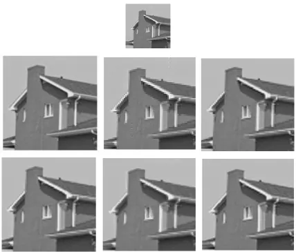
In this work still image of particular class of size M x M is selected as test image. A set of high resolution training images of same class is downloaded from internet each of size 2Mx2M to form a high resolution dataset, which is assessable. Such a set of downloaded high resolution images of same class is used as a training set. In this training set, 50 high resolution images are considered for the experimentation. In this experimentation four different discrete orthogonal and a biorthogonal wavelets are tested for their performance on particular class of test image. All the wavelets selected here are optimal in their resprctive family. The performance of different wavelet is evaluated on the basis of MSE and PSNR. The low resolution test image is obtained from its high resolution version through a low resolution image formation model which downsamples it by a factor of 2 [8]. This decimation model simulates the integration of light intensity that falls on the high resolution detector. Such obtained low resolution test image of size M x M is used for the experimentation. Figure 3(a) shows low resolution building image of size 64 x 64 pixels. Figure 3(b) shows the original high resolution image of size 128x128 which has prominent edges. Figure 3(c) shows same image upsampled by a factor of 2 using haar wavelet. Haar is a basic two point wavelet which is discontinuous, gives blurred edges and prominent artifacts at the edges in reconstructed image. Reconstructed image using Daubechies-4 is shown in figure 3(d). Daubechies wavelet, db4, which analysis is orthogonal, includes basic haar wavelet with the vanishing moments of number N and is not symmetrical. These wavelets have the ability to provide more number of vanishing moments for a given support width. The fourth order Daubechies wavelet has a vanishing moment of 4. It decomposes the polynomial of order 3 and wavelet function analyses the signal with trends of a third order polynomial. The reconstructed image shows little
/2, /2
/2, /2
]artifacts have been observed at the diagonal edges with blur. The reconstructed image shown in figure 3(f) is using Biorthogonal spline wavelet where exact reconstruction is possible with FIR filters. Here two wavelets have been used each for decomposition and reconstruction. Noticeable artifacts have been observed with more blurred image. Reconstructed image shown in figure 3(g) is using Discrete Meyer wavelet which is not compactly supported, gives compatible results with Biorthogonal spline wavelets with less blurred image.
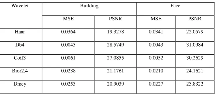
Figure 4(a) shows the low resolution image of face and figure 4(b) is its original high resolution version of size 128 x 128 with fine details. Figure 4(c) is reconstructed image using haar wavelets where mouth, noise and eyes are blurred and artifacts have been observed at curved edges. The details of eye and teeth have been lost. Reconstructed image shown in figure 4(d) is using db4 wavelets where more details of eye and teeth can be seen with less blur, but small artifacts are present at the face edges. Reconstructed image shown in figure 4(e) is using Coilflet wavelets where fewer artifacts with some details of face have been observed. Reconstructed image shown in figure 4(f) is using Biorthogonal spline wavelets which gives fewer details and added blur have been observed in the reconstructed image. Reconstructed image shown in figure 4(g) is using Discrete Meyer wavelet which is not having the compact support gives compatible results with Biorthogonal wavelets with less blur. Table 1 illustrates the results of different wavelets for both building and face class of images. The MSE and respective PSNR in terms of db are shown in the table. The learning of the low resolution test image depends on the training images in the dataset. All the wavelets used to evaluate the performance have almost same computational complexity in both classes. The mean squared error and PSNR is calculated as
b a b a
b
a
S
b
a
S
b
a
S
MSE
,
2 ,
2
,
,
ˆ
,
(2)
MSE
PSNR
10
log
255
^
2
(3)
WhereS
a
,
b
original high resolution image and
a
b
S
ˆ
,
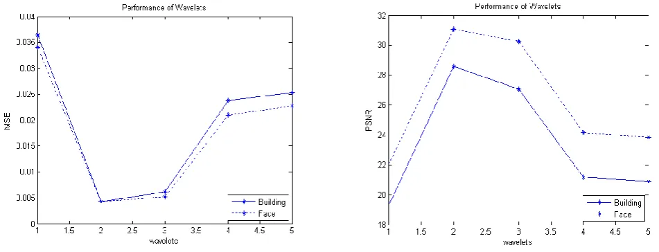
is reconstructed super resolved image. Figure 5(a) and 5(b) are the graphical illustration of MSE vs. Wavelets and PSNR vs. Wavelets used to assess the performance, in sequence as listed in table 1. Daubechies-4 bare minimum MSE and utmost PSNR for building and face class of images.4.
CONCLUSION
The experimentation shows Daubechies-4 wavelet gives superior performance with minimum blur and least amount of artifacts at the edges for both classes of images. Asymmetry of Daubechies has pronounced in both building and face class of images. The compatible results have been observed for Coilflet3 wavelet. The result improves as the vanishing movement increases within support. To avoid artifacts at the diagonal edges, directional filters can be used to improve the efficiency of the algorithm. The learning of the low resolution image depends upon how much training dataset is strong.
x
LL
n
x
L
n
Columns
x
LH
n
x
[
n
]
ROWS
x
HL
n
Columns
x
HH
n
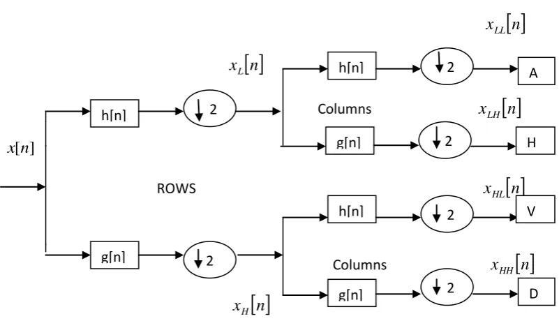
[image:3.595.314.540.85.289.2]
x
H
n
Fig 1: Illustration of wavelet subband decomposition
h[n]
g[n]
2
2
h[n]
g[n]
2
2
h[n]
g[n]
2
2
A
H
V
[image:3.595.61.462.457.687.2]Image 1
:
:
Test image
Image N [image:4.595.115.487.559.724.2]
Training Images
Fig 2: Illustrates the learning process
Table 1: Comparison of MSE and PSNR expressed in db
Wavelet Building Face
MSE PSNR MSE PSNR
Haar 0.0364 19.3278 0.0341 22.0579
Db4 0.0043 28.5749 0.0043 31.0984
Coif3 0.0061 27.0855 0.0052 30.2629
Bior2.4 0.0238 21.1761 0.0210 24.1621
Dmey 0.0253 20.9039 0.0227 23.8322
0
I IV
II III
V VI VII
VIII IX
0 I IV
II III VII
V VI
VIII IX
0 I IV
II III VII
V VI
VIII IX
Fig 3: a) Low resolution test Image b) Original High resolution image c) Super resolved using haar d) Super resolved using db4 e) Super resolved using coif3 f) Super resolved using bior2.4 g) Super resolved using dmey
[image:5.595.83.512.71.436.2]Fig 4: a) Low resolution test Image b) Original High resolution image c) Super resolved using haar d) Super resolved using db4 e) Super resolved using coif3 f) Super resolved using bior2.4 g) Super resolved using dmey
Fig 5: a) MSE vs. Wavelets b) PSNR vs. Wavelets
5.
REFERENCES
[1] S.Park, M.Park and Kang,” Super-Resolution image Reconstruction: A Tech. Overviwe,” IEEE Signal Processing Magazine. Vol.03,pp 21-36, May 2003. [2] M. Irani and S. Peleg,” Improving Resolution by Image
Registration,” CVGIP: Graphical Models and Image Processing, vol.53, pp. 231-239, March 1991..
[3] P. Vandewalle, L. Sbaiz, S. Süsstrunk and M. Vetterli, Registration of Aliased Images for Super-Resolution Imaging, Proc. SPIE/IS&T Visual Communications and Image Processing Conference, Vol. 6077, pp. 13-23, 2006.
[4] D.Rajan and S.Chaudhuri,” Generation of
Super-resolution Images from Blurred Observations Using an MRF Model,” J. Mathematical Imaging and Vision, vol. 16, pp. 5-15, 2002..
[5] D.Capel and A.Zisserman,”Super-resolution form
multiple views using learnt image model,” in Proc. of IEEE Computer Society Conf. on Computer Vision and
Pattern
Recognition(CVPR’01),vol.2,pp.II-627-[6] M.V.Joshi and S.Chaudhuri,” A learning based method for image super-resolution from zoomed observations,” Proc. of 5th Int. Conf. on Advances in Pattern Recognition (ICAPR’03) pp.179-182, Calcutta, India, Dec.2003.
[7] J. M. Shapiro, “Embedded image coding using zerotrees of wavelet coefficients,” IEEE Transactions on Signal Processing,vol. 41, no. 12, pp. 3445–3462, 1993 [8] C.V.Jiji, M.V.Joshi and S.Chaudhuri,” Single-frame
image super-resolution using learned wavelet
coefficients” International Journal of Imaging Systems and Technology, vol.14, no.3, pp.105-112, 2004
[9] Rao R M & Bopardikar A S, Wavelet Transform: Introduction to Theory and Application(Addison Wesley Longman Inc.)1998.
[image:6.595.86.512.75.213.2] [image:6.595.67.543.261.443.2]