4283
A RELIABLE IN-BAND CONTROL IN A
SOFTWARE-DEFINED NETWORK
ANATOLY S. KHAKHALIN*, EVGENY V. CHEMERITSKIY
Non-Profit Partnership "Applied Research Center for Computer Networks" (ARCCN), Moscow 142784, Russian Federation
* Address correspondence to this author at the Non-Profit Partnership "Applied Research Center for Computer Networks"(ARCCN), Moscowskiy town, Business Park «Rumyantsevo», Moscow 142784, Russian Federation E-mail:
[email protected] ABSTRACT
The development of wireless communication technologies has made it so the number of people who use them has surpassed the number of users of landlines. This causes malfunctions in and slow operation of networks. Software-defined networks separate data-forwarding processes from networking and communication processes – such networks allow for a significant reduction in the number of protocols used to improve the controllability of the network. This research investigates a method for establishing a reliable network connection, which will maintain the operability of the network in the presence of at least one route between switches, regardless of the number of failures. This study describes two methods of failsafe route generation – Non-return routes and Return routes. The paper provides a flowchart that shows the conditions that allow maintaining a connection to the switch. The proposed algorithm supports the OpenFlow protocol. In addition, the study established the rules that the controller sets for each separate switch. This method improves the fail-safety of the network and ensures its uninterrupted operation.
Keywords: Computer network, Forwarding plane, Network security, OpenFlow protocol 1. INTRODUCTION
This research studies Software-Defined Networks (SDN) [1–3] – a special class of computer networks, which is based on the idea of dividing the network into two planes: the forwarding plane, which is responsible for the forwarding of packets between hosts in the network, and the control plane, which uploads appropriate switching and routing settings to the network switching devices. A
controller is used to manage said settings; it is a program, whose commands control all the switches in the network. The compatibility of the controller with switches of various vendors and models is achieved through special control protocols that allow separating oneself from the internal switch. The most popular one is the OpenFlow protocol [4– 6].
OpenFlow is a basic protocol that is a key element of the SCD concept, which ensures the operation of the controller with network devices [23.24.25]. The controller is used to manage switch flow tables, which are used to make the decision to transfer the received packet to a specific switch port
[32.33.34]. Thus, direct network connections with minimum data transfer delays and required parameters are formed in the network.
The OpenFlow switch consists of at least two components:
• flow table [19.20]; • secure channel [21.22]
The advantage of SDN networks is their lower demand for technical experts, which ultimately reduces capital and operating costs [26.27.28]. In addition, SDN provides for quick service interaction, since data are programmed by remote control services (controllers) and applications. On a global scale, SDN transforms a network into a computational domain and integrates increasingly more standardization practices that are applicable to computers and software. In addition, researchers point out the following advantages of SDN networks [29.30.31]:
• Virtualization of the physical resources of the network
• Quick reaction to changes in the network • Simpler network adjustment
• Considerably less time required for application deployment
4284 • The SDN controller supports the open
application-programming interface (API), which enables programming it externally, creating an environment for automation and control, and scaling the functionality of future applications
• Visibility of the whole network traffic by the controller
Auxiliary equipment or dedicated communication lines are often used to maintain communication between the controller and switches [7–8]. Therefore, the network infrastructure of SDN is usually divided into two parts, each one maintaining the operation of its plane: the
forwarding plane network and the control plane network. If the control plane network is independent of the forwarding plane network, then the SDN controller performs an out-of-band control of the switches. Otherwise, the communication between the controller and the switches uses the same communication lines that are used to transfer user data – such control is called in-band control [9–10]. Since out-of-band control isolates service traffic from user traffic, it is more convenient and safe. However, out-of-band control requires auxiliary communication lines, which makes it very expensive and often impossible to implement in networks that connect objects located at great distances from each other. In such networks, the only possible option is integrated control, which has one significant drawback – the high complexity of maintaining a reliable connection to the controller. When using this type of control, failure of any communication line causes a disconnection between the controller and all switches connected via this line and may cause failures of entire segments of the network, which is unacceptable. Therefore, aside from a main set of packet forwarding rules, the controller should also preload into the switches some alterative rules to be used in case of each possible failure. The critical point of failure in the operation of the entire network is the SDN controller, which is why it is necessary to take its reliability and effectiveness into consideration during its operation. However, since high-quality controllers are expensive, it is necessary to develop a method that would enable improving the fail-safety of the network without replacing the current controller.
The size of the alternative route array required to maintain the connection between switches in case of several equipment failures
exponentially depends on their number [11–13]. In order to assure that a large network recovers after multiple failures, the controller may require to upload dozens and hundreds of additional packet forwarding rules to the switches. Since modern switches often support only several thousand rules, high fault-tolerance can cause a shortage of space for user traffic handling rules. Therefore, controller developers have to make a compromise between connection stability and overhead costs associated with its maintenance.
This research offers a new method to organize reliable communication between the switches and the controller. Using this method, the network is able to preserve control plane connectivity as long as the network topology maintains at least one route between them.
To that end, it is necessary to review some common methods of ensuring failsafe connections in SDN, to develop an approach to organizing a failsafe, and to give a detailed description of its implementation in terms of OpenFlow protocol.
2. RELATED WORK
The most common method to protect the connection between a switch and its controller is
static route backup [14, 15]. This method is based on a preliminary computation of several routes. The best one is used to connect the switch to the controller by default. If the forwarding plane detects a failure of this route, it automatically switches to the next best one. That way, the switch preserves its connection to the controller as long as the failures leave at least one of its static routes untouched.
4285
Figure 1. Example Of An Openflow Flow Table [18].
In practice, static route backup methods often do not cover all possible failure combinations. Therefore, they cannot guarantee the operability of all switches in the network after failures occur. If one were to generate a set of routes that would cover all the possible failure variants, then the number of rules that would have to be set on the switches would be unacceptably large. Consider two approaches to route generation, with a view to covering all possible failure variants.
Non-return routes. In order to maintain a failsafe status of an arbitrary communication line on the main route, it is necessary to map L static routes, where L is the number of communication lines on this route. Then the total number of routes and the number of rules on the switch are estimated as o(exp(L)), and o(N * exp(L)), respectively.
Return routes. If a failure is detected on the communication line on the main route, a return to the source node takes place and one of the alternative routes is used. Thus, up to (N – 1)! routes have to be computed for each switch, where N is the total number of switches in the network. Since a rule for each indicated route has to be set on each switch on this route, the number of rules on the switch can be calculated as o(exp(N)).
This research offers an original method for ensuring fail-safety, which allows maintaining the operation of the network in the presence of at least one route between switches. At that, the number of rules that have to be set on the switches is smaller than with static route backup.
3. OFFERED METHOD
Figure 2: Network Topology
[image:3.612.319.513.317.601.2]4286 switch connected to the controller via the shortest switch chain.
Assume all vertices of the network topology graph are enumerated based on the increase in the distance of these vertices to the controller vertex. In this case, when choosing the next vertex for sending the packet, one should choose the vertex with the smallest number amongst neighboring vertices. For instance, for switch 6, the route will be 6-3-1-0, where 0 is the controller.
If the communication line with such a vertex is broken, then the chosen packet transfer route cannot be used and the switch attempts to transfer the data via the neighboring vertex with the largest number. For instance, if the link 3-1 is broken, the route for switch 6 will be 6-3-4-2-0.
If all the lines apart from the one via which the packet has arrived are broken, then there is no routes that passes through this vertex is operable, and the switch shall return the packet. Consider Figure 1. If links 3-1 and 3-4 are broken, no route is available from switch 3 to the controller. In this case, the packet is returned to switch 6. On switch 6, vertex 3 will be excluded from the choice due to the lacking route from this vertex to the controller. Then, for switch 6, the route will be 6-4-2-0.
At some point, the packet may reach a vertex where it has already been. In order to rule out such cycles, it is necessary to know the vertices where the packet has already been. To that end, the term history is introduced – a sequence of numbers starting with the number of the source-switch and containing the initial part of the route via which the network attempted to deliver the packets from this switch to the controller.
In general, the controller should set such rules for each switch, so that the packets that its interfaces receive are processed according to the following algorithm:
Send the packet to the first active adjacent vertex with the smallest number;
When sending the packet, save the number of the current vertex to the history;
If a return on history occurs during the sending, the current vertex should not be entered into the history;
If the current vertex is in the history and is the last one, send the packet to the next
active adjacent vertex with a number that is higher than the number of the vertex the packet came from;
If the current vertex is in the history and is not the last one, send the packet to the last vertex in the history (in other words, to the port the packet came from).
The next section gives a detailed description of how the above algorithm can be coded using OpenFlow protocol rules.
4. OPENFLOW IMPLEMENTATION
In OpenFlow terms, the switch operation logic is set using a packet handling rule table [17]. Each rule contains a set of simple actions, for instance, transcription of the packet header and transfer of the packet via indicated port, and a
pattern – a rule is applied to a packet only if the packet fits the pattern for the rule [19]. Each bit of the pattern can have one of three values: 0, 1, and
substitute (*). The packet header fits the pattern only if each bit of the header is exactly equal to the corresponding bit of the pattern or (*) is used in this bit of the pattern.
We assume the switches in the modeled network should support the OpenFlow protocol version 1.1 or higher, support fast-failover groups, and have at least three rule tables. Each packet has a header that consists of several fields. Each field is a set of bits. The MAC address field will be used to handle the history. To that end, the field is divided into sections of equal length; a binary representation of the switch number will be written down in each section. It is expedient to introduce the following designations:
r is the number of bits dedicated to the switch number;
l is the maximum number of switches in the history (history length);
k is the number of bits in the field dedicated to storing history.
It is worth noting that the switch number should be unique, in which case, the number of bits dedicated to the switch number is r=log2N, where N is the number of switches in the network.
4287
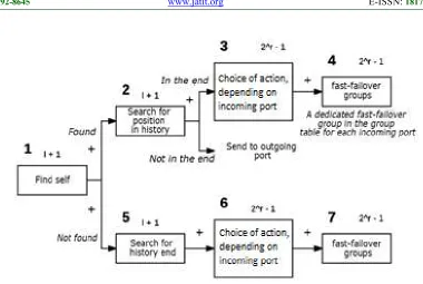
Figure 3:Openflow Tables And Groups For Packet Handling
1. In the first table, the presence of the current switch in the history is determined. The pattern for each rule in this table is a sequence with r length for comparison to the MAC field of the packet. With that, each sequence is a binary representation of the switch number and is located with r*i shift, where i is the sequence number of the rule starting with 0. In other words, all possible locations of the switch number in the history are checked. All the bits that are not part of the current verification section take on substitute values. If the switch is found in the history, proceed to table 2; otherwise, proceed to table 7. The number of rules in this table is l + 1.
2. Determine the position of the switch in the history. If the switch number is encountered in the middle of the history – a loop is created, which requires a return on history, in which the packet is sent to the port via which it was received. The determination of the switch position in the history requires the introduction of rules, the pattern whereof is divided into three parts: comparison-to-number section, pre-section bits, and post-section bits. Pre-section bits have substitute values; post-section bits
have zero values. Thus, if a match is found for one of such patterns, then the switch is located at the end of the history; otherwise, a loop is created. In case of return on history, the packet is sent to the outgoing port. If the switch number is located at the end of the history, proceed to Table 3. The number of rules in this table is l + 1. 3. It is necessary to determine the following
table based on the port via which the packet was received. This will determine the routes that should be checked, since it is necessary to check only the neighboring switches, the number whereof is higher than the number of the switch from which the packet came. This is due to the fact that the packet is forwarded to the minimum number and if the packet has returned from any switch, then it has already been to the switches with a number that is lower than the one it returned from. The number of rules in this table is 2r–1.
4288 ports, starting with the number that is higher than the number of the switch the packet came from. At this stage, 2r– 1 entries in
the group table are introduced.
5. Determine the end of the history to record own number. To that end, the pattern of rules in the table under consideration checks the position of the last zero section. The verifications takes place by sections of r bits; preceding bits have the (*) value; following bits have zero value. The number of rules in this table is l + 1.
6. Similar to 3.
7. Depending on the port via which the packet was received, it is sent to one of the fast-failover entries in the group table, where the packet is forwarded to the first operating port on the list arranged in ascending order of numbers of switches connected via said ports, with the exception of the incoming port. At this stage, 2r–1 entries in the group
table are introduced.
In other words, two situations can occur during the operation of the algorithm – fast-failover forwarding according to certain rules and return on history in case a loop is created or all fast-failover forwarding options at the current vertex are exhausted.
Consider an estimation of the number of rules during the operation of the algorithm offered in this research.
The number of rules M that has to be set on one switch is as follows:
M = 3l + 3 + 4*(2r - 1) (1)
Considering that r = log2N and =
where k ≤ N,
( ) = (2 − 1) = ( ) (2)
Thus, in order to maintain a connection to one switch, it is necessary to set a number of rules on other switches that is linearly dependent on the number of switches. This operation should be performed for each switch. As a result, the offered method requires setting o(N) rules, while static backup requires o(exp(N)) rules.
5. CONCLUSION
This research developed and investigated a method of organizing a reliable in-band control
in SDN. When it is necessary to achieve fail-safety, with which the network continues to operate in the presence of at least one functional route, the developed method uses significantly fewer rules than static route backup does. The study found two ways of generating routes that would cover all possible failures – Non-return routes and Return routes.
In addition, the research developed a schematic instruction that describes the conditions that maintain the connection to the switch. As a result, the operation of the network is not interrupted and no time is required for file backup in case of a network failure. The developed idea consists in the fact that all communication lines with integrated control are operational and in order to deliver packets from an arbitrary switch to the controller it is sufficient to deliver it to any switch that is connected to the controller along the shortest switch chain. In addition, the research provided a list of rules that the controller should set for each switch.
The offered algorithm supports the OpenFlow protocol that controls the switch using OpenFlow tables and groups for packet handling, where each bit of the pattern can have one of three values.
Thus, the offered method reduces the frequency of network failures, which allows optimizing its operation and improving its functionality.
CONFLICTOFINTEREST
The authors confirm that this article content has no conflict of interest.
ACKNOWLEDGEMENTS
This research is supported by the Ministry of Education and Science of the Russian Federation, Unique ID RFMEFI60914X0003
REFERENCES:
4289 [2] C. S. Li and W. Liao, “Software defined
networks.,” IEEE Commun. Mag., vol. 51, no. 2, pp. 113–114, 2013.
[3] N. Feamster, “Software defined networking.,” 2013.
[4] “Open Networking Foundation, ‘OpenFlow Switch Specification’, March 26, 2015. Available:
https://www.opennetworking.org/images/st ories/downloads/sdn-resources/onf- specifications/openflow/openflow-switch-v1.3.5.pdf. [Retrieved on: May 14, 2016].” . [5] K. Kirkpatrick, “Software-defined networking,” Commun. ACM, vol. 56, no. 9, p. 16, Sep. 2013.
[6] C. Monsanto, J. Reich, N. Foster, J. Rexford, D. Walker, and P. Cornell, “Composing Software-Defined Networks,” pp. 1–13, 2013.
[8] S. Sezer, S. Scott-Hayward, P. Chouhan, B. Fraser, D. Lake, J. Finnegan, N. Viljoen, M. Miller, and N. Rao, “Are we ready for SDN? Implementation challenges for software-defined networks,” IEEE Commun. Mag., vol. 51, no. 7, pp. 36–43, Jul. 2013.
[9] D. Kreutz, F. M. V. Razmos, and P. Verissimo, “Towards secure and dependable software-defined networks,” in Proceedings of the second ACM SIGCOMM workshop on Hot topics in software defined networking - HotSDN ’13, 2013, p. 55.
[10] S. Shin, P. Porras, V. Yegneswaran, M. Fong, G. Gu, and M. Tyson, “FRESCO: Modular Composable Security Services for Software-Defined Networks,” 2013.
[11] M. Yang, Y. Li, D. Jin, L. Zeng, X. Wu, and A. V. Vasilakos, “Software-Defined and Virtualized Future Mobile and Wireless Networks: A Survey,” Mob. Networks Appl., vol. 20, no. 1, pp. 4–18, Feb. 2015.
[12] W. Han, H. Hu, Z. Zhao, A. Doupé, G.-J. Ahn, K.-C. Wang, and J. Deng, “State-aware Network Access Management for Software-Defined Networks,” in Proceedings of the 21st ACM on Symposium on Access Control Models and Technologies - SACMAT ’16, 2016, pp. 1–11.
[13] S. Scott-Hayward, S. Natarajan, and S. Sezer, “A Survey of Security in Software Defined Networks,” IEEE Commun. Surv. Tutorials, vol. 18, no. 1, pp. 623–654, 2016. [14] S. Sharma, D. Staessens, D. Colle, M. Pickavet, and P. Demeester, “In-band control, queuing, and failure recovery functionalities for openflow,” IEEE Netw.,
vol. 30, no. 1, pp. 106–112, Jan. 2016. [15] S. Sharma, “Fast failure recovery for in-band
OpenFlow networks,” IEEE Xplore Digit. Libr., 2013.
[16] “Openvswitch.org, ‘Design Decisions In Open vSwitch’, March 30, 2016. Available:
http://openvswitch.org/support/dist-docs/DESIGN.md.txt. [Retrieved on: April 18, 2016].” .
[17] “OpenFlow, ‘Network Planning’, 2011. Available:
http://archive.openflow.org/wp/deploy-production-planning/. [Retrieved on: 2016].” .
[18] SDN technologies – Software Defined Networking. Electronic resource [https://habrahabr.ru/company/muk/blog/25 1959/]
[19] Lee S. S. W. et al. Path layout planning and software based fast failure detection in survivable OpenFlow networks. Design of Reliable Communication Networks (DRCN), 2014 10th International Conference on the. IEEE, 2014. pp. 1-8. [20] Cvijetic N. et al. SDN and OpenFlow for
dynamic flex-grid optical access and aggregation networks. Journal of Lightwave Technology. 2014. Vol. 32. No. 4. pp. 864-870.
[21] Capone A. et al. Detour planning for fast and reliable failure recovery in SDN with OpenState. Design of Reliable Communication Networks (DRCN), 2015 11th International Conference on the. IEEE, 2015. pp. 25-32.
[22] Kobayashi M. et al. Maturing of OpenFlow and software-defined networking through deployments. Computer Networks. 2014. Vol. 61. pp. 151-175.
[23] Ji P. N. et al. Demonstration of OpenFlow-enabled traffic and network adaptive transport SDN Optical Fiber Communication Conference. Optical Society of America, 2014. pp. W2A. 20. [24] Akyildiz I. F. et al. A roadmap for traffic
engineering in SDN-OpenFlow networks. Computer Networks. 2014. Vol. 71. pp. 1-30. [25] Giotis K. et al. Combining OpenFlow and sFlow for an effective and scalable anomaly detection and mitigation mechanism on SDN environments. Computer Networks. 2014. Vol. 62. pp. 122-136.
4290 2014. pp. 1734-1742.
[27] Hu F. (ed.). Network Innovation through OpenFlow and SDN: Principles and Design. CRC Press, 2014.
[28] Smeliansky R. L. SDN for network security. Science and Technology Conference (Modern Networking Technologies) (MoNeTeC), 2014 First International. IEEE, 2014. pp. 1-5.
[29] Chou W., Luo M., Lin K. System and apparatus of generalized network controller for a software defined network (SDN): USA patent 8982727. 2015.
[30] Adami D. et al. Towards an SDN network control application for differentiated traffic routing. Communications (ICC), 2015 IEEE International Conference on. IEEE, 2015. pp. 5827-5832.
[31] Blenk A. et al. Pairing SDN with network virtualization: The network hypervisor placement problem. Network Function Virtualization and Software Defined Network (NFV-SDN), 2015 IEEE Conference on. IEEE, 2015. pp. 198-204. [32] Röpke C., Holz T. Retaining control over
SDN network services. Networked Systems (NetSys), 2015 International Conference and Workshops on. IEEE, 2015. pp. 1-5. [33] Cabaj K. et al. SDN Architecture Impact on
Network Security. FedCSIS Position Papers. 2014. pp. 143-148.
![Figure 1. Example Of An Openflow Flow Table [18].](https://thumb-us.123doks.com/thumbv2/123dok_us/8906245.956969/3.612.319.513.317.601/figure-example-of-an-openflow-flow-table.webp)