ABSTRACT
RAGHAVAN, SUDARSHAN NARASIMHA. The Terminal Node Controlled Routing Protocol for Mobile Ad Hoc Networks. (Under the direction of Professor Arne A. Nilsson.)
Dedicated to my parents
BIOGRAPHY
ACKNOWLEDGEMENTS
Contents
List of Figures ix
List of Tables xi
1 Introduction 1
1.1 Background ……….. 1
1.2 Motivation ……… 2
1.3 Organization of the Thesis ………... 3
2 Ad Hoc Wireless Networks 4
2.1 Characteristics of Ad Hoc Networks .……….. 5
2.2 Problems and Challenges in Ad Hoc Networks ………... 7
2.2.1 Regulations and Incompatible Standards ……….. 7
2.2.2 Problems at the Physical Layer ……… 7
2.2.3 Medium Access ……… 8
2.2.4 Routing ………..………... 8
2.2.5 Resource Limitations ………..……….. 9
2.2.6 Transport Layer ……… 9
2.2.7 Localization ……….. 9
2.2.8 Other Challenges ………... 10
3 Routing in Mobile Ad Hoc Networks 11
3.1 An Overview of Proposed Routing Protocols for MANET ………... 12
3.1.1 Destination Sequenced Distance Vector Routing (DSDV) ……… 13
3.1.2 Optimal Link State Routing (OLSR) ………..……… 14
3.1.3 Fisheye State Routing (FSR) ………... 15
3.1.4 Dynamic Source Routing (DSR) ………... 16
3.1.6 Temporally Ordered Routing Algorithm (TORA) ……….. 19
3.1.7 Associativity Based routing (ABR) ………... 20
3.1.8 Zone Routing Protocol (ZRP) ………..…….. 22
3.2 Performance of Ad hoc Routing Protocols ………...………. 23
3.2.1 Performance of DSDV ……….…….. 24
3.2.2 Performance of OLSR ……… 24
3.2.3 Performance of FSR ………...…… 25
3.2.4 Performance of DSR ………...………… 25
3.2.5 Performance of AODV ………...……… 26
3.2.6 Performance of TORA ………...……… 26
3.2.7 Performance of ABR ……….. 27
3.2.8 Performance of ZRP ……….……….. 28
4 Unidirectional Links in Mobile Ad Hoc Networks 29
4.1 Occurrence of Unidirectional Links in Ad Hoc Networks …………...………. 29
4.1.1 Disparity in Transmit Power and Receiver Sensitivity ……….………. 31
4.1.2 Disparity in Antenna Characteristics ……….………. 33
4.1.3 Disparity in Noise Levels at the Receiver Node ……… 34
4.2 Impact of Unidirectional Links ………..……… 35
4.2.1 Impact of Unidirectional Links on Link Layer Protocols ……….. 36
4.2.2 Impact of Unidirectional Links on Routing Protocols …………..……. 38
4.3 DSR and Unidirectional Links: A Case Study ………..………. 40
4.3.1 Route Request Storms ………..………….. 40
4.3.2 Route Maintenance and Chain Reactions ………..………. 42
4.3.3 Caching ………..…………. 43
4.4 Related Work ………. 45
5 The Terminal Node Controlled Routing Protocol 46
5.1 Introduction ……… 46
5.3 Terminology ……….……….. 48
5.4 Packet Types ……….………. 49
5.5 Destination Information Structure ………. 51
5.6 Important Parameters ………...……….. 52
5.7 TNCR – Important Features ………...……… 53
5.7.1 Controlled Flooding ………..………….. 53
5.7.2 Broadcast Limiting ………...……….. 54
5.7.3 Reverse Caching ……….……… 55
5.7.4 End-to-End Probing ………...………. 56
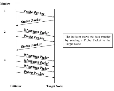
5.7.5 Slow Start Data Transmission ………...………. 57
5.7.6 Route Stripping ……….……….. 59
5.7.7 Active Caching and Cache Tagging ………..……. 60
5.8 TNCR Protocol Description ……….………….. 62
5.8.1 Route Establishment ………...……… 62
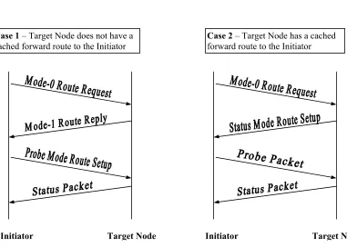
5.8.1.1 State_1 Route Establishment ………...………. 63
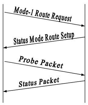
5.8.1.2 State_2 Route Establishment ………..…….. 63
5.8.1.3 Points to Note ………...……… 65
5.8.2 Data Transfer ……….. 66
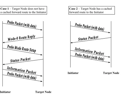
5.8.2.1 State_3 Data Transfer ………..………. 66
5.8.2.2 State_4 Data Transfer ………..…………. 66
5.8.2.3 Points to Note ………...……… 67
5.8.3 Route Failure Detection ……….. 68
5.8.3.1 Failure Detection and Recovery at the Initiator ………...…… 69
5.8.3.2 Failure Detection and Recovery at the Target Node ……... 69
5.8.3.3 Significance of FT1 and FT2 Parameters …………..….…….. 70
5.8.4 Propagation of Failure Information ………..……….. 71
5.8.5 Late Arrivals and Response Filtering ………...……….. 72
5.8.6 Bi-directional Mode ………..…….. 74
5.8.6.1 Bi-directional Route Establishment …………...…….……….. 75
6 Simulation Environment 77
6.1 TNCR Node Model ……… 77
6.2 TNCR Power Models ………. 80
6.2.1 Two Power Model ………..……… 80
6.2.2 Random Power Model ……… 81
6.3 TNCR Process Model ………..……….. 82
6.3.1 Route Cache and Packet Buffer ……….……… 83
6.3.2 Support Packages ………..……….. 84
6.3.3 Inter-Process Communication and Packet Formats ……… 85
6.3.4 Hop Delay and Timeout ………. 86
6.3.4.1 Delay Calculation for Request Packets ………... 86
6.3.4.2 Delay Calculation for Reply Packet ………...…….. 86
6.3.4.3 Delay Calculation for Data Packets Sent in Succession …... 87
6.4 Mobility Model ………..…………...……. 88
6.4.1 FSM States ……….. 89
7 Results and Conclusions 91
7.1 Unidirectional Mode Simulations ………..……… 91
7.1.1 Packet Delivery Ratio ………. 94
7.1.2 End-to-End Delay ………..…………. 95
7.1.3 Routing Load ……….………. 96
7.2 Bi-directional Mode Simulations ……….……… 100
7.3 Conclusions ……….. 103
8 Future Work 106
Appendix A 108
Appendix B 112
List of Figures
2.1 A Typical Mobile Ad Hoc Network ………...………….. 6
3.1 Route Discovery in DSR ……….………...………… 17
3.2 Route Creation in TORA ……….………...………… 19
3.3 Route Maintenance in TORA …………..………...………… 20
4.1 Unidirectional Link Due to Disparity in Transmission Range ………...………… 32
4.2 Unidirectional Link Due to Disparity in Antenna Characteristics ……….……… 34
4.3 Ad Hoc Network with Unidirectional Links ………...……...………… 36
4.4 Hidden Terminal Problem ………...…...………… 36
4.5 RTS-CTS Exchange Mechanism ………...………… 37
4.6 DSR Route Discovery in Ad Hoc Networks with Unidirectional Links ………… 41
4.7 DSR Route Maintenance in the Presence of Unidirectional Links …....………… 42
4.8 DSR Caching in the Presence of Unidirectional Links …………...…...………… 43
5.1 Broadcast Limiting ………..……...………… 55
5.2 Reverse Caching ………..……...………… 56
5.3 Slow Start Data Transmission ………..……...…...…… 58
5.4 Route Stripping ………..…...………..……...………… 60
5.5 Active Caching and Cache Tagging ………....……...………… 61
5.6 State_1 Route Establishment ……….………..……...………… 64
5.7 State_2 Route Establishment ……….………..……...………… 65
5.8 State_3 Data Transfer ………...………….………..……...………… 67
5.9 State_4 Data Transfer ………...………….………..……...………… 68
5.10 Significance of FT1 and FT2 ……...…….………..……...………… 70
5.11 Propagation of Failure Information ………...………….……….……...………… 72
5.13 Bi-Directional Route Establishment ………...………….………...………… 75
5.14 Bi-Directional Data Transfer ………...…………....………...………… 76
6.1 OPNET TNCR Node Model ………...……...………….………...………… 78
6.2 TNCR Process Model ………..……...………….………...………… 82
6.3 Destination Information Structure ……...…...………….………...………… 84
6.4 TNCR Packet Formats ……….……...……...………….………...………… 85
6.5 Hidden Terminal Collision Avoidance ………...…...….………...………… 87
6.6 Random Waypoint Process Model ……..…...………….………...………… 88
7.1 Packet Delivery Ratio – Unidirectional Mode ………..………. 94
7.2 Avg. End-to-End Delay – Unidirectional Mode ………..…….. 96
7.3 Normalized Routing Load – Unidirectional Mode ……… 97
7.4 Routing Load Analysis – TNCR ………...………. 98
7.5 Routing Load Analysis – DSR ………...……… 99
7.6 Effective Routing Load – DSR vs. TNCR ………... 99
7.7 Packet Delivery Ratio – Bi-directional Mode ……….………..……... 101
7.8 Avg. End-to-End Delay – Bi-directional Mode …….………..…… 102
7.9 Normalized Routing Load – Bi-directional Mode ……….……….. 102
List of Tables
3.1 Categorization of Ad Hoc routing Protocols ………...………...………… 13
3.2 Other Protocols for Routing in MANET …….………...………… 23
3.3 Performance of Ad Hoc routing Protocols - References ……….………… 23
5.1 Query Packets and Expected Responses ……….………...………… 74
7.1 TNCR Specific Parameters – Unidirectional Mode ……….………….. 93
Chapter 1
Introduction
1.1 Background
A wireless mobile ad hoc network (MANET) is an autonomous collection of mobile nodes that do not rely on pre-existing infrastructure for communication. The network is decentralized and the nodes in the network can be interconnected in an arbitrary manner. Ad hoc networks have no fixed routers and all the nodes in the network perform the routing functionality. Due to nodal mobility, the network topology may change rapidly and unpredictably over time. Routing in a decentralized, wireless environment with fluctuating topologies is not a well-defined problem and over the past few years, several protocols have been proposed for routing in mobile ad hoc networks.
RTS-CTS exchange mechanism to overcome the hidden terminal problem and depends on link level acknowledgments for proper delivery of unicast packets. However, in the presence of unidirectional links, it not possible to use a link level handshake mechanism. Most existing ad hoc routing protocols rely on path reversal techniques and link level acknowledgements for route establishment, path failure discovery and route maintenance. These protocols either fail to work or become highly inefficient in the presence of unidirectional links. Solutions that have been proposed for handling unidirectional links are modifications to existing ad hoc routing protocols. They typically use a broadcast mechanism for neighbor sensing and detection of unidirectional links in the network. Most solutions avoid the formation of routes with unidirectional links and involve high overheads for detecting unidirectional links and maintaining bi-directional paths. In addition, they do not take into account the improved network connectivity and better routes that can result from utilizing unidirectional links in the network.
1.2 Motivation
involves evaluation of the proposed protocol through detailed simulation on a variety of network topologies and communication patterns.
1.3 Organization of the Thesis
Chapter 2
Ad Hoc Wireless Networks
With the advancement in technology, reduction in costs and the constant demand for flexibility and ease of use, wireless networks have seen tremendous growth over the past decade. Wireless networks can be classified in two types: Infrastructured Networks and Ad Hoc Networks. An infrastructured network consists of fixed gateways called base stations and several mobile nodes operating within the communication radius of these base stations. When a mobile node moves out of range of one base station into the range of another base station, a handoff occurs and the mobile node starts communicating through the new base station. Communication is not possible in areas that do not have the fixed infrastructure. Currently, infrastructured networks are used in cellular communication and wireless LANs.
Ad hoc networks are infrastructureless networks in which nodes are mobile and can be connected dynamically in an arbitrary manner. Each node acts not only as a host, but also as a router and takes part in route discovery and maintenance of routes to other nodes in the network. A node that wants to communicate with another node outside its communication radius does so by forwarding the data over several hops, thus forming a decentralized, multi-hop wireless network. Since these networks can be rapidly deployed without any pre-existing infrastructure, ad hoc networks have also been referred to as “instant infrastructure” networks.
Area Networks (PAN) to form a localized network of devices that are closely associated with a single person [42]. Inter-PAN and Intra-PAN communication in the presence of user mobility could benefit from the technologies of ad hoc networking. Yet another application is in the area of “Ubiquitous Computing”, in which the environment is envisioned to be a virtual network of intelligent devices that can communicate with each other and respond to changing environmental conditions. The ad hoc concept can be extended to form wireless sensor networks [57] in which the node positions are fixed once they are deployed. Search and rescue operations, weather monitoring, vehicle tracking and military reconnaissance are few examples of applications of sensor networks.
2.1 Characteristics of Ad Hoc Networks
The origins of ad hoc networking can be traced to the 1970s when DARPA initiated the Packet Radio Network (PRNET) project [42]. However, the concept of commercial ad hoc networks came into the picture in the early 1990s when the IEEE 802.11 subcommittee adopted the term “Ad Hoc Networks”. Mobile ad hoc networks have several salient characteristics [9]:
1. A mobile ad hoc network (MANET) is an autonomous system of mobile nodes, each equipped with wireless communications and networking capability. It is a collection of communication devices that have no fixed infrastructure and have no predetermined organization of available links. Ad hoc networks can be built around any wireless technology including infrared and radio frequency (RF).
3. The nodes in an ad hoc network can been heterogeneous. Thus parameters like transmission power level, antenna characteristics and co-channel interference greatly affect communication performance and design of communication protocols.
4. The wireless links are bandwidth constrained and may have variable capacity. The network can consist of both unidirectional and bi-directional links
5. The nodes are typically battery operated and employ power control mechanisms to limit battery consumption. These power control algorithms have a direct bearing on the network topology since the node transmission range and the ability of a node to forward packets for other nodes depends on the available power.
Figure 2.1 illustrates a typical wireless mobile ad hoc network composed of seven nodes along with the links between them. Note that links in an ad hoc network can be unidirectional.
Figure 2.1: A Typical Mobile Ad Hoc Network
The nodes are mobile and can move relative to each other in a random arbitrary manner. As the nodes move, links are broken and new links are established. Existing nodes can leave the network and new nodes may join the network Thus the network topology can change rapidly and unpredictably over time. In the figure, node A moves away from nodes B, C, D and
F leaves the network A
B
C
D
E
G
F A A moves towards E
H B
D
E
G C
A
establishes a new bi-directional link with node E. Node F leaves the network and node H joins the network leading to an arbitrary change in the network topology over time.
2.2 Problems and Challenges in Ad Hoc Networks
Ad hoc networking is a multi-layered problem. Over the past few years, the field has generated lot of interest in the research community and has seen a rapid expansion in visibility and work. This section discusses the problems and challenges facing the ad hoc model of networking.
2.2.1 Regulations and Incompatible Standards
The radio spectrum for wireless communication is limited and allocation of frequencies is regulated by several national and international agencies. Since ad hoc networks are formed and destroyed on the fly, they are expected to operate over the license-free ISM band. Many household devices like microwave ovens operate in this band (2.4 GHz ISM). Thus, interference is a primary concern in this band. Also, the transmit power of mobile devices operating in this band is usually regulated to prevent excessive interference with other devices. Yet another problem is the plethora of routing protocols, wireless channel access and coding techniques available for mobile communication. A large design space can lead to the development of incompatible solutions, each trying to solve a different part of the problem [42]. Incompatible solutions will lead to interoperability issues in ad hoc networks. Standardization of protocols and techniques for ad hoc networks will become a challenge once the field gains wide acceptance.
2.2.2 Problems at the Physical Layer
efficiently utilize the available bandwidth [50]. Another area that has generated much interest in the research community is the design of steerable smart antennas for wireless devices that can adapt to changes in the signal environment and thus, optimize the radiation/reception pattern.
2.2.3 Medium Access
Nodes in an ad hoc network have to contend for the medium similar to the nodes in a cellular network. However, unlike cellular networks, ad hoc networks are decentralized and lack global synchronization [57]. Thus there is no central entity to control access to the medium. Many MAC protocols that have been proposed for infrastructured wireless networks do not account for host mobility and fluctuating network topologies and are unsuitable for ad hoc networks. Node mobility and presence of unidirectional links aggravate the hidden terminal and exposed terminal problems in ad hoc networks. Due to the possibility of unidirectional links in an ad hoc network, it might not be possible to use MAC protocols that work on a bi-directional framework and rely on link level acknowledgements for forwarding packets to a neighboring node.
2.2.4 Routing
2.2.5 Resource Limitations
Mobile devices have limited computing power and are memory constrained. However an even bigger problem is power consumption. Nodes in an ad hoc network are typically powered by batteries and thus, power conservation becomes an important issue. In an ad hoc network, nodes have to forward packets on behalf of other nodes and this consumes power. The ability of a node to forward packets thus becomes a function of the available power at the node. Power also affects the topology in an ad hoc network. Two nodes with differing power levels can have different transmission ranges thus leading to the formation of unidirectional links in the network.
2.2.6 Transport Layer
Transport layer protocols like TCP were designed for wired networks with static nodes and only perform flow control and congestion control activities at the source and the destination nodes [57]. TCP relies on round trip time (RTT) estimates to detect and avoid network congestion. However, in an ad hoc network with dynamic topologies, delays are highly unpredictable. Mobility can make and break links randomly and thus lead to packet loss. However this can be interpreted as network congestion by protocols like TCP resulting in low communication throughput. Several enhancements are required to make existing transport layer protocols suitable for ad hoc networks.
2.2.7 Localization
consume a lot of power and do not work indoors. Design of GPS-less localization algorithms for ad hoc networks is a topic that has generated lot of interest in the ad hoc research community.
2.2.8 Other Challenges
Chapter 3
Routing in Mobile Ad Hoc Networks
Routing protocols for the wired Internet can be classified into two categories, Link State Protocols and Distance Vector Protocols. Link state protocols like OSPF [32] are based on network broadcasts for exchanging information about the state of the links that have been established between the nodes in the network. Once the link state information has been aggregated, the Shortest Path First algorithm (Dijkstra’s Algorithm) [11] is used to determine the optimal route from the source to the destination. Link state algorithms for the Internet cannot be used in ad hoc networks because nodal mobility can cause rapid changes in the network topology. The number of control messages required to maintain connectivity information for routing starts increasing as a function of nodal mobility. The increased number of control messages can consume a substantial percentage of the available bandwidth, and in highly dynamic networks, convergence1 becomes almost impossible.
Distance vector protocols, like Routing Information Protocol (RIP) [29], typically use the Distributed Bellman Ford algorithm [4]. In traditional distance vector protocols, every node maintains for each destination, a single routing table entry containing the number of hops to the destination and the next hop toward the destination. Distance vector algorithms are more efficient than link state protocols in terms of memory and computational requirements. However, these algorithms suffer from very slow convergence (count to infinity problem) due to exchange of stale information and can lead to the formation of long-lived loops. These problems become worse in an ad hoc network due to unpredictable changes in the network topology.
Routing in ad hoc networks is a topic that has seen a tremendous expansion in visibility and work over the past few years. Spurred by the growing interest in the field, the Mobile Ad Hoc Networks (MANET) working group [9] was formed within the IETF to standardize routing protocols for ad hoc networks. The inability of existing routing protocols to deal with the limitations of ad hoc networks, which include rapidly changing topologies due to nodal mobility, low bandwidth, power constraints and high error rates has triggered the need for new routing protocols for ad hoc networks. The goal is to provide a peer-to-peer routing capability that reacts efficiently to topological changes while maintaining effective communication in a mobile networking context. Routing in ad hoc networks can be viewed as the ultimate challenge for network protocol designers and it may turn out that protocols designed for ad hoc networks can be adapted to improve the scalability of existing Internet routing protocols.
3.1
An Overview of Proposed Routing Protocols for MANET
Routing protocols for mobile ad hoc networks can be categorized into two types: proactive protocols and on-demand protocols [49]. Proactive protocols are table driven protocols in which each node tries to maintain consistent routing information to every other node in the network. This is achieved by propagating routing updates to reflect changes in the network topology caused due to mobility and node failures. Some updates are localized and are used for neighbor sensing while some updates are propagated throughout the network. Proactive protocols immediately provide the required routes when needed, at the cost of bandwidth used for propagating periodic control messages.
While most protocols fall into one of these categories, some protocols use a hybrid approach by limiting the scope of the proactive procedure to the node’s local neighborhood. The route discovery is done on an on-demand basis similar to reactive protocols. However, these protocols try to minimize the search cost involved with route discovery by querying only selected nodes in the network. The following sections describe few routing protocols that have been proposed for ad hoc networks. Table 3.1 lists the protocols that have been considered and categorizes them as proactive or reactive protocols.
Proactive Protocols Reactive Protocols Hybrid Protocol
DSDV DSR ZRP OLSR AODV FSR TORA
ABR
Table 3.1: Categorization of Ad Hoc Routing Protocols [49]
3.1.1
Destination Sequenced Distance Vector Routing (DSDV)
However, in highly dynamic networks, incremental updates can grow big and full dumps will be more frequent.
Each route broadcast contains the address of the destination, the number of hops to reach the destination, the sequence number of the information received regarding the destination and a new sequence number unique to the broadcast. The broadcast sequence number helps a node to discard duplicate packets. The route labeled with the most recent sequence number is always used. If two updates have the same sequence number, the one with the best metric is used. Based on the past history, each node estimates the average time that a route to a destination will fluctuate (settling time) before the route with the best metric is received. The transmission of routing updates is delayed by the settling time to eliminate routing updates that would occur if a better route were found in the near future.
3.1.2 Optimal Link State Routing (OLSR)
Each node periodically broadcasts a Topology Control (TC) message to declare its MPR selector list. The MPRs are used to minimize the flooding of broadcast packets in the network. When a node broadcasts a packet, only the multipoint relays of the node retransmit the packet. Neighbors that are not in the MPR set, read and process the packet but do not retransmit it. Nodes with empty MPR selector lists do not generate TC messages. TC messages are both time driven and event driven. When a change occurs in the MPR selector list, the TC message may be sent earlier than the scheduled time. These TC messages permit a node to learn about possible destinations (the MPR selectors listed in the TC message) and the last hop node to the destination (the originator of the TC message). To find a path from a node to a destination D, the node has to find a connected pair (X,D) and then a connected pair (Y,X) and so forth till it finds a node in its one hop neighborhood. This neighbor is the next hop node to the destination D. Based on this information, each node constructs a routing table that records all possible destinations, the next hop address and the estimated distance to the destination. Sequence numbers are used to distinguish stale updates from new ones.
3.1.3 Fisheye State Routing (FSR)
records all possible destinations, the link state information reported by each node in the destination list, the next hop on the shortest path from the node to the destination and the estimated distance to the destination. Similar to pure link state protocols, the Dijkstra’s algorithm [11] is used to compute the shortest path route to a destination.
3.1.4 Dynamic Source Routing (DSR)
Figure 3.1: Route Discovery in DSR
Route maintenance in DSR is achieved through the use of per-hop acknowledgements and route error packets. When the source node sends a packet to the destination using a source route, each node along the route is responsible for confirming that the packet has been received by the next hop. This confirmation may be obtained in the form of link-level acknowledgements or through passive acknowledgements (where a node is able to overhear the next hop forwarding the packet along the route). If neither of these mechanisms is available, a node may request a network level acknowledgment from the next hop. When a node detects a link failure, it sends a route error packet to the original sender. When a route error packet is received, all routes containing the hop in error are deleted from the node’s cache. A fresh route request is generated, if required. Nodes continually learn new routes when they forward packets or overhear other transmissions and update their route cache. Several optimizations like expanding ring search, packet salvaging and automatic route shortening have been proposed for DSR. The reader is referred to [23] for more details regarding these optimizations.
3.1.5 Ad Hoc On-Demand Distance Vector Routing (AODV)
AODV [41] is an adaptation of the DSDV algorithm [40] previously described. It improves DSDV by using an on-demand route discovery mechanism to minimize the number of required broadcasts. When a source node wants to send a packet to a possible destination,
A-C-D A A-C-D A-C-D A B C E D A-C-D A-C A-B A-B A-C A A B C E D
and does not have a cached route to the destination, it initiates a route discovery process by broadcasting a route request (RREQ) packet. Intermediate nodes forward this route request until the destination or an intermediate node with a cached route to the destination is found. Each node maintains its own sequence number and a broadcast ID. The broadcast ID is used to discard duplicate broadcast packets while the sequence number is used to prevent loop formation. Each RREQ contains the sender’s sequence number, the broadcast ID and the most recent sequence number the sender has for the destination. Intermediate nodes can respond to a route request only if they have a route to the destination with a greater destination sequence number.
When an intermediate node forwards a RREQ, it records the address of the node from which it receives the first copy of the RREQ, thereby establishing a reverse path. When the destination or an intermediate node responds to a RREQ it generates a route reply (RREP) and unicasts the packet. As the RREP is forwarded along the reverse path, the intermediate nodes set up the forward route entries that point to the node from which the RREP was received. AODV assumes links to be symmetrical and does not support ad hoc networks with unidirectional links. The expanding ring search algorithm, in which the packet TTL value is incrementally increased for successive retires, is used to minimize the impact of flooding route requests across the network.
about its neighbors and the state of the links with its neighbors. In the absence of HELLO messages, a node can listen to retransmission of data packets to ensure that the neighbor is within reach.
3.1.6 Temporally Ordered Routing Algorithm (TORA)
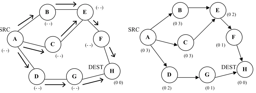
TORA [35] is a distributed routing algorithm based on the concept of link reversal. The protocol consists of three basic functions: Route Creation, Route Maintenance and Route Erasure [31]. For route creation and maintenance, nodes use a height and reference metric to establish a directed acyclic graph (DAG) rooted at the destination. Route creation is accomplished using QRY and UPD packets. The route creation process is initiated by broadcasting a QRY packet with the destination ID in it. The height of the destination is set to 0 and the height of all other nodes is set to null. A node with a non-null height responds to a QRY packet with a UPD packet. A node receiving an UPD packet sets its height to one more than the node that generated the packet. Thus, a node with higher height is considered upstream and a node with lower height is considered downstream. This technique permits the source to construct a DAG rooted at the destination. Each node discards a QRY packet if it has already seen the packet. A node always uses the least height offered by an UPD packet. The route creation process is illustrated below.
Figure 3.2: Route Creation in TORA
DEST SRC
DEST SRC
Propagation of QRY packets
(0 0) (- -) (- -) (- -) (- -) (- -) (- -) (- -) (0 0) (0 1) (0 1) (0 2) (0 3) (0 2) (0 3) (0 3) A B C D E F H G A B C D E F H G
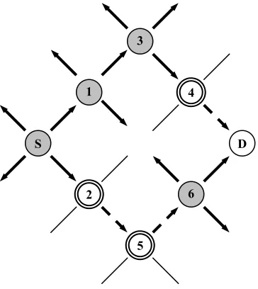
When a node moves, the DAG is broken and route maintenance is necessary to re-establish a DAG for the destination. When an upstream neighbor observes a link failure, it generates a new reference level. The neighboring nodes propagate the reference level and each node reverses its link to reflect the change in adapting to the new reference level. Each link reversal message is time stamped and this mechanism provides a network partition detection capability to TORA. The route maintenance mechanism is illustrated below.
Figure 3.3: Route Maintenance in TORA
In the route erasure phase, TORA floods a broadcast CLR packet throughout the network to erase invalid routes. TORA assumes that all the nodes have synchronized clocks and cannot function properly if the timing is unreliable. In addition, it suffers from temporary instability problems similar to the “count to infinity” problem in distance vector routing protocols.
3.1.7 Associativity Based Routing (ABR)
The Associativity Based Routing protocol [56] is a loop-free on-demand routing protocol based on the concept of association stability. Association stability refers to the connection stability of one node with respect to another node over space and time. ABR attempts to find long-lived routes to a destination based on associativity states of the nodes. All nodes generate periodic beacons to notify other nodes of their existence. Each node maintains an associativity table and updates its table when it receives a beacon from a neighboring node. For every beacon received, a node increments its associativity tick for the initiator of the
(1 0) Link E-F fails
Node E is the new reference level
(0 0) (0 1)
(0 1)
(1 -1)
(0 2) (1 -1)
(0 3)
A
B
C
D
E
F
beacon. Thus a high value of associativity tick indicates a low level of mobility, while a low value of associativity tick indicates high mobility. ABR consists of three basic mechanisms: Route Discovery, Route Reconstruction and Route Deletion.
In the route discovery phase, the source broadcasts a BQ message to the destination. On receiving a BQ message, an intermediate node appends its address and its associativity ticks to the query packet. Intermediate nodes do not forward the BQ packet more than once. The next node that receives the BQ packet retains only the entry concerned with itself and its upstream neighbor and erases the remaining information from the query packet. It then appends its address and associativity ticks and rebroadcasts the packet. Each BQ packet arriving at the destination thus contains the associativity ticks of the nodes along the route from the source to the destination. The destination chooses the route with the best associativity metric and responds with a REPLY packet by reversing the route. Nodes along the path mark their routes as valid.
3.1.8 Zone Routing Protocol (ZRP)
The Zone Routing Protocol [19] is a hybrid routing protocol that combines the merits of on-demand and proactive protocols. Each node chooses a parameter, referred to as the zone radius, in terms of radio hops. The routing zone of a node is defined as a collection of nodes whose distance from the node is no greater than the zone radius. For each node, the set of nodes that can be reached directly are called its neighbors and the set of nodes that are at a distance equal to its zone radius are called the peripheral nodes for its routing zone. Zones can overlap and do not have any master-slave relationship.
Within a routing zone, a proactive scheme is used and localized route updates are performed. These updates are performed using the Intrazone Routing Protocol (IARP) [18]. IARP can be implemented using existing link-state or distance vector protocols. It uses a neighbor discovery protocol to discover neighboring nodes and the status of links to these nodes. Thus each node has a route to every other node in its routing zone. When a node has a packet to be sent to a destination, it checks whether the destination is within its zone. If so, no further route discovery is required and the packet can be immediately forwarded to the destination. If the destination is outside a node’s routing zone, an on-demand route discovery mechanism is used. The Interzone Routing Protocol (IERP) [17] is used for this purpose. Instead of flooding the request, the node sends a request to all its peripheral nodes. This packet delivery service is called bodercasting [16]. The peripheral nodes check whether the destination is within their routing zone. If so, they send a reply to the source node, providing it with the desired route. Otherwise, they bodercast the request to their peripheral nodes.
Various other protocols have been proposed for routing in mobile ad hoc networks [49][59][31]. Table 3.2 lists few protocols that have not been covered in this section. These protocols have been categorized based on their type.
Proactive Protocols On-Demand Protocols
Wireless Routing Protocol (WRP)
Clusterhead Gateway Switch Routing (CGSR) Source Tree Adaptive Routing (STAR) [42] Landmark Routing Protocol (LANMAR)
Signal Stability Routing (SSR) Location Aided Routing (LAR) [27] Neighborhood Aware Source Routing [53]
Table 3.2: Other Protocols for Routing in MANET
3.2 Performance of Ad Hoc Routing Protocols
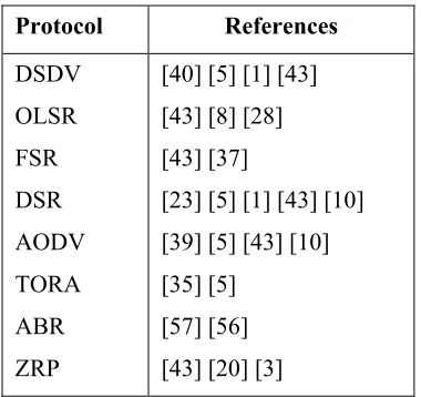
This section presents a discussion on the performance of the previously described ad hoc routing protocols. The observations are based on various studies that have been done to compare the performance of routing protocols for mobile ad hoc networks. Table 3.3 lists the references that have been used for each protocol under consideration.
Protocol References
DSDV OLSR FSR DSR AODV TORA ABR ZRP
[40] [5] [1] [43] [43] [8] [28] [43] [37]
[23] [5] [1] [43] [10] [39] [5] [43] [10] [35] [5]
[57] [56] [43] [20] [3]
3.2.1 Performance of DSDV
DSDV delivers about 92% of its packets when nodal mobility is low. As the mobility rate increases, DSDV performs poorly and its packet delivery ratio falls to about 70%. The high percentage of packet loss is due to the inability of the protocol to respond quickly to changes in the topology and many packets are dropped due to invalid routes. DSDV fails to converge at very high mobility rates. Due to the proactive nature of DSDV, the routing overhead of DSDV is a constant regardless of the mobility rate, which is good in terms of scalability. Also, the protocol finds routes that are close to optimal in most cases. The energy consumption in DSDV is very high compared to on-demand protocols like DSR and AODV due to the tremendous overhead incurred by DSDV in performing constant routing updates.
3.2.2 Performance of OLSR
3.2.3 Performance of FSR
FSR uses the fisheye scope concept to reduce flooding of control information. Increasing the number of scopes decreases the number of packets sent by flooding during link state updates. Reduction in routing overhead depends greatly on the number of fisheye scopes for a node. An 80% reduction in routing overhead can be achieved by using three scopes instead of one. If the number of scopes is beyond three, the reduction in overhead is not significant. Having multiple scopes can decrease the routing accuracy and degrade performance in highly mobile networks. This inaccuracy can cause many packets to be dropped and results in poor packet delivery ratio. Since FSR uses periodic broadcasts, the routing overhead is a constant regardless of load and mobility. When nodal mobility is less than 1 m/s, FSR delivers more than 80% of its packets. However, under high mobility conditions, the packet delivery ratio in FSR drops to 40%. The routing overhead in FSR decreases with increasing load and this makes the protocol scalable.
3.2.4 Performance of DSR
3.2.5 Performance of AODV
AODV performs very well in networks of up to 100 nodes regardless of node mobility and network load. Under these conditions, it delivers close to 95% of its packets and the throughput can approach 100% in fairly static networks. The throughput decreases as the number of nodes increases due to longer routes and higher collision rate. At 500 nodes, the throughput drops to 85% and at 1000 nodes, it drops to 70%. The packet delivery ratio also drops with increase in nodal mobility. The routing overhead is lower than proactive protocols but is high compared to DSR. However, AODV outperforms DSR in terms of per-packet overhead. As nodal mobility increases, the routing overhead increases exponentially. Under conditions of high mobility, high load and larger number of nodes, the throughput can drop to 70% and the ratio of routing bit per data bit can increase to 1.5. At low node speeds, the route acquisition time is a constant up to 100 nodes. However, the route acquisition latency triples for 1000 nodes. Unlike many protocols, AODV does not find the optimal route in most cases and the difference in the optimal route and the route found by AODV can be up to four hops. It is interesting to note that the average delay in AODV decreases as the mobility increases. The reason for this can be attributed to redistribution of network load when the network topology changes at a high rate. Due to route expiry, AODV does not have stale route problems unlike many routing protocols.
3.2.6 Performance of TORA
overhead compared to these protocols. The routing overhead in TORA is the sum of constant mobility-independent overhead (due to neighbor sensing) and variable mobility-dependent overhead. TORA was not designed to find optimal routes and in most cases, the routes found by TORA are 4 hops longer than the optimal route.
3.2.7 Performance of ABR
3.2.8 Performance of ZRP
Chapter 4
Unidirectional Links in Mobile Ad Hoc Networks
Unidirectional links can exist in a wireless environment due to a variety of reasons. A unidirectional link arises between a pair of nodes in a network when only one of the two nodes can directly communicate with the other node. Most routing protocols that have been proposed for mobile ad hoc networks assume that all the links in the network are bi-directional. They either fail to work or become highly inefficient in the presence of unidirectional links. In this chapter, we investigate the influence of unidirectional links on mobile ad hoc networks. First we discuss the causes for the presence of unidirectional links in an ad hoc network. Then we discuss the impact of unidirectional links impact on link layer and routing protocols. We present a case study on the performance of the Dynamic Source Routing protocol in the presence of unidirectional links. Finally, we look at some related work in the field.
Communication in a wireless medium is governed by the following equation: 2 s 2 r t t r R) (4π F λ G G P
P = (4.1)
where,
Pris the signal strength at the receiver Pt is the in-band transmit power Gt is the gain of the transmitter antenna Gr is the gain of the receiver antenna
λis the wavelength of communication given by λ = C / γ (γ being the frequency used)
Fs is the loss factor due to fading and multipath loss R is the distance between the transmitter and the receiver
The signal strength at the receiver can be expressed in terms of the receiver sensitivity. Receiver sensitivity is defined as the minimum input signal strength (Smin) that can be
perceived by the receiver. It depends on the Signal to Noise Ratio (S/N) of the receiver. The Signal to Noise Ratio is defined at the ratio of the signal power at the receiver and the Mean Noise Power of the receiver. All receivers require the signal power to exceed the noise power by a certain factor (S/N)min. If the signal power is equal to or less than the noise power, the
signal cannot be detected. Noise at the receiver is a combination of the accumulated noise and the background noise.
= = Power Noise Mean Power Received S/N n n B A Power Received
+ (4.2)
An is the accumulated noise at the receiver given by the equation An=kToB(NF), where
k is the Boltzmann's Constant = 1.38 x 10⁻²³ Joule/°K
To is absolute temperature of the receiver input (in °Kelvin)
B is the receiver bandwidth (in Hz)
NF is the noise figure of the receiver
In the above equation, kToB is the thermal noise and (NF) is the noise accumulated due to the
technology used to build the receiver. Bn is the background noise due to external sources like
channel interference. Given the accumulated noise and the background noise, the receiver sensitivity can be expressed as
Smin = (S/N)min (An + Bn) (4.3)
Using equations (4.1) and (4.3), we can derive an equation for the transmission range of a node. 2 s n n min 2 t t s min 2 r t t ) (4 F ) B (A (S/N) λ Gr G P 4 F S λ G G P R π π = + = 2 )
( (4.4)
From equation (4.4) we note that the range depends on the following factors that can contribute to the formation of unidirectional links in an ad hoc network:
1. The transmit power and receiver sensitivity
2. The antenna characteristics of the transmitter and receiver 3. The noise level at the receiver node
4.1.1 Disparity in Transmit Power and Receiver Sensitivity
Figure 4.1: Unidirectional Link Due to Disparity in Transmission Range
Now let us consider a numerical example. Consider two nodes, A and B, operating in the 2.4 GHz ISM band having isotropic antenna gains (Gt = Gr = 1) and a sensitivity of -80dbm1.
Let the transmit power of the first node be equal to 5 mW and the transmit power of the second node be equal to 50 mW. Assuming a unity loss factor and uniform noise level at both the nodes, we can find the transmission range of the nodes using equation (4.4).
γ = 2.4 GHz ∴λ = 0.125 m Sensitivity = -80 dbm = 10-11 W
RangeA = 2 x 11 2 x x 3 x 16π 10 (0.125) 1 10 5 − −
= 222.4 m
RangeB = 2 x 11 2 x x 3 x 16π 10 (0.125) 1 10 50 − −
= 703.4 m
1 mW 1 atts) W (in P 10 log 10 dbm =
R1 > R2
R2
R1
A
If node A is within 700 meters of node B, node B can communicate directly with A but node A cannot reach B leading to the formation of a unidirectional link between A and B. When the nodes in an ad hoc network have different transmit powers, the presence of unidirectional links in the network can be quiet common. A typical example is a battlefield scenario composed of high-powered vehicle mounted nodes and low-powered hand-held nodes.
It can be seen from equation (4.4) that the transmission range is a function of the receiver sensitivity. As discussed, the receiver sensitivity depends on the RF technology used to build the receiver. It is a well-known fact that a –6dbm increase in the receiver sensitivity doubles the range. When a wireless network is composed of heterogeneous nodes with varying receiver sensitivities it is possible to have permanent unidirectional links in the network.
Power is an extremely critical resource in mobile networks. Each node has limited battery life that allows it to remain operational for a few hours. Varying the transmission power and hence the transmission range is a powerful and well-explored [15] technique for conserving battery power. It is interesting to note that commercially available wireless cards like the Cisco Aeronet Series cards [7] support multiple transmit powers. The nodes in an ad hoc network may employ individual power control algorithms to stay operational for a longer period of time. Power control algorithms that support variable power levels at each node [46] can lead to the formation of permanent unidirectional links in the network.
4.1.2 Disparity in Antenna Characteristics
the performance of a theoretical isotropic antenna that radiates equally in all directions. By definition, an isotropic reference antenna has unity gain.
Beam-forming antennas typically tend to have a higher gain in the direction of transmission. Thus they can cover a larger distance for a given transmit power. Disparity in antenna characteristics can lead to the formation of unidirectional links in an ad hoc network. For example consider two nodes A and B. Node A uses a beam-forming technique for transmission with a gain Gt. In the receive mode it uses an isotropic antenna pattern with a
gain Gr = 1. Here Gt > Gr. Thus, node A has asymmetric gains in the transmit and receive
modes. Node B uses an isotropic antenna with equal gains in both the modes. Assuming uniform transmit power, sensitivity and noise level at both the nodes, for a given operational frequency, node A can cover a longer distance than node B due to the higher gain in the transmit mode. Thus, Node A might be able to send signals to node B but not receive signals from B leading to the formation of a unidirectional link between A and B. Figure 4.2 illustrates this scenario.
Figure 4.2: Unidirectional Link Due to Disparity in Antenna Characteristics
4.1.3 Disparity in Noise Levels at the Receiver Node
As discussed in the previous section, the noise level at the receiver node is a combination of the accumulated noise and the background noise. The accumulated noise is typically uniform for all nodes operating at a given frequency. However, the background noise due to channel
Gains are equal in both modes Range = R3
Transmit mode gain Gt > Receive mode gain Gr
Transmit mode range R2 > Receive mode range R1
R3
R2
Directed Beam
A B
interference is variable. From equation (4.4) it can be seen that, for a given signal to noise ratio and accumulated noise, an increase in the background noise decreases the sensitivity of the receiver. Given two nodes with the same transmit power levels and antenna characteristics, the received signal strength at a node with a higher noise level can be significantly lower than at a node with a lower noise level. Thus the noise level around a receiver has a direct impact on the link quality. This asymmetry in noise levels can lead to the formation of unidirectional links in the network. However, unidirectional links formed in this way tend to be temporary due to the transient nature of the background noise. A unidirectional link formed between a pair of nodes due to excessive noise at one of the nodes can start working well in both directions after some time due to a decrease in the noise level. Nodes may experience different levels of interference due to wireless channel limitations like fading and multipath loss. In addition, the hidden terminal problem can cause variations in the interference levels. The duration for which a link remains unidirectional due to interference is a function of the terrain, offered traffic and the mobility pattern of the nodes.
4.2 Impact of Unidirectional Links
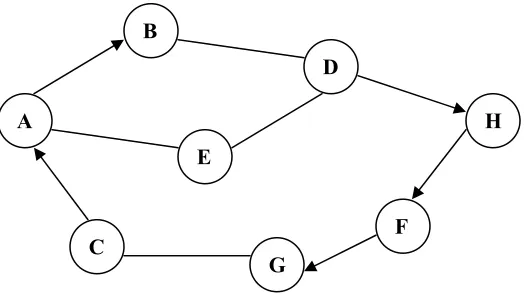
Figure 4.3: Ad Hoc Network with Unidirectional Links
The presence of unidirectional links affects the following layers in the protocol stack: 1. The Data Link Layer
2. The Network Layer
4.2.1 Impact of Unidirectional Links on Link Layer Protocols
Many link layer protocols use a two-way handshake mechanism to overcome the hidden terminal problem. The hidden terminal problem is illustrated in Figure 4.4.
Figure 4.4: Hidden Terminal Problem
Consider three wireless nodes A, B and C. The transmission/reception range of A reaches B but not C. Similarly C can communicate with B but not with A. Node B can communicate with both A and C. When A starts sending data to B, the transmission will not be heard by C. If C also wants to send data to B, it will sense the medium as idle and immediately start sending data to B causing collisions at B. Thus, A is hidden for C and vice versa.
A
A
B
E
C
D
F G
H
The well-known IEEE DCF MAC protocol [21] and other medium access protocols like MACA [25] operate only over bi-directional links. They use the RTS-CTS exchange mechanism to prevent collisions due to the hidden terminal problem. This technique is illustrated in Figure 4.5. The sender sends an RTS (Request to Send) packet to the receiver and expects a CTS (Clear to Send) packet in return before data transmission can begin. The receiver sends a CTS packet only if it is not busy. The RTS-CTS exchange serves two purposes - it notifies the sender that the receiver is ready to receive data and it informs all the nodes in the vicinity of the sender and the receiver about the impending data transfer. Thus it is possible to avoid collisions due to the hidden terminal problem.
Figure 4.5: The RTS-CTS Exchange Mechanism
However, when the link between the sender and the receiver is unidirectional, it is not possible to exchange CTS packets. If all data communication is preceded by an RTS-CTS exchange, then a pair of nodes having a unidirectional link between them cannot exchange data. To overcome this problem, the RTS-CTS exchange can be disabled leading to a possible increase in packet loss due to collisions. This entails the need for a robust transport layer protocol in MANETs with unidirectional links. Also, many MAC protocols including 802.11 use link-level acknowledgments for unicast data transmission. The receiver is expected to acknowledge the receipt of each packet. Otherwise, the sender assumes that the packet was lost and retransmits the packet. If the link between the sender and the receiver is unidirectional, acknowledgements sent by the receiver may not reach the sender. Thus, the sender will timeout and after a specific number of retransmissions, conclude that the link between itself and the receiver is down.
CTS RTS
A B C
CTS
CTS RTS
A B C
CTS
A CTS B C
RTS
4.2.2
Impact of Unidirectional Links on Routing Protocols
Most routing protocols for ad hoc networks assume that all the links in the networks are bi-directional. When these protocols are used in network composed of nodes with dissimilar transmission ranges, they will always try to find links between two nodes having the same transmission range. Though communication might be possible between a source and a destination through two asymmetric paths, the source node will consider the destination to be unreachable if it does not have a symmetric path to the destination. Also, all nodes in the network have to maintain relatively constant power consumption to ensure that their transmission and reception ranges are not affected. At the routing layer, the influence of unidirectional links is two-fold. Many ad hoc routing protocols use a link reversal or path reversal mechanism for their operation. For example AODV [39] floods a RREQ packet for route discovery that records the set of all nodes in the path from the source to the destination. When the destination receives the RREQ packet, it reverses the list of nodes recorded in the RREQ to send a RREP (route reply packet) to the source. However, even if one of the links in the path from the source to the destination were unidirectional, this judgment would be wrong. Thus the fact that the source can reach the destination does not imply that the destination can reach the source by reversing the path. This is called Routing Asymmetry and can be stated as follows:
“Suppose the path from Node X to Node Y is X-v1-v2-v3-v4-Y, the path from Y to X cannot
be assumed to be Y-v4-v3-v2-v1-X”.
beacon from another node, it considers the originator of the beacon to be a neighbor and adds the node’s address to its neighbor list. Each node includes the neighbor list in its beacons. Thus, if a node finds its own address in the neighbor list recorded in a beacon, it will know that it has a bi-directional link with the neighboring node. However, periodic beaconing suffers from high overheads and has serious impact on the degradation of battery life. In addition, it may lead to an increase in the number of collisions making it unfeasible for dense networks.
Another consequence of the presence of unidirectional links in ad hoc networks is the failure of the hop-level acknowledgement technique for route maintenance. Many ad hoc routing protocols rely on hop-level acknowledgments for detecting route failures. Each node along the path from the source to the destination is required to confirm the receipt of the packet at the next hop node along the path. If the next hop node fails to acknowledge the packet, the upstream node concludes that the link is broken and sends a route error notification to the source node. Three techniques have been employed for obtaining hop-level acknowledgments.
The sender requests an explicit network layer acknowledgment from the receiver
The sender operates in the promiscuous listen mode and confirms the receipt of the packet at the receiver when the receiver transmits the packet to the next hop node along the path.
The routing protocol relies on link-level acknowledgements from the link layer protocol to confirm the reachability of the next hop node.
4.3 DSR and Unidirectional Links: A Case Study
DSR is one among the very few ad-hoc routing protocols that considers the possibility of unidirectional links in the network. Though the DSR draft [24] mentions some of the problems associated with unidirectional links in ad hoc networks, no detailed mechanism has been presented for handling unidirectional links. All simulations that have been done to evaluate the performance of DSR assume that the links in the network are bi-directional and use the path reversal technique for route establishment. Also, the simulations have been done using an 802.11 MAC protocol [21] at the link layer. The link layer acknowledgments, provided by the MAC protocol, are used for route maintenance. No proper study has been done to evaluate the performance of DSR in the presence of unidirectional links. In this section, we analyze the shortcomings of DSR when used in mobile ad hoc networks with unidirectional links.
DSR has no auto-discovery feature to detect the presence of unidirectional links. The protocol has to be explicitly configured for the presence of unidirectional links. When DSR is configured for bi-directional links, the protocol always tries to find bi-directional paths and avoids the use of unidirectional links for routing. Thus, communication can fail even if a bi-directional channel exists between the source and destination. In ad hoc networks with unidirectional links, the performance of DSR degrades due to a variety of problems and the protocol becomes highly inefficient. We shall look into these problems in more detail in the following sections.
4.3.1 Route Request Storms
storms, each node having a cached route to the destination delays its reply by an amount proportional to the length of the cached route and listens to check if the source begins using another route. A node cancels its reply when it infers that the initiator has already received a reply. For this optimization to work, the nodes have to enable promiscuous receive mode on their network interface hardware. Use of promiscuous mode may increase the power consumption and some nodes may not be able to switch their interface to a promiscuous listen mode. In addition, this mechanism does not prevent route reply storms if nodes cannot hear the transmission from the source to the destination. This is a major problem in DSR even if all the links in the network are bi-directional. However, the inefficiency of the protocol comes to light when unidirectional links are considered.
Consider the network configuration shown in Figure 4.6.
Figure 4.6: DSR Route Discovery in Ad Hoc Networks with Unidirectional Links
Node A attempts to discover a route to node G by broadcasting a route request packet. When nodes B and F receive this route request from A, they attempt to send a route reply back to A. However, they cannot reverse the path recorded in the route request packet to reach A. Thus each of these nodes initiates a route request to establish a path to A and piggybacks the route
Route Request (A)
A
B
D
C
E
G
F
G BEG
G FG Route Request (A)
Route Request (A)
reply on the route request packet. In addition, the destination G can initiate a route request when it receives the route request from A. Thus a single route request can trigger a Route
Request Broadcast Storm. Such a high number of broadcasts not only reduces the network
bandwidth but also leads to an increase in the number of network collisions. The situation becomes worse in dense ad hoc networks with many nodes talking to each other. In such networks, it may so happen that the entire network bandwidth is spent is establishing routes between the nodes. If the reply from node B reaches node A before the replies from nodes F and G, node A will end up using the stale route returned by B. Also, the shortest path from A to G is ADG. However, if A gets a reply from F before it learns about this shortest path through another reply, it will end up using as route with 3 hops. In conclusion, the route request process in DSR can prove to be extremely costly in ad hoc networks with unidirectional links.
4.3.2 Route Maintenance and Chain Reactions
DSR relies on hop-level acknowledgements for route maintenance. This entails the need for a bi-directional channel of communication between each pair of adjacent nodes in the route from the source to the destination. In addition to forwarding packets, each node is responsible for keeping track of route failures. This mechanism can lead to route maintenance broadcast storms in the DSR. As an example consider Figure 4.7.
Figure 4.7: DSR Route Maintenance in the Presence of Unidirectional Links
Node A uses the path ABCDE to reach destination E. Whenever A sends a packet to E, each node along the path is required to confirm the receipt of the packet at the next downstream
Link DE has failed
A B C D E
Route Request (A) + Route Error Route Request (B)
Route Request (A)
E ABCDE
neighbor along the route. Suppose, B does not have a route to A and C does not have a cached route to B, a packet transmission from A to E can trigger route request broadcasts at B and C and at each node along the path from A to E. The problem aggravates when an intermediate node detects a link failure. When node D detects that the link DE has failed, it propagates a route error packet to the source to inform it about the failure. If E does not have a cached route to A, it initiates another route request. The source node, after learning about the route failure, may initiate a fresh route request to discover a new route to E. Each broadcast can trigger route request storms as explained in the previous section and each route once established, can lead to broadcasts due to route maintenance thus leading to a chain reaction. These chain reactions waste network bandwidth, can cause congestion in the network and can lead to an unacceptable number of packet collisions making the protocol highly inefficient in ad hoc networks with unidirectional links. In addition, these chain reactions can place an unnecessary load on the nodes in terms power consumption.
4.3.3 Caching
Nodes using DSR cache source routes when they forward a data packet, route request or route reply. Additional optimizations like promiscuous sniffing have been proposed to make caching efficient. Nodes can enable promiscuous listen mode on the network interface hardware and cache routes by listening to packet transmissions between other nodes in their vicinity. However, presence of unidirectional links in the network has a big impact on the caching policy. In order to illustrate the problems, consider the network configuration shown in Figure 4.8.
Figure 4.8: DSR Caching in the Presence of Unidirectional Links
Route Error
A B C D
G F
E
Route Error
Route Error
Due to routing asymmetry, whenever nodes forward packets, they can only cache the forward route to the destination and not the reverse route back to the source node. In Figure 4.8, when a node G overhears a packet transmission from node B to node C, it cannot cache a route to nodes C, D and E through B because the link between B and G is unidirectional. Thus, nodes cannot adopt a “cache whatever you hear” policy by switching their network hardware to promiscuous listen mode.
Once a route is cached, the entry is flushed when the entry exceeds its cache lifetime or when the node learns about a route failure. When path reversal is used for propagating route error packets, nodes along the route can learn about the link failures and flush stale routes from their cache. However, in the presence of unidirectional links, path reversal cannot be used and nodes may never learn about link failures. Thus they can end up caching routes that do not work. In Figure 4.8, nodes B and C may never learn about the failure of link DE unless the source node A informs them about the failure. Presence of stale routes can lead to routing nightmares in DSR. Intermediate nodes with stale routes to the destination can send corrupted route replies to the originator leading to path failures and associated chain reactions, as explained in the previous section. One optimization that has been proposed to overcome this problem involves piggybacking of route error information on route request packets. However, this solution increases the per-packet overhead and many not work well in all situations.
4.4 Related
Work
Chapter 5
The Terminal Node Controlled Routing Protocol
5.1 Introduction
Most routing protocols for ad hoc networks assume that all the links in the network are bi-directional. However, permanent unidirectional links can exist in the ad hoc network when the network is composed of nodes with heterogeneous characteristics. Existing protocols for routing in mobile ad hoc network either fail to work or become highly inefficient in the presence of unidirectional links. Solutions that have been proposed for handling unidirectional links are modifications to existing routing protocols that avoid unidirectional links in routing paths and involve high overheads for detecting unidirectional links and maintaining bi-directional paths. In this chapter we propose and discuss a new routing protocol, the Terminal Node Controlled Routing Protocol (TNCR), for mobile ad hoc networks. The primary goal of the protocol is to provide an efficient, link layer independent mechanism for routing in ad hoc networks in the presence of unidirectional links. In addition, the protocol can operate in a directional mode in which it takes advantage of the bi-directional nature of the links in the network for additional optimizations. The protocol is best suited for ad hoc networks composed of nodes with heterogeneous transmission characteristics.