Digital PWM Techniques and Commutation
for Brushless DC Motor Control Applications:
Review
Prof. S.L. Tade1, Ravindra Sor2 & S.V. Kinkar3
Professor, Dept. of E&TC, PCCOE, Pune, India1
Scientist, ARDE-DRDO, Pune, India2
PG Student [VLSI], Dept. of E&TC, PCCOE, Pune, India3
ABSTRACT:Brushless DC motor has gained popularity over a broad range of motion controller applications. The 3-phase permanent magnet BLDC motor inherently needs an electronic commutation circuit to drive it as it is not a self-commutating motor. Unlike to the conventional brush motor this commutates itself. This paper introduces the principle of the operation of 3-phase BLDC motor and briefly explains three commutation methods for BLDC motor i.e. Trapezoidal, Sinusoidal and Field oriented control method. Also introduces three different methods of digital PWM techniques.
KEYWORDS: BLDC motor, Digital PWM technique.
I.INTRODUCTION
Nowadays numerous motors extensively used in the automobile application, defence application and in white goods. These motors are intended to have a small size, light weight, high power density and to be eco-friendly. Among various motors, brushless DC motor (BLDC) is one of the most used motors to meet above demands.
BLDC motor have gained a rapid adoption in the market and over a broad range of motion control applications due to the specific benefits they have over traditional brushed DC motors such as less maintenance, higher operating speed, high efficiency, robust operation, compactness, less electrical noise and better torque to weight ratios[5]. BLDC motor is a type of permanent magnet synchronous motors. The dc voltage drives it, and solid state switches do current commutation. As due to the absence of mechanical commutator and brushes undesirable effects such as sparks, carbon particles and acoustic noise coming from brushes are eliminated. Despite this advantage, BLDC motor is costly than traditional DC motors since it require a motor drive controller (electronic commutation) plus a rotor position sensor. The cost issue of BLDC motor is overcoming due to new trends in the design of BLDC motor drives.
A BLDC motor uses position sensors and an inverter to control the armature currents. There are two main types of permanent magnet synchronous motors based on their shape of waveforms of back Electro-Motive Force (EMF). Permanent magnet synchronous motors with sinusoidal shape wave back-EMF are known as Permanent Magnet Synchronous AC Motors (PMSMs) and the other type with trapezoidal shape wave back-EMF are known as Permanent Magnet Brushless DC (BLDC) Motors. BLDC motors produce larger torque compared to PMSMs.
and control algorithms complexity are the main drawbacks of sensorless BLDC motor drive [2]. Therefore sensorless drives require a starting algorithm to speed up the BLDC motor to a level that is able to sense back EMF.
II.BASIC OPERATION OF BLDC MOTOR
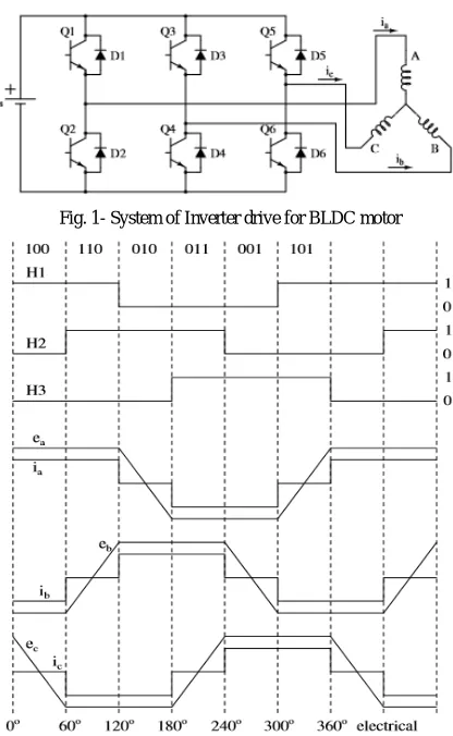
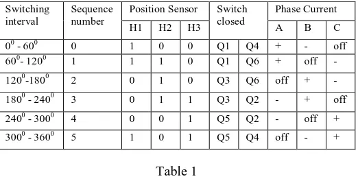
Figure 1 shows inverter drive system for BLDC motor. It consists of a three phase inverter composed of switches that could be insulated-gate bipolar transistors (IGBTs) or MOSFETs. If MOSFETs are used, body diodes are to be connected across switch while if IGBTs are used then, anti-parallel diodes are to be connected for carrying reverse currents. MOSFETs give lower turn-off switching loss and usually lower diode forward drop, but that advantage may be offset by higher ON-state voltage drop and turn-on switching/diode reverse recovery loss than IGBTs. The three phases BLDC motor is operated in a two-phases ON fashion i.e. two phases that produce the highest torque are energized while the third phase is kept OFF. Depending on rotor position two phases are energized. From the position sensors, a three digit number signal is produced that changes every 600 (electrical degrees). Fig.2 shows ideal current and back-emf waveforms. Current commutation is done by a six step inverter as shown in fig. The Table shows the switching interval, the phase current, and the position sensor signals. In order to obtain constant output power and thus a constant output torque, current is driven through a motor winding during the flat portion of the back-EMF waveform. [6]
Speed is directly proportional to the applied voltage across the motor phases of BLDC motor. This can be achieved by using a sensor method based on the pulse width modulation, PWM, or hysteresis control [6]. A common control algorithm for a permanent-magnet BLDC motor is PWM current control. It is based on the assumption of a linear relationship between the torque and the phase current, similar to that in a brushed dc motor. Therefore, the electromagnetic torque can be controlled by adjusting the phase current to meet the requirement [8].
Fig. 1- System of Inverter drive for BLDC motor
Table 1 shows the switching sequence, the current direction and the position of the back-EMF waveform.
Table 1
III. THREE TYPES OF COMMUTATION METHOD
As the BLDC motor is brush free, commutation is done electronically. For commutation exact rotor position is required. In this paper, the rotor position is detected through Hall Effect sensor is considered. The widely used commutation methods for the BLDC motor are trapezoidal (or six-step), sinusoidal and field oriented control (FOC) (also known as vectorial control). A different algorithm is used to implement these individual commutation methods.
A. Trapezoidal Commutation
The Hall-effect sensor is mostly used for the sensing position of the rotor in this commutation. Because of the simple control algorithm, this method is very popular. It results in the flat peak trapezoidal waveform. In this method, torque production follows the principle that current should flow in only two of the three phases at a time and that there should be no torque production in the region of Back EMF zero crossings. One of the characteristic of the BLDC motor control is to have only one current at a time (i.e. two phases ON). Consequently, it is not necessary to put a current sensor on each phase of the motor; one sensor placed in the line inverter input makes it possible to control the current of each phase.
Fig. 2 describes the electrical waveforms in two phases ON operation fashion. The principle of BLDC motor is to energize the pair of the phases which produces the highest torque. The combination of a trapezoidal back emf with a DC current makes it possible to produce a constant torque, theoretically. But in practice instantaneously current cannot be produced in motor phase and as a result torque ripple is established at each 60-degree phase commutation. Uses six step sequence to get rotor position information. It effectively controls motor speed but as discussed suffers from torque ripple at low speed. The 180-degree commutation method is chosen to generate high torque but for minimum torque ripple, 120-degree commutation should be chosen.
B. Sinusoidal Commutation
In this commutation method, flat peak is replaced with sinusoidal waveforms that match perfectly to the back emf. Trapezoidal commutation is insufficient to provide smooth and precise motor control of brushless dc motors, especially at low speeds. Sinusoidal commutation solves this issue. BLDC motor with sinusoidal commutation drives three motor windings with three currents which vary sinusoidally and smoothly as the motor runs. The current phases are chosen so that they results in a smooth rotating current that has constant magnitude and is always in the quadrature direction with respect to the rotor. This eliminates the commutation spikes and the torque ripple associated with trapezoidal commutation.
An accurate measure of rotor position is required. But the hall devices provide only a rough measure and are insufficient for this purpose. So for this, high-resolution position feedback devices as encoder are required. That makes it more expensive than the trapezoidal commutation method. It can be operated as a closed or open loop configuration using a speed feedback sensor. In closed loop operation, the Commutation Table Position is updated from the Feedback Position. In open loop operation, the Command Position provides the link that updates the Commutation Table Position and consequently moves the motor.
Switching interval
Sequence number
Position Sensor Switch closed
Phase Current
H1 H2 H3 A B C
00 - 600 0 1 0 0 Q1 Q4 + - off
600- 1200 1 1 1 0 Q1 Q6 + off -
1200-1800 2 0 1 0 Q3 Q6 off + -
1800 - 2400 3 0 1 1 Q3 Q2 - + off
2400 - 3000 4 0 0 1 Q5 Q2 - off +
C. Field oriented control commutation
It is best suitable for the high-end application due to its complex design and higher processing requirements. It commutates the motor by calculating current and voltage vectors based on motor current feedback. It allows for precise dynamic control of torque and speed and also maintains high efficiency over a wide operating range. It provides better efficiency than sinusoidal method at higher speeds. The method is used in variable speed or frequency drivers to control the torque of 3-phase BLDC motor by controlling the current. FOC provides the flux and torque controlled independently.
Comparison between characteristics of three different commutation methods is shown in Table 2 below
Commutation Method
Feedback device
Algorithm complexity
Speed control
Torque control Trapezoidal Hall
sensor, Encoder
Low Excellent Efficient
Sinusoidal Encoder, Resolver
Medium Excellent Inefficient
FOC Current
senor
High Excellent Excellent
Table2
IV. PWM CONTROL DRIVE SCHEMES
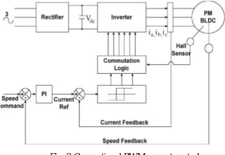
The conventional method proposed in [8] the general structure of a current controller for a BLDC motor is shown in Fig. 3. Instantaneous current in the motor is regulated in each phase by a hysteresis regulator, which maintains the current within adjustable limits. The rotor position information is sensed to enable commutation logic, which has six outputs to control the upper and lower phase leg power switches. The current reference is calculated by a PI regulator, which maintains the rotor average speed constant.
Fig. 3 Conventional PWM current control
Fig.4 Digital controller
We can also say that, the digital controller essentially generates PWM signals and converts them into commutation functions for the inverter switches based on feedback obtained for the speed regulator[7] Digital control algorithm is basic and takes actual speed, and reference speed as two inputs and the output is PWM logic signal for gate driver of the inverter switches. Such PWM voltage control is simple to put into practice; however, it is advisable to include over current protection to ensure the safe operation of the machine in the form of a dc-link current sensor. [9]
In 2015 [1] author proposed, the speed of the motor is sensed through Hall Effect signals and also proposed a novel algorithm to implement a closed loop PWM speed controller using FPGA for BLDC motors as shown in fig.5 [1]. Increases or decreases the PWM duty cycle signal based on the speed error. Therefore in the ideal case only one duty cycle, D is determined by the controller for any particular reference speed (0≤D≤1). A proportional integral (PI)
controller is used to determine PWM duty cycle signal according to speed error. The PWM duty cycle is changed based on a pre-defined value. One percent change of the duty cycle value is chosen for increase/decrease steps in this study. The given FPGA-based PWM controller in this paper can determine the duty cycle value and changes the PWM duty cycle according to the error instead of changing the duty cycle value between two predetermined states. Thus, these technique increases the efficiency of the BLDC motor control drive. The algorithm presented in this paper is simple, and the performance of the BLDC motor PWM speed controller using FPGA is improved as compared to the above two mention schemes. This motor drive has more smooth speed response.
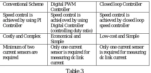
Table 3 shows the comparison between above three techniques:
Table 3
V. CONCLUSION
Digital control of BLDC machine has several benefits which include simple implementation, a requirement of no additional hardware and not computationally intense. Owing to this, the technique can be implemented on a microcontroller or an FPGA. Three different techniques are explained in this paper. The third scheme BLDC motor PWM speed controller using FPGA is more efficient and gives more smooth speed response.
REFERENCES
[1] A. Tashakori, M. Hassanudeen and M. Ektesabi, “FPGA Based Controller Drive of BLDC Motor Using Digital PWM Technique”,IEEE PEDS, 2015.
[2] A. Tashakori and M. Ektesabi, “Stability analysis of sensorless bldc motor drive using digital pwm technique for electric vehicles,” in Proceeding of 38th Annual Conference on IEEE Industrial Electronics Society, IECON 2012, pp. 4898–4903, October 2012.
[3] P. Damodharan and K. Vasudevan, “Sensorless brushless dc motor drive based on the zero-crossing detection of back electromotive force (emf) from the line voltage difference,” IEEE Transactions on Energy Conversion, vol. 25, no. 3, pp. 661–668, 2010.
[4] T.-H. Kim and M. Ehsani, “Sensorless control of the bldc motors from near-zero to high speeds,” IEEE Transactions on Power Electronics, vol. 19, no. 6, pp. 1635–1645, 2004.
[5] A. Tashakori and M. Ektesabi, “Comparison of different pwm switching modes of bldc motor as drive train of electric vehicles,” World Academy of Science, Engineering and Technology, vol. 67, pp. 719–725, 2012.
[6] A. b. Sathyan, N. Milivojevic, Y.-J. Lee, M. Krishnamurthy, and A. Emadi, “An fpga-based novel digital pwm control scheme for bldc motor drives,” IEEE Transactions on Industrial Electronics, vol. 56, no. 8, pp. 3040–3049, 2009
[7] Alphonsa Roslin Paul and Mary George, “Brushless DC Motor Control Using Digital PWM Techniques”, International Conference on Signal Processing, Communication, Computing and Networking Technologies (ICSCCN 2011).
[8] Z.Q.Zhu, Y.Liu and D.Howe, “Comparison of performance of brushless DC drives under direct torque control and PWM current control,” in Proc. 8th Int. Conf. Elect. Mach. Syst., Sep. 2005, vol. 2, pp. 1486–1491.
[9] Srinivasan. R, Vinoth. R, Vimala. D , Vinoth. D and Ravindar. S, “ Stability Analysis of ARM-Based Control of Brushless DC Motors Using Digital PWM Technique”, International Journal of Advanced Research in Electronics and Communication Engineering (IJARECE) Volume 2, Issue 11, November 2013.
Conventional Scheme Digital PWM Controller
Closed loop Controller
Speed control is achieved by using PI Controller
Speed control is achie[oved by using Digital Controller (controlling duty ratio)
Speed control is achieved by closed loop speed controller
Costly and Complex Economical and Simple
Low-cost and Simple
Minimum of two current sensors are required
Only one current sensor is required for measuring dc link current