2232
Design & Experimental Analysis of Multi Turn PHP
N.SanthiSree 1*, N V S S Sudheer2, P.Bhramara 3
Department of Mechanical Engineering 1,2,3,,Institute of Aeronautical Engineering1, RVRJC College of
Engineering2, JNTU Hyderabad3.
Email:
[email protected], [email protected]2, [email protected]3Abstract-Thermal management has become an important criterion and many devices have come up for this
purpose. The development of Pulsating Heat pipe (PHP) is able to meet present day requirements of cooling applications. PHP consists of an evaporator, an adiabatic zone and a condenser has major sections. The transfer of heat takes place by absorption of heat from the evaporator side by the working fluid and dissipating it at the condenser side through latent heat. Different thermodynamic characteristics which define performance of the PHP’s are the diameter of the pipe, working fluid, filling ratio, heat flux, orientation etc. In the present study the PHP with multiple turns has been modeled in CATIA and then fabricated accordingly. The pipes are of 4mm inner diameter and 6 mm outer diameter is made of copper in which water is filled as the working fluid. The filling ratio is 60%.Heat input is varied from 150 to 240 Watts. From the experimental results thermal resistance is calculated. The results show that with the increase of heat input thermal resistance value decreases.
Index Terms- Adiabatic Zone, Condenser, Evaporator, Heat Input, PHP, Thermal Resistance, Working Fluid
1. INTRODUCTION
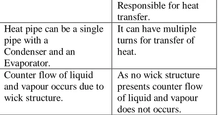
Now a day’s thermal management has become an important criterion in various fields like space, electrical and electronics, air-conditioning and solar systems etc. The heat transfer devices were developed in the 1960’s and since then has been constantly studied. Closed loop pulsating heat pipe [1] differs from that of conventional heat pipe with respect to its construction and mechanisms of transferring heat. A conventional heat pipe combines both the principles of thermal conductivity and phase transition to effectively manage transfer of heat between two surfaces. A heat pipe consists of a sealed tube which is usually made of a material having high thermal conductivity like copper, aluminium.[2] Inside the pipe for capillary action wicked structures are used. A suitable working fluid is filled inside the tube after evacuation. PHP does not contain any wick structure in it so there is no return of the working fluid from condenser to evaporator. A PHP consists of a tube which is structured in a serpentine manner with a number of turns. The heating of the working fluid in the evaporator leads to the creation of vapour bubbles and ultimately slugs and plugs which give rise to heat transfer [4]. The differences between conventional and pulsating heat pipe are detailed in below table1.
Table 1.Comparision between Conventional and Pulsating heat pipe
CONVENTIONL HEAT PIPE
PULSATING HEAT PIPE
It contains wick structure for heat transfer.
Slugs and plugs cause transfer of heat. Conduction and phase
transfer are responsible for transfer of heat.
Conduction and
It can have multiple turns for transfer of heat.
Counter flow of liquid and vapour occurs due to wick structure.
As no wick structure presents counter flow of liquid and vapour does not occurs.
Pulsating heat pipes are mainly closed loop and open loop structures [3]. In an open loop pulsating heat pipe, one end of the PHP is open while the other end is open for charge. Whereas the closed loop is an endless tube and it’s both ends are welded together .The working fluid is continuously circulated through the fluid. They are mainly guided by the chaotic slug/plug motion. In the present study a closed loop pulsating heat pipe with multi turns has been designed using CATIA and is fabricated by using different manufacturing techniques.
1.1 Parameters Affecting the Functioning Of Php
The performance of PHP will be influenced by the following parameters [3, 4]
1. Internal diameter of the pipe 2. Heat input
3. Working fluid 4. Filling ratio 5. Orientation of tubes 6. Number of tubes
2233
The pulsating action in the CLPHP is possible only to a certain range of internal diameter values.
The design rule is given by the critical bond number criterion.
(Eӧ) critical = (Bo) 2critical≈ [D2critical. g. (ρliq - ρvapor)]/σ ≈4
Dcritical≈ 2√ [σ/ (g (ρliq- ρvapor))]
Eӧ:Eötvös Number Bo: Bond Number
D: Internal diameter of tube g: Acceleration due to gravity ρ: Density
σ: Specific gravity
By the following this criterion, there is no possibility of agglomeration of vapour bubbles. So the liquid plugs and vapour slugs are continually maintained. If diameter is increased beyond the critical diameter, the device will start acting like an interconnected array of two phase thermo syphon [6]. Reducing the diameter below its critical diameter value effects the performance of device.
1.1.2 Heat Input
Heat input directly affects the performance of PHP. The pressure difference inside the tube is due to slug and plugs increases with higher heat flux rates. Dynamics of bubbles formed inside the tube, size of the bubble and agglomeration of bubbles are some of the effects of heat input.
1.1.3 Working Fluid
The two phase flow in CLPHP is mainly dependent on the working fluid used. From evaporator to condenser to carry the given heat input the fluid must be having a high thermal conductivity. Formation of bubbles increases with low latent heat fluids. The property Surface tension should be as low as possible for a stable flow. Liquid and vapour viscosities should be low. The fluid should be compatible with tube material.
1.1.4 Filling Ratio
For better working of CLPHP s, the tube must be partially filled. Filling ratio of PHP is the ratio of volume of working fluid in the device to the total device volume. In the present analysis 60% filling ratio is considered. CLPHP’s will be working at 40 to 60% of filling ratio [8-9]. High percentages causes formation of few bubbles only.
1.1.5 Orientation of Tubes
Horizontal orientation of tubes does not give as good a performance as vertical orientation. Vertical orientation with more number of turns improves the performance.
1.1.6 Number of Turns of the Heat Pipe
To increase the pulsating motion inside the device it is always necessary to have an optimum number of turns [7]. With more number of turns the pressure drop will increase which give rise to a better formation of plugs
and slugs. If the number of turns is less than a critical value the whole of the evaporators filled with vapour bubble only and the rest of the PHP is with liquid.
2 .CONSTRUCTIONAL FEATURES
The PHP structure consists of three major regions evaporator, adiabatic and condenser regions. The tubes need to be bent at various places to form a closed loop. The tubes are partially fitted with suitable working fluid once the tube is evacuated. Heat input is given to the evaporator through heater. The condenser at the other side is water cooled thus maintains pressure difference.
2.1 Designing of PHP
Fig 1: CATIA Workspace
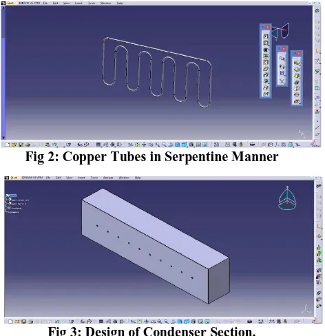
To design the pulsating heat pipe CATIA software is used. This CAD software helps to crate 2D and 3D solid models without any complexity, quickly in an effective manner. The main advantage of CATIA is user friendly, simple graphics user interface, easy to use compared to any other CAD software’s. It contains mechanical design, analysis and simulation, digital mock-up etc. In the present work Copper is selected as material for tubes. PHP consists of 5 turn copper tubes has been designed to fill the working fluid after evacuation is processed.
Fig 2: Copper Tubes in Serpentine Manner
2234 Fig4: Design of Evaporator Section
Fig 5: Assembly of PHP 3 .FABRICATION OF PHP
The tube is wound in serpentine manner to make five turns. The tube has inner and outer diameters of 4 and 6mm respectively. This is then attached to the evaporator and condenser through suitable manufacturing process. The evaporator and condenser both are made up of mild steel and have dimensions of 600*150*150mm and 600*100*150mm respectively. Heat input is given at the evaporator side through a heater. Two valves are fixed on the condenser side through ‘T’ joints to fill and evacuate the working fluid. A total of ten temperature sensors are placed. Four at the condenser section, three at the adiabatic and three at the evaporator sections respectively. The filling ratio employed is 60% and also a pressure gauge is fixed at the top of the condenser. Vacuum pump is used to evacuate and small syringe is used to fill the fluid.
3.1 Manufacturing Methods Involved
The manufacturing process that was followed for the fabrication of a pulsating heat pipe is described in the following steps
Step 1- The copper pipe was cut into required lengths for various parts of setup.
Step 2- The pipes which will form the evaporator zone and condenser zone were bent using a 50mm die. Step 3- The evaporator and condenser boxes were made out of a mild steel plate of 1mm thickness by using ARC welding.
Step 4- The top plate of the evaporator and bottom plate of the condenser were drilled with 6.5mm holes so as to insert the pipe into respective boxes.
Step 5- The inserted pipes are then brazed to form a continuous closed loop using copper electrode. Step 6- This closed loop pipe is then brazed to the evaporator and condenser boxes by silver electrode as to avoid any water leakages.
Step 7- The heater is fitted in the evaporator box by welding a rod and fixing the heater on that rod. Step 8- The sealed closed loop is evacuated by using the vacuum pump.
Step 9- Thermocouples are connected to the PHP near the condenser, evaporator and adiabatic regions. These are connected to the digital temperature indicator. Step 10: Adiabatic regions are insulated to avoid any heat losses.
For manufacturing of pulsating heat pipe, Pipe bending, drilling, brazing, sheet bending and evacuation techniques are used.
4. EXPERIMENTAL SETUP
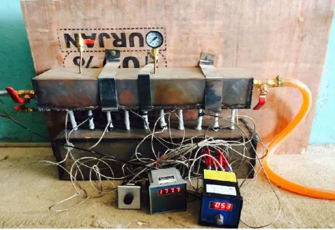
Schematic representation of the fabricated PHP with five turns is shown below. It consists of evaporator, condenser and adiabatic sections, a pressure gauge, temperature indictors, heat input, thermocouples, inlet ad outlet arrangement of water to and from the condenser [10].
Fig 6: Fabricated PHP
4.1 Experimental Procedure
Test run is conducted on the experimental setup .the following procedure is adopted.
Check all the electrical and electronic connections before operating.
Power is supplied to the heater.
All the connections are made to the pipes by thermocouples and wattmeter is checked and power is supplied.
Heat input is supplied through power from 150-250W.
Power is switched on and waits for some time to take the readings.
Reading of wattmeter is noted down.
2235 The readings are noted down for every 3-4 minutes
along with wattmeter readings until there exists no change in temperature values.
The test run is continued till the steady state temperature is reached.
From the readings of evaporator and condenser sections thermal resistance is calculated
Table 2: Properties of the selected Php material
Material used for pipe Copper Thermal conductivity 383 W/m K Density 8954 Kg/m3
Table3: Properties of the working fluid (water)
Working Fluid Water Density of the fluid (
5. RESULTS AND CONCLUSIONS:
The experiment is conducted for different heat input varying from 150 to 240 Watts. The corresponding temperatures are recorded at each section of pulsating heat pipe.
Temperature difference of Evaporator
Tde
= Ta – Tse Temperature difference of Condenser Tsc = Ta – Tsc
Thermal resistance R = (Te –Tc)/Q k/W
Heat Transfer Coefficient h = Q/ (As x
∆
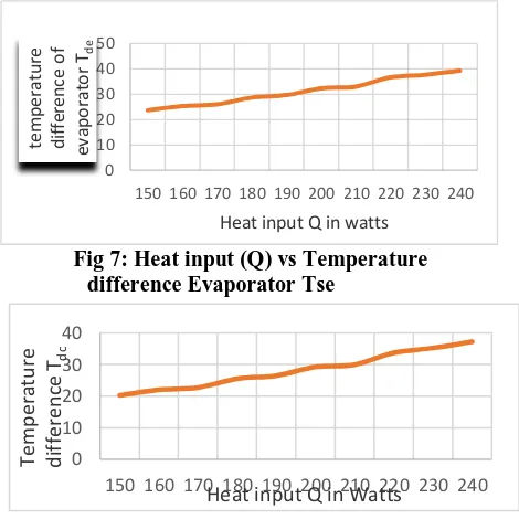
T) W/m2k 5.2 Conclusions:With increasing heat input values the Evaporator temperature increases and also it is concluded that thermal resistance decreases with increasing heat input. The results obtained are represented graphically
Fig 7: Heat input (Q) vs Temperature difference Evaporator Tse
Fig 8: Heat input (Q) vs Temperature
difference Condenser Tsc
From Newton’s law of cooling the difference of evaporator and condenser temperature is varies with heat input value. The above figure shows with increase of Q from 150 to 240 watts the temperature difference also rises.
Fig 9: Heat input (Q) vs Thermal resistance (R)
From the experimental values the above figure shows that thermal resistance decreases as heat input values increases.
Fig 10: Heat input (Q) vs Heat transfer coefficient (h)
150 160 170 180 190 200 210 220 230 240
te
Heat input Q in watts
0 10 20 30 40
150 160 170 180 190 200 210 220 230 240
Tem
Heat input Q in Watts
0
150 160 170 180 190 200 210 220 230 240
Th
Heat input Q in Watts
0
150 160 170 180 190 200 210 220 230 240
H
2236
The convective heat transfer coefficient value is directly proportional to heat input. From the Figure it is concluded that with an increase of heat input value heat transfer coefficient value increases as Q=h*A* ∆T.
REFERENCES
[1] Sameer Khandekar and Manfred Groll, Closed and open loop pulsating heat pipes by at 13th International Heat Pipe Conference (13th IHPC), Shanghai, China.
[2] Mauro Mameli, Marco Marengo, and Stefano Zinna - Thermal Simulation of a Pulsating Heat Pipe: Effects of Different Liquid Properties on a Simple Geometry, Department of Industrial Engineering, University of Bergamo, Dalmine (BG), and Italy 2 Uni heat S.r.l., Bagnatica (BG), and Italy.
[3] Md Shahidul Haque-Thermal characteristics of an aluminum closed-loop pulsating heat pipe charged with ammonia, thesis for masters of engineering.
[4] Sameer Khandekar and Manfred Groll- On the definition of pulsating heat pipes: an overview, 5t Minsk International Seminar, Minsk, Belarus, 2003.
[5] Sameer Khandekar and Manfred Groll- Closed and open loop pulsating heat pipe, 13th
International heat pipe conference, Shanghai, China, September 21-25, 2004.
[6] Akachi, H. and Polášek, F., “Pulsating Heat Pipes”, 5thInt. Heat Pipe Symposium, Melbourne, Australia, 17 - 20 November 1996.
[7] Dobson, R. T. and Graf, G., “Thermal Characterization of an Ammonia-charged Pulsating Heat Pipe”, Proc. 7th IHPS. pp.460-466 , 2003
[8] Khandekar, S. and Groll, M., “Pulsating Heat Pipes: Study on a Two-Phase Loop”, Proc. 13th Int. Conf. on Thermal Engineering and Thermo grammetry (THERMO), 2003. [9] Khandekar S., “Thermo-hydrodynamics of
Closed Loop Pulsating Heat Pipes, “Doctoral dissertation, University Stuttgart, Germany, 2004.