ISSN(Online): 2319-8753
ISSN (Print): 2347-6710
I
nternational
J
ournal of
I
nnovative
R
esearch in
S
cience,
E
ngineering and
T
echnology
(A High Impact Factor, Monthly Peer Reviewed Journal)
Vol. 5, Issue 2, February 2016
Design and Analysis of Polymer PEK Spur
Gear under Static Loading Condition Using
FEA
Amol C Dhomse1, R.K.Agrawal 2
P.G. Student, Department of Mechanical Engineering, YTIET, University of Mumbai, Maharashtra, India1
Professor, Department of Mechanical Engineering, YTCEM, University of Mumbai, Maharashtra, India2
ABSTRACT: This work presents the design and Analysis of polymer PEK spur gear and Comparison of results of PEK with Metallic Cast Iron under limited loading conditions. Application of Plastic gear reduces the weight and noise, vibration. Analytical Method is used to calculate Tooth load with help of Lewis equation &dynamic tooth load with help of Buckingham equation. Gear profile modelling is done by using Solidworks 2015. Finite Element Method is used for Static analysis of the gear to find the Von-misses stress on the tooth of the gear using ANSYS and these values are compared with Analytical values.
KEYWORDS:Gear Profile,Solidworks 2015, Finite element Method, ANSYS.
I. INTRODUCTION
Due to High strength to weight ration and Low noise vibration, High Corrosion resistant and Low maintenance Plastic gear finding their application in every industries. Polymer Ether Ketone is a family of plastic material available. PEK material will be considered as most superior polymer material even over existing PEEK material. It could well lead to more than 70% weight reduction, more than 3 db of noise reduction and more than 80% reduction in moment of inertia when used as gear material over standard metal materials commonly used in gear industry.
PEK has more resistance to high pressure water and steam, higher melting point temperature and glass transition temperatures as against PEEK. Besides, Strength, wear and thermal properties of PEK makes it perfect replacement of PEEK material.
Existing applications of PEEK material, mainly in aerospace, surgical implants, oil and gas filters and gears are all set for usage of PEK as substitute for better results. PEK applications can even be 3-d printed using SLS.
In this papers following two materials are considered and analyzed for loading conditions. 1. PEK
2. Cast iron
PEK: Ultra-high Performance Thermoplastic (Poly Ether Ketone) material, virgin, semi crystalline granules suitable for injection molding, easy flow, Beige in color. Application Areas: Suitable for high temperature application, high wear & abrasion resistance, high chemical resistance & for metal to plastics conversion etc.
Cast Iron: Cast iron is a group of iron-carbonalloys with a carbon content greater than 2%. The alloy constituents affect its color when fractured: white cast iron has carbide impurities which allow cracks to pass straight through. Grey
cast iron has graphite flakes which deflect a passing crack and initiate countless new cracks as the material breaks.
II. GEAR DESIGN
Gears are defined as toothed wheel used for transmitting both motion and power from one shaft to another shaft by successive engagement of teeth.
Gears are mainly classified
ISSN(Online): 2319-8753
ISSN (Print): 2347-6710
I
nternational
J
ournal of
I
nnovative
R
esearch in
S
cience,
E
ngineering and
T
echnology
(A High Impact Factor, Monthly Peer Reviewed Journal)
Vol. 5, Issue 2, February 2016
1. Parallel 2. Intersecting
3. Non-intersecting and non-parallel
B.According to peripheral velocity of gears 1. Low
2. Medium 3. High
C.According to type of gearing 1. External
2. Internal
3. Rack and pinion
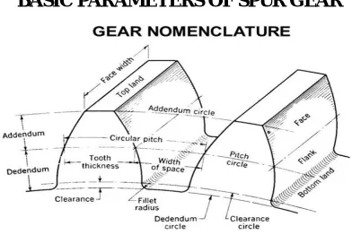
BASIC PARAMETERS OF SPUR GEAR
Fig 1. Gear Nomenclature
Module: It is the ratio of the pitch circle diameter in millimeter to the number of teeth.
Addendum: It is the radial distance of a tooth from the pitch circle to the top of the tooth.
Dedendum: It is the radial distance of a tooth from the pitch circle to the bottom of the tooth.
Tooth Thickness: The thickness of the tooth along the pitch circle is called the tooth thickness.
Face width: It is the width of gear tooth measured parallel to its axis.
Pressure Angle: The angle between the line joining the centers of the two gears and the common tangent to the base circles.
SPUR GEAR TOOTH PROFILE DESIGN
1. Consider a Gear made of 2. Module (m) = 4,
3. Number of Teeth (Z) = 18 4. Pressure Angle (α) =
5. Other Tooth parameters are calculated by Involute teeth standards. 6. Pitch Circle Diameter (D) = module ×Number of Teeth
D = 4×18 7. D = 72mm
8. Circular pitch (C.p) = Pc = πD/T = π×72/18 = 12.568 9. Diameteral pitch (D.P) = T/D = 18/72 = 0.25
10. Addendum = m = 4 mm 11. Dedendum= 1.25m = 5 mm
12. Tooth Thickness = 1.5708m = 6.2832 mm 13. Fillet radius = 0.4m = 1.6mm
ISSN(Online): 2319-8753
ISSN (Print): 2347-6710
I
nternational
J
ournal of
I
nnovative
R
esearch in
S
cience,
E
ngineering and
T
echnology
(A High Impact Factor, Monthly Peer Reviewed Journal)
Vol. 5, Issue 2, February 2016
16. Addendum Circle diameter = 2×Addendum+ Pitch Circle Diameter 17. = 2×4+72
18. = 80 mm
19. Dedendum Circle Diameter = Pitch Circle Diameter-2×Dedendum 20. = 72-2×5
21. = 62 mm
22. Clearance Depth = 0.25×m = 1m
DESIGNING OF SPUR GEAR ASSUMPTION:
1) Effect of radial load( ) which induces compressive stress is neglected.
2) Tangential load ) is uniformly distributed over the entire face width. 3) The effect of stress concentration is neglected.
4) At any time, only one pair of teeth is in contact i.e. contact ratio is 1. 5) The tooth is assumed to be cantilever.
6) Selecting full Depth involutes’ tooth system.
TANGENTIAL TOOTH LOAD CALCULATION:
Considering Gear to transmit power of 10KW rotating with a speed of 500rpm. The following parameters are calculated. Considering factor of safety: FOS=4
Mean velocity is
Velocity factor is
Apply the Lewis equation
Tangential load is calculated as follows
Bending strength is
= 27.5 * 1.627 = 44.74 MPa
SR
NO PARAMETERS
YEILD STRENGTH
BENDING STRENGTH
TANGENTIAL TOOTH LOAD
1. PEK 110 44.74 2323.75
ISSN(Online): 2319-8753
ISSN (Print): 2347-6710
I
nternational
J
ournal of
I
nnovative
R
esearch in
S
cience,
E
ngineering and
T
echnology
(A High Impact Factor, Monthly Peer Reviewed Journal)
Vol. 5, Issue 2, February 2016
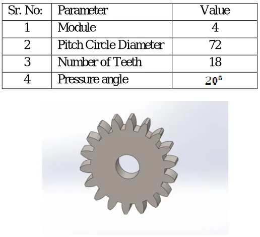
MODELLINGOFSPURGEAR
Spur gear is modelled in Solidworks 2015 using Parametric Design, so that it can be easily editable as per customer requirement means Customization becomes very easy. Parameters required for parametric designing is as shown below in table. Fig b Modelling of Spur Gear in SOLIDWORKS 2015
Sr. No:
Parameter
Value
1
Module
4
2
Pitch Circle Diameter
72
3
Number of Teeth
18
4
Pressure angle
Fig 2. Modelling of Spur Gear in SOLIDWORKS 2015
III. EXPERIMENTAL RESULTS
Finite element analysis of Spur gear is analyzed using ANSYS 14.0. By FEM we calculated the Bending stress produced in the spur gear when it is considered as a cantilever beam subjected to transverse tangential load. Simulation results of spur gear are shown below. Figs. 2 (a) Boundary condition of PEK (b) Different fixed support and forces (c) Meshing of PEK Spur Gear
I.
ISSN(Online): 2319-8753
ISSN (Print): 2347-6710
I
nternational
J
ournal of
I
nnovative
R
esearch in
S
cience,
E
ngineering and
T
echnology
(A High Impact Factor, Monthly Peer Reviewed Journal)
Vol. 5, Issue 2, February 2016
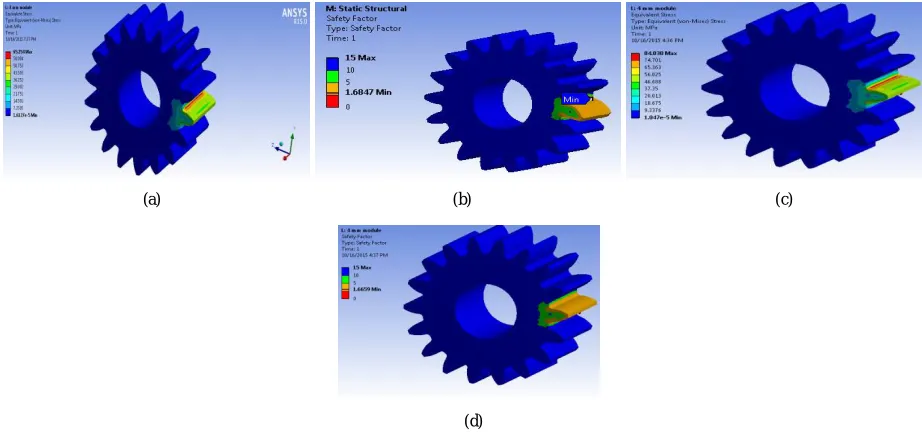
Fig. 4 (a) Von Mises Stress distribution in PEK spur Gear (b) Factor of Safety of PEK (c) Von Mises Stress distribution in Cast Iron spur Gear (d) Factor of Safety of Cast Iron
Finite Element Method results shows that bending stress produced in PEK gear is less as compared to Cast iron Gears. These values are calibrated by analytical method to find the bending stress.
RESULTS
Materials
Von misses Stress, MPa
Analytical Stress FEA Stress
PEK 44.74 65.254
Cast Iron 56.94 84.038
IV. CONCLUSION
Analytical and Finite Element Methods are applied to check the Bending stress produced in the spur gear. The results show that spur gear made from PEK has more bending strength than Cast Iron Spur gear. Also the Density of PEK is also less than the cast iron. So by replacing cast iron Gear by PEK gear we can achieve high strength, Low Weight and Noise free Motion of Gears.
REFERENCES
[1] Pravin Kumar, Harsh Raghuvanshi, “DESIGN AND ANALYSIS OF SPUR GEAR DIFFERENT GEOMETRIC CONDITIONS“,International Journal of Engineering & Advanced Technology (IJEAT), ISSN:2249-8958, Volume-3, Issue-2, December 2013
[2] Utkarsh.M.Desai, Prof.Dhaval.A.Patel, “MODELING AND STRESS ANALYSIS OF COMPOSITEMATERIAL FOR SPUR GEAR UNDER STATIC LOADINGCONDITION”, Technical Research Organization India,
(a) (b) (c)
ISSN(Online): 2319-8753
ISSN (Print): 2347-6710
I
nternational
J
ournal of
I
nnovative
R
esearch in
S
cience,
E
ngineering and
T
echnology
(A High Impact Factor, Monthly Peer Reviewed Journal)
Vol. 5, Issue 2, February 2016
[3] V. Siva Prasad, Syed Altaf Hussain, V.Pandurangadu, K.PalaniKumar, “MODELING AND ANALYSIS OF SPUR GEAR FOR SUGARCANE JUICE MACHINE UNDER STATIC LOAD CONDITION BY USING FEA”, International Journal of Modern Engineering Research (IJMER), ISSN: 2249-6645, Volume-2, Issue.4, July-Aug 2012
[4] Pradeep Kumar Singh1, Manwendra Gautam1, Gangasagar1 and Shyam Bihari Lal “STRESS ANALYSIS SPUR GEAR DESIGN BY USINGANSYS WORKBENCH”, International Journal of Mechanical Engineering and Robotics Research, ISSN 2278 – 0149, Vol. 3, No. 3, July 2014
[5] A. Thirugnanam, J. Sathish and Lenin Rakesh , “CONTACT ANALYSIS OF SPUR GEAR USING COMPOSITE MATERIAL(NYLO CAST)”, Middle-East Journal of Scientific Research 20 (3), ISSN 1990-9233,2014
[6] Mahebub Vohra, Prof. Kevin Vyas, “comparative FINITE ELEMENT ANALYSIS OF METALLIC AND NON-METALLIC SPUR GEAR”, IOSR Journal of Mechanical and Civil Engineering (IOSR-JMCE) e-ISSN: 2278-1684,p-ISSN: 2320-334X, Volume 11, Issue 3 Ver. IV (May- Jun. 2014)
[7] Amarjeet R. Gupta, “APPLICATION OF DIFFERENT THERMOPLASTIC GEARS IN THE GEARBOX OF MOPED”, International Journal for Engineering Applications and Technology (IJFEAT), ISSN: 2321-8134, Issue: 2(1):10Oct,2013
[8] Sandeep C. Dhaduti1, Dr. S. G. Sarganachari,“REVIEW OF COMPOSITE ASYMMETRIC SPUR GEAR”,International Journal of Engineering Research, ISSN:2319-6890,Volume No.4, Issue No.2,01 Feb. 2015
[9] A. K. Wood, V. Williams and R. Weidig, “THE RELATIVE PERFORMANCE OFSPUR GEARS MANUFACTURED FROM STEEL AND PEEK”, (Reprinted with kind permission of the VDI International Conference on Gears, Technical University of Munich 2010), March/April 2012
[10] Dr.Ir H.G.H.van Melick, “TOOTH-BENDING EFFECTS IN PLASTIC SPUR GEARS”, www.geartechnology.com, September/October 2007 [11] S. Senthilvelan and R. Gnanamoorthy,“CONDITION MONITORINGOF NYLON AND GLASS FILLED NYLON GEARS