589 | P a g e
IMAGE ENHANCEMENT USING MATLAB
Kirti Agrahari
1, Diksha Srivastava
2, Purnima Tripathi
31,2,3
Department of Electronic and Communication,
Engineering Buddha Institute of Technology Gida Gorakhpur (India)
ABSTRACT
With rapid growth of human-computer interaction, more and more useful software are replacing human efforts. This paper integrates the idea to process an image for reduction of image size and enhancement of image as per our application. Reduction in salt and pepper noise is also proposed in the present work. Quality of the image is not satisfactory in many cases to find out the meaningful information. As all enhancement techniques are application oriented, it is necessary to find a method which needs simple operations with effective enhancement and does not require complex operations like logarithmic, exponential, Probability Density Function. We can remove noise from image, detect the edge of image, convert the rgb image into binary etc. The noise destroys the original image quality by changing the true pixel value. So for reduction of noise from an original image it is very much essential to distinguish the type of noise, its effect in an image and its reduction technique. The proposed method provides good results subjectively as well as objectively for both gray scale and true colour images. The proposed method is useful for interactive image processing applications as it has a family of possible transformations for various enhancement levels.
Keywords: Image enhancement (IE), Digital image processing (DIP), Probability density function
(PDF).
I. INTRODUCTION
The image enhancement is a technique or in other words process of adjusting the digital images and the resultant
image which we get are more suitable for display. The aim of image enhancement is to improve the perception of
information in image for human viewers and also for other automated image processing technique. It is a method to
perform an operation on an image , in order to get an enhanced image and extract some information to it. In this
image processing, the input is an image and output may be the special characteristics associated with that particular
image. For this purpose MATLAB is a very powerful tool. MATLAB is developed by Math works and it is a high
performance language to do programming in easy-to-use environment. The main advantage of MATLAB is its
numerical precision is very high. different technique will applied pixel to pixel to perform so many task- like
converting a image into Black and white., binary image, negative of an image, increasing its brightness, edge
detection, removing salt and pepper noise etc. An image is supposed to provide information to the human viewers.
590 | P a g e
score over computers in recognition capability. Human beings use all the five sensory organs to gather informationabout the outside world. The old Chinese proverb „A picture speaks a thousand words‟ rightly points out that the
images are very powerful tools to provide information to the viewers in every field i.e., medical images for doctors,
forensic images for police investigation, text images for readers etc. In the process of image acquisition, image
clarity is affected by lighting, weather, distance, or equipment used for image capture. Enhancement basically
improves visual quality by providing clear images for human observer and/or for machine in automatic processing
techniques.
The system we propose in this paper integrates the idea to process an image for reduction of image size and
enhancement of image as per our application. The proposed work describes the method of accessing every picture
element of an image using Matlab. Different Enhancement techniques will be applied pixel to pixel to perform
various tasks.
And they are described below –
1.1.
Black & white image:
A black and white image means that the image has the maximum range up to 2n, starting from 0 to 2n (where n is
number of bit / bits in one pixel).This is also called a gray scale image. Black and white image has pure black means
0 up to pure white means 2n. for example- if one pixel have 8 bits than the values are in between 0 (pure black) to
255 (pure white).The BW (Black and White) image and Binary image both are different with each other as we can
see in the following images.
1.2.
Binary image :
A binary image is a digital image that has only two possible values of each pixel. Typically, the two colours used for
binary image are black and white, though any two colours can be used. The colour used for the object(s) in the
image is foreground colour while the rest of the image is the background colour. Binary images are also called
bi-level or two-bi-level. This means that each pixel is stored as a single bit i.e., 0 (black) or 1 (white).
1.3.
Negative of an image:
Negative of an image is also called complement of that image. In the complement of binary images zeros becomes
ones and ones become zeros; black and white are reversed. The complement of an intensity or RGB image, each
pixel value is subtracted from the maximum pixel value supported by the class (or 1.0 for double precision images)
and the difference is used as the pixel value in the output image. In the output image dark areas are become lighter
and light areas are become darker.
1.4.
Brightness of an image:
Customized brightness of an image means to enhance the brightness of the image so that it looks clear and
attractive. In customized brightness of an image we can change the image contrast and brightness of the image.
1.5.
Edge detection:
Edge detection is a technique for finding the boundaries of objects within images. It works by detecting
591 | P a g e
image processing, computer vision and machine vision. In an image, an edge is a curve that follows a path of rapidchange in image intensity.
1.6.
Removing salt and pepper noise of an image:
Salt and paper noise is form of noise sometimes seen on images. It presents itself as sparsely occurring white and
black pixels. An effective noise reduction method for this type of noise is a median filter or a morphological filter.
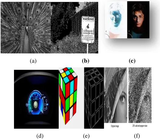
(a) (b) (c)
(d) (e) (f)
Fig 1: (a)A Black & White image, (b) A binary image, (c)Negative of an image, (d)A customized brightness in an
image, (e)Edge detection of an image, (f)Removal of Salt and pepper noise of an image.
III
.
INDENTATIONS AND EQUATIONS
Some equations that are used in the programming are given below-
1. For loading image :
global im im2
[Path]=imgetfile();
2. For binary image :
global im
a=im2bw(im);
3. For gray image :
global im
imgray=(im(:,:,1)+im(:,:,2)+im(:,:,2));
4. For sliders:
592 | P a g e
val=2*get(hObject,‟value‟);ibt=im2+val;
b). global im
val=get(hobject,‟value‟);
c==(im(:,:,1)+im(:,:,2)+im(:,:,2))/val;
IV. FIGURES AND TABLES
The enhanced result show that after converting the images, we meet up with certain advantages, like converting
RGB image to binary image, black and white and negative of an image ,the output image which we get will visible
to us with their contrast values. One can decide its own value and can get special effects in an image. Moreover,
brightness of an image, edge detection and removing salt and pepper noise will help to increase the effectiveness of
an image in terms of clearing the image without any noise because noise are in form of small black and white dots
present on an image making it unclear. It is also use for data hiding techniques.
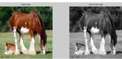
Black & White image
Fig. 2.1: Black and White image
Discussion
There is reduction in memory size after converting in image, the reduction in memory size can be seen in the above
diagram. It helps in data saving. In gray scale images whole object is visible to us with their contrast values in black
and white (0 -255 for 8 bit size of one pixel)
Binary image:
593 | P a g e
DiscussionThere is reduction in memory size after converting in image, the reduction in memory size can be seen in the above
diagram.It helps in data saving. For example - If in a traffic system we want to note the numbers of vehicles then
there is no means of the colours and designs of the number plate of vehicles before recognizing it in the camera, first
we convert it in binary so that it can detect the number and then start our further process. We can decide our own
offset value according to us.
Negative of an image
Fig. 2.3: Negative of an image
Discussion
There is reduction in memory size after making negative of an image ., the reduction in memory size can be seen in
the above diagram .We use negative effect in focusing the primary objects more than secondary objects. This is
called special effects and these are also used in DSLR cameras these days most. It slightly blurs the secondary
objects than primary that are also seen these days in wedding images, and movies etc. Negative of any image is just
complement of the original image means the pixel values get subtracted from the maximum value.
Edge Detection
594 | P a g e
Fig. 2.5: Different type of edge detection imagesDiscussion
There is reduction in memory size in finding the edges of any image, this memory sizes can be seen in the above
diagram. It helps us to recognize those images which are not visible clearly. This can be determining after finding
the edges of that particular image. Edge detection is one of the initial steps to detect vehicles on road for analyzing
behaviour of the vehicles. Edge detectors are also used in face recognition, x – rays etc.
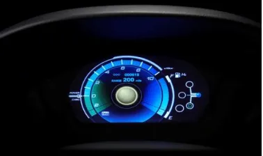
Brightness of an image
Fig. 2.6 Bright image with its original image
Discussion
There is no reduction in memory size in increasing brightness of the image; this memory size can be seen in the
above diagram. It helps us to see those images which are not visible clearly. Customized brightness are used in
LCDs, LEDs and mobile phone display etc
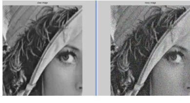
Removal of salt and pepper noise
Fig. 2.7: Salt and pepper noise with its clear image
Discussion
If unwanted information comes on your image in the form of dots (basically black & white), they are not
595 | P a g e
removing salt and pepper noise from any image, this memory size can be seen in the above diagram. It helps us tosee those images which are not visible clearly .Salt and pepper noise images are also used for data hiding.
Tabular & Graphical representation of above results is as follows –Table
Fig. 3.1: Tabular representation of memory sizes
Fig. 3.2: Graphical representation of different memory sizes of input and output image sizes with their reduced
memory size
V. CONCLUSION
This technique gives us freedom to decide own offset value according to user that means it provide flexibility to a
user. The resultant image will change according to the offset value. For further advancement of this signal
processing technique we can make a GUI(Graphical user interface) in which the image will convert as per the user
596 | P a g e
Fig. 4.1: An image of a GUIThe following conclusions are
-From above we conclude that all the tasks that we perform in this project are gives us freedom to decide the offset
value at which we want to enhance the image. There is reduction in memory size of the image in every enhancement
process. There is only need of information from any image so we have applied the above tasks on an image to
reduce memory. Here end user can access according to him / her... If we buy software for different enhancements
techniques then there is fixed offset level so if we want to enhance the image at our offset value then we can‟t do
.After performing these tasks according to us we can save data also according to us more and more and this will
depend on offset value that we decide. We use negative effect in focusing the primary objects more than secondary
objects. This is called special effects and these are also used in DSLR cameras these days most. It slightly blurs the
secondary objects than primary that are also seen these days in wedding images, and movies etc. By deciding the
offset value the appearance of primary objects is clearer.
VI. ACKNOWLEDGEMENTS
I take this opportunity to express my profound gratitude and deep regard to my guide Mr. Amit Kumar for his
exemplary guidance, monitoring and constant encouragement throughout the course of this project. The blessing,
help and guidance given by his time to time shall carry me a long way in the journey of life on which I am about to
embark.
I am obliged to staff members of ECE Department, for the valuable information provided by them in their
respective fields. I am grateful for their cooperation during the period of my assignment. Lastly, I thank almighty,
my parents, brother, sister and friends for their constant encouragement without which this assignment would not be
possible.
VII. FUTURE SCOPE
Continuously increment in computing power of implementation platforms, executed under real time constraints.
Real time application may consist of different image standards, or different algorithms used at different stages of the
597 | P a g e
between flexibility and performance. We can prepare a Graphical User Interface (GUI). In which we can applyoffset value directly by push buttons on our GUI and will get the respective results instantly with their respective
Histograms.
REFERENCES
[1] Ms. I. Suneetha and Dr. T. Venkateswarlu. 2012. Enhancement Techniques for Gray scale Images in Spatial
Domain. International Journal of Emerging Technology and Advanced Engineering, website: www.ijetae.com
(ISSN 2250-2459). 2(4): 13-20.
[2] Ms. I. Suneetha and Dr. T. Venkateswarlu. 2012. Enhancement Techniques for True Colour Images in Spatial
Domain. International Journal of Computer Science and Technology (IJCST). Website: www.ijcst.com (ISSN
0976-8491). 3(2), April to June.
[3] R C Gonzalez and R. E. Woods. 2008. Digital Image Processing. 3rd Edition, Prentice Hall.
[4] J. Y. im, L. S. Kim and S. H Hwang. 2001. An advanced Contrast Enhancement Using Partially Overlapped
Sub-Block Histogram Equalization. IEEE Transactions on Circuits and Systems for Video Technology. 11(4):
475-484.
[5] Kh. Manglem Singh, Romen Singh, Rupachandra Singh and O. Imocha Singh. 2010. Image Enhancement by
Adapted Power Law Transformation. BUJICT, September.
[6] J.S. Lee. 1980. Digital image enhancement and noise filtering by use of local statistics. IEEE Trans. On Pattern
Analysis and Machine Intelligence, PAMI-2: 165.
[7] Abdel-Ouahab BOUDRAA and EI-Hadji Samba DIOP. 2008. Image Contrast Enhancement Based on 2D
Teager-Kraiser Operator. ICIP, IEEE 978-1-4244-1764.
[8] R. C. Gonzalez and R. E. Woods, Digital Image Processing, 2nd ed. Prentice-Hall India, 2005.
[9] A. K. Jain, “Fundamentals of Digital Image Processing”, Prentice Hall of India, First Edition, 1989.
[10] ” Digital Image Processing” S Jayaraman, S EsaKkirajan, T VeeraKumar, Tata McGraw Hill,2009
[11] P. Kamboj, “A brief study of various noise models and filtering technique”, Journal of Global Research in
Computer Science ,Volume 4, No. 4, April 2013
[12] A novel approach to noise reduction for impulse noise and Gaussian noise” P. Krishnapriya, Mr. S. Sanjeev
Kumar, IJETAE, International Conference on Information Systems and Computing, vol.-3, January 2013
[13] R. H. Chan, Chung-WaHo, M. Nikolova, “Salt and Pepper Noise Removal by Median Type Noise Detectors
and Detail –Preserving Regularization,” IEEE Transactions on Image Processing, Vol. 14, No.10, pp. 1479-
1485, October 2005
[14] Alessandro Foi, MejdiTrimeche, Vladimir Katkovnik, and Karen Egiazarian.Practical Poissonian-Gaussian
noise modeling and fitting for singleimage raw-data. IEEE Transactions on Image Processing, 17(10):1737–
1754, 2008.
[15] Kamboj P. & Rani V., (2013) “A Brief study of various noise models and filtering techniques,”Journal of
598 | P a g e
[16] Dainty, J.C. 1971. Detection of images immersed in speckle noise. OpticaActa, Vol. 18, No. 5, pp.327-339.[17] T. Chhabra, G. Dua and T. Malhotra (2013) “Comparative Analysis of Denoising Methods in CT Images”
International Journal of Emerging Trends in Electrical and Electronics, Vol. 3, Issue 2.
[18] Behrens R. T. (1990) “Subspace signal processing in structured noise,” Thesis, Faculty of the Graduate School
of the University of Colorado, the degree of Doctor of Philosophy, Department of Electrical and Computer
Engineering.
[19] Dougherty G. (2010) “Digital Image Processing for Medical Applications,” second ed., Cambridge University
press.
[20] Bhattacharya J. K., Chakraborty D., &Samanta H. S., (2005) “Brownian Motion - Past and Present,” Cornall
university library.arXiv:cond-mat/0511389
[21] Radenovic A., “Brownian motion and single particle tracking,” Advanced Bioengineering methods laboratory,