53 | P a g e
DESIGN AND DEVELOPMENT OF
MULTI-FUNCTION OPERATING MACHINE TOOL
Vikrant R.Kaveri
1, Dr. D.S More
212
Department of Mechanical Engineering, Dr.D. Y. Patil School of engineering, Charholi(Bk), Pune,
Savitribai Phule Pune University.
ABSTRACT
This paper presents the “DESIGN AND DEVELOPMENT OF MULTI-FUNCTION OPERATING MACHINE TOOL” which is mainly carried out for heavy production based industries. So in this paper we have a proposed a machine tool which can perform operations like drilling, grinding, cutting, punching etc. The mentionedoperations can however be replaced by similar type of operations. Industries are basically meant for Production of useful goods and services at low production time, low production cost, machinery cost and low inventory cost. In today’s era every task have been made rapid and faster due to technology enhancement but this advancement also requires huge investments and expenditure ,every industry wills to make high productivity rate maintaining the quality and standard of the product at minimum average cost. We have developed a model of a machine tool which would be capable of performing different operation simultaneously, and it should be economically efficient. Our Objective behind development of this model is to have conservation of electricity (power supply), reduction in cost associated with power usage, increase in productivity, reduced floor space, reduce production time, reduction of human resources etc.
Keywords: Multi-function machine, Drilling machine, grinding tool, Hack-saw blade, punch tool.
1.
INTRODUCTION
This deal with “DESIGN AND DEVELOPMENT OF MULTI-FUNCTION OPERATING MACHINE TOOL”. In today’s era every task have been made rapid and fasterdue to technology enhancement but this
advancement also demands huge investments and expenditure,every industry desires to make high productivity
rate maintaining the quality and standard of the product at low average cost.So in this mechanism we have a
proposed a machine which can perform operations like drilling, grinding, cutting, punching and some other
lathe operations at different working centres simultaneously which implies that industrialist have not to pay for
machine performing above tasks individually for operating operation simultaneously. In present condition many
electrically operated power machines of different companies with different specifications are available for the
54 | P a g e
different materials but they have one and major disadvantage that those are able to perform single operation ofmachining at a time. For industries to achieve the mass production, it is necessary to perform multipleoperations
with high rate. So it is impossible to depend upon conventional single machines and need the improvement in
technology and design of such machines.
Multi-function operation machinetoolhelps us to get high speed cutting rate and to achieve mass production
for maximum profit in related companies. As this machine overcomes all the limitations and drawbacks of
conventional machines, it is also helpful for small scale industries due to its simple working and operating
conditions along with its compatibility, efficiency and affordable price. Moreover, the above mentioned
operations can be replaced by similar type of operations.This machine is may be used in industries and domestic
operation and low production cost. This project work subject is one in which actually we are learning theoretical
concepts in practical view. In an industry a considerable portion of investment is being made for machinery
installation.
AIM AND OBJECTIVE OF WORK
The aim of our project is the” Design and development of MULTI-FUNCTION OPERATING
MACHINE TOOL”, a structure, which is used for performing Simultaneous operations like,
1. Drilling
2. Cutting
3. Grinding
4. Punching
PROBLEM STATEMENT
1. Present machines are very costly and time consuming.
2. Conventional machines require large floor space.
3. Traditional machines are operated by means of electricity which has limited use in the rural areas.
4. Conventional machines are not multi-functional.
2.
LITERATURE REVIEW
Before initiating our research work we have undergone through many research papers which indicates
that for a production based industries machine installation is a tricky task as many factor being associated
55 | P a g e
per machine i.e. capacity ofmachine, time consumption and many more. Some research papers which haveled us to approach to the idea of a machine which may give solution to all these factors are as follows:
Machine tools nowadays have to be veritable “jack of all trades”, able to handle all kinds of materials, to
manage without any process materials as far as possible, and be capable of adapting to new job profiles
with maximized flexibility. Two highly respected experts on machining and forming from Dortmund and
Chemnitz report on what’s in store for machine tool manufacturers and users.
2.1 Heinrich Arnold1 November 2001 rather long re-investment cycles of about 15 years have created
the notion that innovation in the machine tool industry happens incrementally. But looking at its recent
history, the integration of digital controls technology and computers into machine tools has hit the industry
in three waves of technology shocks. Most companies underestimated the impact of this new technology.
This article gives an overview of the history of the machine tool industry since numerical controls were
invented and introduced and analyses the disruptive character of this new technology on the market. About
100 interviews were conducted with decision-makers and industry experts who witnessed the development
of the industry over the last forty years. The study establishes a connection between radical technological
change, industry structure, and competitive environment. It reveals a number of important occurrences and
interrelations that have so far gone unnoticed.
2.2 Dr. Toshimichi Moriwaki (2006) recent trends in the machine tool technologies are surveyed from
the viewpoints of high speed and high performance machine tools, combined multifunctional machine tools,
ultra precision machine tools and advanced and intelligent control technologies.
2.3 Frankfurt-am Main, 10 January 2011 the crisis is over, but selling machinery remains a tough
business. Machine tools nowadays have to be veritable “jack of all trades”, able to handle all kinds of
materials, to manage without any process materials as far as possible, and be capable of adapting to new job
profiles with maximized flexibility. Two highly respected experts on machining and forming from
Dortmund and Chemnitz report on what’s in store for machine tool manufacturers and users. Multi-purpose
machines are the declarations of independence. The trend towards the kind of multi- purpose machining
centres that are able to cost efficiently handle a broad portfolio of products with small batch sizes
accelerated significantly during the crisis. “With a multi-purpose machine, you’re less dependent on
particular products and sectors”, explains Bergmann.
2.4 R.S.Khurmi, J.K.Gupta in their book “Theory of machines” (Velocities in mechanisms) helps to
56 | P a g e
2.5Prof. Nitinchandra R. Patel, Ravi Thakkar, Miteshkumar Rathwa in his research paper “Materialselection and testing of hacksaw blade based on mechanical properties” stated that the appropriate saw
blade must be selected for better operation and fine cutting by selecting number of teeth per inch.
3.
PROPOSED METHODOLOGY
In this project we will generally give the power supply to the shaft on which a pulley is mounted on it,
and a second pulley on parallel another shaft to it has been mounted on a drill shaft to which a drill bit is
being attached. At one end of the shaft is connected to power supply other end is being joined to a circular
disc, through this circular disc scotch yoke mechanism is being performed (rotator y motion is converted to
reciprocating motion) .A shaft consist of grinding wheel at the end.
Fig.1 Proposed methodology
4.
WORKING PRINCIPLE
There are only two majorprinciples on which our proposed machine tool generally works
:
4.1. Scotch-Yoke mechanism
:
The Scotch yoke is a mechanism for converting the linear motion of aslider into rotational motion or vice-versa. The piston or other reciprocating part is directly coupled to a
sliding yoke with a slot that engages a pin on the rotating part. The shape of the motion of the piston is a
57 | P a g e
Fig. 1Scotch-Yoke mechanism4.2. Power transmission through belt& pulley:
4.2.1Working of the Model:
In the conceptual model of “Multi-Functional operating machine tool” we are giving supply to
the main shaft through pulley and belt arrangement as we move along the axis of shaft we have
mounted a scotch yoke mechanism, through the rotary motion of shaft get converted into
reciprocating motion. As we can see that the scotch yoke mechanism is directly fabricated to the
main shaft and has same angular velocity as that of main-shaft shaft. We are giving drive to drill
shaft through belt-pulley arrangement, now again as we move along the next axis of second shaft
further we have again used the bevel gear arrangement to give the drive to grinding centre.
5.
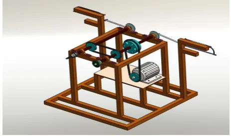
SCHEMATIC DIAGRAM(CAD-MODEL)
Fig. 1 Schematic diagram
6.
SPECIFICATIONS
6.1. Base = L x B = 61x61cm2
6.2. Height = 60cm
58 | P a g e
6.4.Motor speed = 2500 rpm6.5.Grinder wheel dia. = 8.5cm
6.6.Length of main shaft = 42cm
6.7.Dia. of main shaft = 1cm
6.8.Pulley diameter, d 1 = d 2 = d 3 = d 4 = 4.5cm & d 5 = 5.5cm
6.9.L 1 = 45.5cm
6.10. L 2 = 52cm
6.11. Drilling centre pulley dia. = 4cm
6.12. Connecting link hack saw length = 30 cm
6.13. Clamp = 17cm x 17cm
6.14. Dimension of shell = 16cm x 14cm
6.15. Distance between pulleys,
6.15.1. P 1 and P 5 = 17.5cm
6.15.2. P 1 and P 3 = 3cm
6.15.3. P 4 and P 5 = 2.5cm
7. RESULTS
For designing the structure, motor is kept as a main power source. According to our design all the
necessaryparts are assembled. Although we have designed the structure with considering the necessary safety
factors. These are theoretical values that we have collected from the parts from our design dimension. After the
actualmarket research for the availability of the parts of our machine, we are able to process the parts of our
desireddimensions. In that case, the standard parts with an approx. conformance with our calculated values
would bepreferred and corresponding modifications can be done.
8. CONCLUSION
The researchis carried out by us made an impressing task in the field of industrial and automated workshops. It
is very usefully for the workers to work in the industrial workshop are in the service station. This project
research has also reduced the cost involved in the concern. Project has been designed to perform the entire
requirement task which has also been provided.
9. ACKNOWLEDGEMENT
I take this opportunity to thanks Prof. Dr. D. S. More for valuable guidance and for providing all the necessary
59 | P a g e
REFERENCES
10.1 D.V.Sabarinanda, V.Siddhartha, B. Sushil Krishnana, T.Mohanraj, “Design and Fabrication of
Automated Hacksaw Machine”, International Journal of Innovative Research in Science, Engineering
and Technology, ISSN (Online): 2319-8753, volume 3, April 2014.
10.2 Prof. Nitinchandra R. Patel, Mohammad A. Vasanwala, Balkrushna B. Jani, Ravi Thakkar, Miteshkumar
D. Rathwa, ”Material selection and May - 16 ISSN: 2321-8134 http://www.ijfeat.org (C) International
Journal For Engineering Applications and Technology [06-09] testing of hacksaw blade based on
mechanical properties”, International Journal of Innovative Research in Science, Engineering and
Technology,ISSN: 2319-8753, volume 2, Issue 6, June 2013.
10.3 O.Cakir, A. Yardimen, T. Ozben, “Selection of cutting fluids in machining processes”, Journal of
Achievements in Materials and Manufacturing Engineering, volume 25, Issue 2, December 2007.
10.4 R. Subhash, C.M. Meenakshi, K. SamuelJayakaran, C. Venkateswaran, R.Sasidharan, “Fabrication
pedal poweredhacksaw using dual chain drive”,International Journal of Engineering andTechnology,
ISSN: 220-223, volume 3,Issue 2,2014. [5] Dr. V.P. Singh, (2007)”MechanicalVibration”,
10.5 Walter E. Burton, (1964), “Homemade Power hacksaw for less than $20”, Popularscience, Feb 1964.
[10] Micro, Small and Medium Enterprises Development Institute, ”Project profile onhacksaw blade