ISSN(Online): 2320-9801
ISSN (Print): 2320-9798
International Journal of Innovative Research in Computer
and Communication Engineering
(An ISO 3297: 2007 Certified Organization)
Vol. 3, Issue 7, July 2015
Comparative Analysis of MVDR & RLS
Beamforming Algorithm for Smart Antenna
Gunjan N. Jagtap, P. M. Mainkar, Dr. G. N. Muley
Student, ME (Digital System), Dept. of E&TC, MIT, Pune, India
Professor, Dept. of E&TC, MIT, Pune, India
Professor & HOD, Dept. of E&TC, MIT, Pune, India
ABSTRACT: Smart antenna attempt to enhance the received signal, suppress all interfering signals, and increase
capacity. Beamforming is one of the mostly used antenna technique. It adjust the radiation beam in one specific direction also reduces multiple access interference. It also reduces common channel interference and multiple path fading, in result it increases capacity of mobile network. In this paper two antenna beam forming algorithms are compared. These two algorithms are Recursive Least Square (RLS) and Minimum Variance Distortionless Response (MVDR). Outputs of these two algorithms are in weights. By using these outputs weights, two parameters i.e. Mean Square Error and Power Beam Width are calculated and two algorithm are compared by this parameters and respective results are discussed.
KEYWORDS:Recursive Least Square (RLS), Minimum Variance Distortionless Response (MVDR), Mean Square
Error, Power Beam Width;
I. INTRODUCTION
Beamforming algorithms are used in smart antenna array to find spatial signal signature and to calculate beamforming vectors to track the antenna beam on receiver. Smart antenna increases spectrum efficiency, coverage and channel capacity. It uses many other efficient method with the help of which it can track multiple user, which also reduces interference.
Smart antenna are classified into two types, one is switched beam while other is adaptive array system. Switched beam system uses multiple fixed beams to serve the user in desire directions. In this base station switches between several beams and selects the one who provides best performance and accuracy as the mobile user changes its position through cell [3]. To cover a certain area in a specific direction switched beam system uses multiple arrays. In case of phase shifting network multiple beams are used to search for desire signal in specific area and logic controller is used to control the selection of the beam which is governed by an algorithm. Based on the detection of the detector this algorithm decides and select the strongest signal. But this technique is less efficient in high interference region [2] [11].
ISSN(Online): 2320-9801
ISSN (Print): 2320-9798
International Journal of Innovative Research in Computer
and Communication Engineering
(An ISO 3297: 2007 Certified Organization)
Vol. 3, Issue 7, July 2015
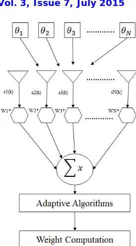
Fig. 1 Block diagram of adaptive beamforming
In adaptive array system strong signals which are capable of dynamically vary the radiation pattern are used by antenna arrays in accordance with the varying environment of the signal. It gives the user maximum radiation in desired direction and also nullify interference.[1].
Blind and non-blind are two types of adaptive algorithms. In non-blind algorithms pilot signal is required to detect the desired signal, which also updates the complex weights. Non-blind algorithm are LMS, RLS and MVDR. Blind algorithms are opposite to non-blind algorithms, it doesn’t required pilot signal to find complex weights. Blind algorithms are CMA, Spectral Self-Coherence Restoral (SCORE) and Decision Directed algorithm (DD) [8] [15].
A. Recursive Least Square Algorithm (RLS):
To calculate weight vectors w (k), RLS algorithm uses method of Least Squares.In RLS weight vector is selected to reduce the cost function which includes sum of error squares over a time window. Weights are calculated using following equations;
R-1(0) = δ-1I,
Where δ is small positive constant and I the N * N identity matrix. for each k
{
k(k ) = R-1 (k-1) x(k)
g(k)= k(k)/(λ+xH(k)k(k))
R-1 (K)= [R (k−1)− ( ) ( )
( ) ( )]
ISSN(Online): 2320-9801
ISSN (Print): 2320-9798
International Journal of Innovative Research in Computer
and Communication Engineering
(An ISO 3297: 2007 Certified Organization)
Vol. 3, Issue 7, July 2015
}
Wherex(k) = input data vector, w(k)= weight vector, e(k) = error signal, k= block length
μ = step size.
g(k)=direction vector
λ is forgetting factor or weighting factor. Its value is such that, 0 ≤ λ≤1 which shows that it is a positive
constant. λ =1 indicates infinite memory and also ordinary least square algorithm is restored [5] [6] [10].
B. MVDR:
One of the beamforming algorithm used in smart antenna is MVDR. In MVDR desired signal is determine by using calculated weight vector from interference. More specifically MVDR provides maximum sensitivity in only one direction. MVDR beamformer is also known as Capon beamformer because it minimizes the output power of the beamformer depending upon the response of the array towards the desired signal [12].
For weight vector calculation the MVDR beam former algorithm does not require knowledge of the direction of the interference. It only takes the value of direction of desired signal. MVDR weight vector is given by:
= ( )
( ) ( )
Where R is covariance matrix should be (N,1 ) for receive signal. H is the hermitian matrix and a( ) is the steering vector which is given by;
( ) =
1
( )
( )( −1)
Where d is the space between the elements of the antenna, is the desired angle, and N is the number of elements [7] [13] [14] [16].
Step 1: Calculating Transmission Energy:
The transmission energy (TEnode )of each node relative to its distance with another node is calculated by using
eq.(1)[8].
TEnodeαdn
TEnode = k dn eq. (1)
where k is constant and n is path loss factor which is generally between (2-4) [8].
II. SIMULATION RESULT
ISSN(Online): 2320-9801
ISSN (Print): 2320-9798
International Journal of Innovative Research in Computer
and Communication Engineering
(An ISO 3297: 2007 Certified Organization)
Vol. 3, Issue 7, July 2015
TABLE 1: SIMULATION PARAMETERS
Number of antenna elements(N)
10
Element Spacing(d)
0.5
λ
Noise Variance(σ)
0.001
Total number of data sample(K)
50
Forgetting factor (
α
) for (RLS)
0.9
DOA of desired signal
0
0DOA of interferer signal(I1)
-30
DOA of interferer signal(I
2)
-60
DOA of interferer signal(I3)
45
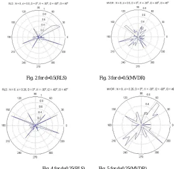
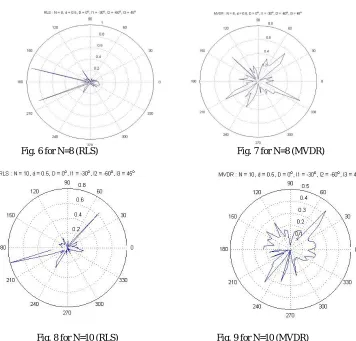
In Figure 2-11, radiation patterns of the two algorithms are shown. Firstly ‘N’ is kept constant at 8 and value of ‘d’ is varied in two values 0.25 and 0.5. Then value of ‘d’ is kept constant at 0.5 and value of ‘N’ varied in three values 8, 10. It can be seen that RLS algorithm is the best choice among the two algorithms because it has least power in the side lobes and has narrowest beamwidth.
Fig. 2 for d=0.5(RLS) Fig. 3 for d=0.5(MVDR)
ISSN(Online): 2320-9801
ISSN (Print): 2320-9798
International Journal of Innovative Research in Computer
and Communication Engineering
(An ISO 3297: 2007 Certified Organization)
Vol. 3, Issue 7, July 2015
Fig. 6 for N=8 (RLS) Fig. 7 for N=8 (MVDR)
Fig. 8 for N=10 (RLS) Fig. 9 for N=10 (MVDR)
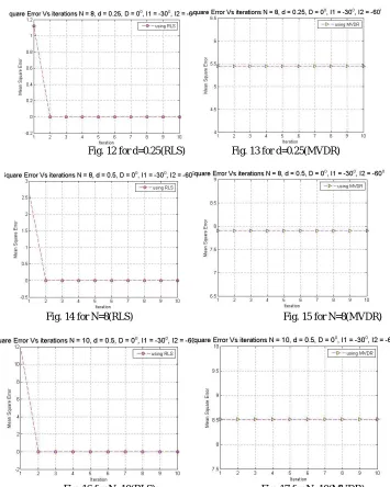
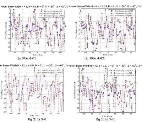
In Figure 12-21, mean square error of the two algorithms are shown. Firstly ‘N’ is kept constant at 8 and value of ‘d’ is varied in two values 0.25 and 0.5. Then value of ‘d’ is kept constant at 0.5 and value of ‘N’ varied in three values 8, 10, and 12. It can be seen that mean square error for MVDR is constant in all the cases, while it became zero in first iteration in case of RLS.
ISSN(Online): 2320-9801
ISSN (Print): 2320-9798
International Journal of Innovative Research in Computer
and Communication Engineering
(An ISO 3297: 2007 Certified Organization)
Vol. 3, Issue 7, July 2015
Fig. 12 for d=0.25(RLS) Fig. 13 for d=0.25(MVDR)
Fig. 14 for N=8(RLS) Fig. 15 for N=8(MVDR)
Fig. 16 for N=10(RLS) Fig. 17 for N=10(MVDR)
ISSN(Online): 2320-9801
ISSN (Print): 2320-9798
International Journal of Innovative Research in Computer
and Communication Engineering
(An ISO 3297: 2007 Certified Organization)
Vol. 3, Issue 7, July 2015
Fig. 18 for d=0.5 Fig. 19 for d=0.25
Fig. 20 for N=8 Fig. 21 for N=10
III.CONCLUSION AND FUTURE WORK
In smart antenna adaptive algorithms are used to control radiation pattern. Adaptive algorithm dynamically optimizes the radiation pattern according to the changing electromagnetic environment. Here we analyse two popular adaptive techniques RLS and MVDR through simulation of various parameters like radiation pattern, mean square error and absolute weights. Comparative analysis of the two algorithms
RLS have narrowest beamwidth, complete rejection of interference and fastest convergence at the cost of high computational burden but has greater power in side lobes. RLS is the best choice where quick tracking of the signal is required. MVDR beamforming requires only desired user direction. It produces the undistorted output with unity gain in desired direction and nulls in direction of interferences. It is not suitable for multipath arrivals as it produces beam only in one desired direction and cancel out signals in other directions.
REFERENCES
[1]Abdul Aziz, M.Ali Qureshi, M. Junaid Iqbal, S.Zeeshan A. Zaidi, “Performance and Quality Analysis of Adaptive Beamforming Algorithms (LMS,CMA, RLS & CGM) for Smart Antennas” 3rd International Conference on Computer and Electrical Engineering “(ICCEE 2010).
ISSN(Online): 2320-9801
ISSN (Print): 2320-9798
International Journal of Innovative Research in Computer
and Communication Engineering
(An ISO 3297: 2007 Certified Organization)
Vol. 3, Issue 7, July 2015
[3] Sheikh.k.; Gesbert D; Gore.D; Paulraj.A “Smart antennas for broadband wirelessacess networks” “IEEEcommunications Magazine” volume 37,issue 11,nov 1999. Page 100-105.
[4] Dahrouj H., Yu W., “Coordinated Beamforming fortheMulticell Multi-Antenna Wireless System”. IEEEtransactions on wireless communications, vol. 9, no. 5,may 2010.
[5] S. Werner, “Reduced complexity adaptive filtering algorithms with applications to communications systems”, Ph.D. dissertation, Helsinki University of Technology, Helsinki, Finland, Oct. 2002.
[6] B. D. Van Veen and K. M. Buckley, “Beamforming: A versatile approach to spatial filtering”, IEEE ASSP Mag., vol. 5, pp. 4–24, Apr. 1988. doi:10.1109/53.665.
[7] ReetaGaokar, Dr. Alice Cheeran, “Performance Analysis of Beamforming Algorithms”, IJECT Vol. 2, Issue 1, March 2011. [8] M. T. Islam, Z. A. Rashid, “MI-NLMS adaptive beamforming algorithm for smart antenna system applications”, July 2006. [9] M. Chryssomallis, “Smart antennas” IEEE antennas and propagation magazine” Vol 42 No 3 pp 129-138, June 2000 [10] S. Rani, P. V. Subbaiah, K. C. Reddy and S. S. Rani,“LMS And RLS Algorithm for Smart Antennas in a W-CDMA Mobile Communication Environment”, ARPN Journal of Engineering and Applied Sciences, VOL. 4, NO. 6, AUGUST 2009.
[11] L.C. Godara,”Smart.Antennas”,CRC.Press.Jan.2004.
[12] Huang Y., Panique M., “Performance analysis of a null steering algorithm”. Proc. IEEE, No. 7, July 2007
[13] P. S. R. Diniz, “Adaptive Filtering: Algorithms and Practical Implementations”, Kluwer Academic Publishers, Boston, 1997.
[14] L. C. Godara, “Applications of antenna arrays to mobile communications, part I:performance improvement, feasibility, and system considerations,” Proceedings of theIEEE, vol. 60, no. 7, pp. 1031–1060, July 1997.
[15] D. Gesbert and P. Duhamel, “Unbiased blind adaptive channel identification,” IEEE Transactions on Signal Processing, vol. 48, no. 1, pp. 148– 158, January 2000.